Home
Search
Collections
Journals
About
Contact us
My IOPscience
Implementation monitoring temperature, humidity and mositure soil based on wireless sensor network for e-agriculture technology
This content has been downloaded from IOPscience. Please scroll down to see the full text. 2016 IOP Conf. Ser.: Mater. Sci. Eng. 128 012044 (http://iopscience.iop.org/1757-899X/128/1/012044) View the table of contents for this issue, or go to the journal homepage for more
Download details: IP Address: 180.214.233.25 This content was downloaded on 27/05/2016 at 15:27
Please note that terms and conditions apply.
International Conference on Innovation in Engineering and Vocational Education IOP Publishing IOP Conf. Series: Materials Science and Engineering 128 (2016) 012044 doi:10.1088/1757-899X/128/1/012044
Implementation monitoring temperature, humidity and mositure soil based on wireless sensor network for e-agriculture technology A Sumarudin*, A L Ghozali, A Hasyim and A Effendi Department of Informatics State Polytechnic of Indramayu, Jalan Lohbener lama no 8 Lohbener Indramayu, west Java, Indonesia *
[email protected] Abstract. Indonesian agriculture has great potensial for development. Agriculture a lot yet based on data collection for soil or plant, data soil can use for analys soil fertility. We propose eagriculture system for monitoring soil. This system can monitoring soil status. Monitoring system based on wireless sensor mote that sensing soil status. Sensor monitoring utilize soil moisture, humidity and temperature. System monitoring design with mote based on microcontroler and xbee connection. Data sensing send to gateway with star topology with one gateway. Gateway utilize with mini personal computer and connect to xbee cordinator mode. On gateway, gateway include apache server for store data based on My-SQL. System web base with YII framework. System done implementation and can show soil status real time. Result the system can connection other mote 40 meters and mote lifetime 7 hours and minimum voltage 7 volt. The system can help famer for monitoring soil and farmer can making decision for treatment soil based on data. It can improve the quality in agricultural production and would decrease the management and farming costs. Keywords: e-agriculture, monitoring soil, sensing, temperature, moisture, humidity.
1. Introduction We propose e-agriculture system for monitoring soil. This system can monitoring soil status. The experimental setup and the preliminary results of the part of the application used for data measurement and data collection as well as initial concepts for improving the monitoring system. The proposed architecture is designed in order to improve the quality in agricultural production and would decrease the management and farming costs. The environmental parameters such as temperature, humidity and moisture should be continually monitored and controlled in order to monitoring plant conditions. Monitoring system based on wireless sensor mote that sensing soil status. This sensor for monitoring utilize soil moisture, humidity and temperature. System monitoring design with mote based on microcontroler and xbee connection. Data sensing send to gateway with star topology with 1 gateway. Gateway utilize with mini personal computer and connect to xbee cordinator mode. On gateway, gateway include apache server for store data based on My-SQL. System web base with YII framework. System done implementation and can show soil status real time. 2. The Design System E-agriculture Content from this work may be used under the terms of the Creative Commons Attribution 3.0 licence. Any further distribution of this work must maintain attribution to the author(s) and the title of the work, journal citation and DOI. Published under licence by IOP Publishing Ltd 1
International Conference on Innovation in Engineering and Vocational Education IOP Publishing IOP Conf. Series: Materials Science and Engineering 128 (2016) 012044 doi:10.1088/1757-899X/128/1/012044
2.1. System Design The design of the system is an overview of the literature that has been studied and then presented to the timetable for implementation in the manufacturing process. In designing this system will be addressed needs that must be met to be able to operate the system in accordance with the plan that is as sender wireless media sensor data using XBee module.
Figure 1. Monitoring System Design 3. The Method Design Implementation For implementation the system, we development with microcontroller for data collection and controller, xbee connection utilize for communication mote end device to gateway system. The step implementation can show on figure 2. In the working system is divided into two design, namely at the time of data transmission and storage of data and view data collection for sensor on web base interface, the figure 3 shows the phases that exist in both the current process is running.
Figure 2. Flowchart of Data Delivery
2
International Conference on Innovation in Engineering and Vocational Education IOP Publishing IOP Conf. Series: Materials Science and Engineering 128 (2016) 012044 doi:10.1088/1757-899X/128/1/012044
Figure 3. Flowchart Displaying Data
Figure 4. Implementation mote
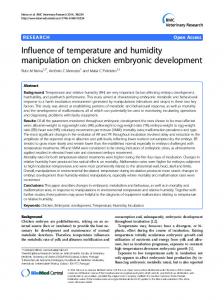
4. Result and Discussion This research produced a way to monitor the temperature and ambient temperature, also on a soil moisture levels. This device can facilitate in monitoring environmental conditions, because it does not have to come directly to check the environmental conditions. This device can also store the data of temperature or ambient temperature also soil moisture during the period desired, and from data stored tersbut be displayed into a website in the form of a line chart and table format with a full day or 24 hours. 3
International Conference on Innovation in Engineering and Vocational Education IOP Publishing IOP Conf. Series: Materials Science and Engineering 128 (2016) 012044 doi:10.1088/1757-899X/128/1/012044
4.1. Working Principle Transmitter Device This monitoring system requires data obtained by the sensors are embedded. The sensors will tersus temperature and humidity transmit data obtained from the surrounding environment and sends it to a server PC wirelessly using a wireless module for 1 hour. This system is capable of running by getting resources from a 7,4V battery with capacity of 1300mAh. 4.2. Working Principle Receiver Devices The data has been sent by the transmitter system will be accepted by the receiver system and then be converted into the form of a data string for the next tersbut will dismpan into a database. 4.3. Test Result Tests carried one by one from the start of testing the communication between the XBee, temperature sensors and temperature (SHT), the humidity sensor (Soil Moisture), and testing to all monitoring tools, testing conducted on the ability of XBee communication and power required to run the transmitter, and the results tests outlined in the table below as follows : Table 1. Table testing distance
No
distance
transmitter system
Receiver System
position
Position
there barrier
Data Sent
1
40m
Outdoor
Indoor
No
Yes
2
40m
Indoor
Indoor
No
Yes
3
40m
Outdoor
Indoor
Yes
No
4
10m
Indoor
Indoor
Yes
Yes
5
10m
Outdoor
Indoor
Yes
Yes
From the table above it can be concluded that the maximum distance to communicate with each other XBee is 40 meters without any obstacle, when the author of more than 40 meters to test the XBee can not communicate. Besides the barrier also interfere with communication between the XBee, XBee only able to communicate at a distance of no more than 10 meters when the two XBee blocked a doorway and surrounded by walls. Table 2. Table testing battery power 7,4v No 1 2 3 4 5 6 7
transmitter system Battery Data Sent Time Yes 7 Volt Yes 6 Volt Yes 5 Volt Yes 4 Volt No 3 Volt No 2 Volt No 1 Volt
4
International Conference on Innovation in Engineering and Vocational Education IOP Publishing IOP Conf. Series: Materials Science and Engineering 128 (2016) 012044 doi:10.1088/1757-899X/128/1/012044
From table 4.3 can be authors conclude that the minimum power needed for XBee able to send the data is equal to 4V. The author tested using li - po battery 1300mAh 7,4V assisted a ubec capable of generating an output of 5V. The result is a system of the sender is able to work for ± 7 hours with the intensity of shipping 1 time for 1 hour, the system stops sending when the remaining battery is less than 4V or approximately 3,24V. Table 3. Testing battery with 12 volt No 1 2 3 4 5 6 7 8 9 10 11 12
transmitter system Battery Time 12 Volt 11 Volt 10 Volt 9 Volt 8 Volt
Data Sent Yes Yes Yes Yes Yes Yes No No No Tidak No No
7 Volt 6 Volt 5 Volt 4 Volt 3 Volt 2 Volt 1 Volt
Table 3 is the result of a second experiment by using li - po battery 12V without using ubec, which at this second trial the sender system is only able to work for ± 4 hours with shipping intensity is the same as the first experiment.
Figure 5. Application image link Figure 2.4 is a picture which time the receiver receives the data, the application will download the user detection receiver port select along boudratenya. After the start button is pressed the data received will be converted into a string and stored into the database.
5
International Conference on Innovation in Engineering and Vocational Education IOP Publishing IOP Conf. Series: Materials Science and Engineering 128 (2016) 012044 doi:10.1088/1757-899X/128/1/012044
Figure 6. Display chart at website monitoring In the Figure 7 displays the results of the data stored into the database in the form of a chart with a 24 -hour format, each data will be retrieved and displayed every hour.
Figure 7. Display data in tabular form In the figure 8 displays data in tabular form. Such as charts, tables display data in 24- hour format in the capture then displayed every hour. 5. Conclusion Based on the above results obtained some conclusions from the manufacture of temperature monitoring system: 1. From the testing that has been done, it can be concluded that the design and implementation of monitoring temperature using the ambient temperature and XBee arduino media has been successful in terms of the accuracy of the sensor with the actual conditions, both when displaying the temperature and the temperature as well as at the time of data transmission. 2. The device temperature and ambient temperature monitoring is enabled and used to the environment temperature and the temperature must be monitored in real-time such as smart-home, smart-garden or server room. 3. Data that has been saved is displayed into a website in the form of line charts and tables, the data is displayed every hour for a total of 24 hours or a full day.
6
International Conference on Innovation in Engineering and Vocational Education IOP Publishing IOP Conf. Series: Materials Science and Engineering 128 (2016) 012044 doi:10.1088/1757-899X/128/1/012044
4.
The process of monitoring the temperature and the ambient temperature is more efficient, in the setting of the time we can change the delay of delivery every 1 or 2 hours and so on, without spending time and can also monitor outcomes temperature changes and temperature in real-time so that we can know the temperature change that happened.
References [1] Adminstrator. Connect Visual Basic .NET to MySql Database. http://www.visual-basictutorials.com. Diakses pada 25 Mei 2015 [2] Anonim. 2014. PIC32MX: XBee Wireless Round-trip Latency. http://hades.mech.northwestern.edu. Diakses pada tanggal 13 April 2015 [3] Apais. 2014. PART 1 - Send Arduino data to the Web (PHP/MySQL/D3.js). http://www.instructables.com. Diakses pada tanggal 14 April 2015 [4] Arduino. 2013. Arduino Wireless Shield with XBee Series 2 radios. http://www.arduino.cc. Diakses pada tanggal 10 April 2015 [5] Digi XBee. 2014. Digi XBee Examples & Guide. http://examples.digi.com. Diakses pada tanggal 15 April 2015 [6] Faludi, Rob. 2014. Basic XBee ZB ZigBee (Series 2) Chat. http://examples.digi.com. Diakses pada tanggal 16 April 2015 [7] Guo, Yanny. 2014. SHT10 Digital Temperature and Humidity Sensor for Arduino http://learn.linksprite.com. Diakses pada tanggal 11 April 2015 [8] JIMBO. 2013. Exploring XBees and XCTU. https://learn.sparkfun.com. Diakses pada tanggal 13 April 2015 [9] JIMBO. 2013. XBee Shield Hookup Guide. https://learn.sparkfun.com. Diakses pada tanggal 18 April 2015 [10] Jweymarn. 2013. MyHome - home automation with Arduino and XBee. http://www.instructables.com. Diakses pada tanggal 14 April 2015 [11] Kadir, Abdul. 2013. Panduan Praktis Mempelajari Aplikasi Mikrokontroler dan Pemrogramannya Menggunakan Arduino. Surabaya: Andi Publisher. [12] Kautsar, Syamsial. 2013. Komunikasi Wireless Serial Meggunakan Xbee 2,4 GHz. http://kautsarsam.blogspot.com. Diakses pada tanggal 15 April 2015 [13] Mortensen, Peter. 2013. Reading data over serial Arduino and XBee. http://stackoverflow.com. Diakses pada tanggal 2015 [14] Nikhil. 2013. Xbee – Part 7 – Led on/off using API mode. http://www.freemindscafe.com. Diakses pada tanggal 15 April 2015 [15] Rapp, Andrew. 2013. xbee-arduino. https://code.google.com. Diakses pada tanggal 15 April 2015 [16] Rives Horridge, Susan. 2014. XBee Tech Tip: Sending Serial Data From One XBee Wi-Fi to Another. http://www.digi.com. Diakses pada tanggal 17 April 2015 [17] Schuman, Milo. 2014. highchart. http://www.yiiframework.com. Diakses pada tanggal 15 Mei 2015 [18] Tshepang. 2014. How to send data from Arduino Xbee and receive it from C#. http://stackoverflow.com. Diakses pada tanggal 17 April 2015 [19] Wilson, Hannah Perner. 2013. XBEE SERIAL COMMUNICATION. http://www.kobakant.at. Diakses pada tanggal 16 April 2015
7