based Data Access Application for Cross-domain Access of Energy ... This research work results in development of OBDA application for energy efficiency. KPIs.
PEYMAN YAZDIZADEH SHOTORBANI IMPLEMENTATION OF AN ONTOLOGY-BASED DATA ACCESS APPLICATION FOR CROSS-DOMAIN ACCESS OF ENERGY EFFICIENCY KPIS IN SMART FACTORIES Master of Science Thesis
Examiner: Prof. José L. Martínez Lastra The topic and examiner of this Master of Science Theses have been approved by the Council meeting of the Faculty of Engineering Sciences on 9th April 2014.
II
PREFACE
The research work related to this Master of Science Thesis is conducted at Factory Automation and System Technologies Laboratory (FAST-Lab.) of Faculty of Engineering Sciences, Tampere University of Technology, Finland. The funding of the research work partially came from EU project URB-Grade: Decision Support Tool for Retrofitting a District, towards the District as a Service. Above all, I owe my deepest gratitude to the director of FAST, Prof. José L. Martínez Lastra for guidance, support, inspiring collaboration, and for providing me with the opportunity to work in multi-disciplinary and a multi-cultural research group. This Thesis could not have been done without invaluable guidance, supervision and patience of my supervisor, Anna Florea. Her support was always a tremendous source of motivation for me to walk further throughout the research work. My colleagues at FAST Laboratory provided help and support in innumerable ways. This list of people is necessarily very incomplete: Juha Lauttamus, Sohail Khattak, Arko Mahmud, Xiangbin Xu, Rajesh and Luis. I would like to thank all of my friends in Finland particularly Navid Khajehzadeh, Arash Rezaei, Kourosh Latifi, Parvin Pashang, Orod Raeesi, Mona Aghababaee, Kamiar Nosrati, Parinaz Kasebzadeh, Nader Daneshfar, Saeed Afrasiabi, Mojtaba Sarooghi and Mohsen Jafari. I would like to extend my appreciation and warmest thanks to Mahsa Ghahri for her constant supports during all the ups and downs after I moved to the Texas. Finally, I would like to express my deepest gratitude and respect to my parents & sister, Arman Yazdizadeh, Latifeh Torabi and Parisa Yazdizadeh. I owe everything I have achieved for their love and invaluable support in every possible way they could.
San Marcos, Texas March 2014 Peyman Yazdizadeh
III
ABSTRACT TAMPERE UNIVERSITY OF TECHNOLOGY Master’s Degree Program in Machine Automation YAZDIZADEH SHOTORBANI, PEYMAN: Implementation of an Ontologybased Data Access Application for Cross-domain Access of Energy Efficiency KPIs in Smart Factories Master of Science Thesis, 69 pages, 2 Appendix pages November 2014 Major: Factory Automation Examiner: Professor Dr. Josè Martinez Lastra Keywords: Energy Management Systems, Key performance Indicators, OntologyBased Data Access A smart factory is defined as a factory, which is composed of automated energy consumer machines and facilities that are integrated with IT technologies. Factories are considered as one of the highest energy consumers in 21st century. Increasing energy prices due to the limited nature of fossil energy sources and environmental legislation stresses on the importance of energy efficiency performance of smart factories. Many Manufacturers by taking the advantage of energy management systems are trying to improve energy efficiency of the factories. There are many factories which are applying different tools aiming to compute energy efficiency Key Performance Indicators (KPIs). In order to have an energy efficient factory and subsequently stronger energy management, these KPIs are needed to be usable, operational and easily accessible by the factory’s experts. Data relevant to the Energy efficiency KPIs are usually stored in Relational Databases (RDB). RDBs are working under Relational Database Management Systems (RDBMS). However, RDBMS has a rigid data structure and basically are built biased to serve the implementations and component installation strategies of the manufacturing process. Therefore, RDBs cannot meet the requirements to have a conceptual data model. Use of a proper ontology as a semantic model of the manufacturing domain, on top of RDBs seems to be a promising solution to overcome this problem. Ontologies are considered as a reliable tool for providing a shared conceptualization of the domain of interest. This facilitates the cross-domain access of KPIs in the factory. Retrieving data from RDBs through on ontology model is called Ontology-Based Data Access (OBDA). OBDA is based on correspondences between the relational database and ontology model. This research work results in development of OBDA application for energy efficiency KPIs. The designed OBDA for KPIs is applicable within a service-oriented manufacturing enterprise. The developed OBDA application was implemented in premises of Tampere University of Technology. The results of this implementation demonstrate ease of cross-domain access to energy efficiency KPIs. The research leading to these results was partially funded by the European Union Seventh Framework Programme (FP7/2007-2013) under grant agreement n° 600058.
IV
TABLE OF CONTENTS LIST OF FIGURES ........................................................................................................ VI LIST OF TABLES ....................................................................................................... VIII LIST OF ABBREVIATION ........................................................................................... IX 1.
Introduction ................................................................................................................ 1 1.1
Background ........................................................................................................ 1
1.2
Problem definition .............................................................................................. 3
1.2.1
Justification of the work .............................................................................. 3
1.2.2
Problem statement ....................................................................................... 3
1.3
Work description ................................................................................................ 3
1.3.2 1.4 2.
Methodology ............................................................................................... 3
Thesis outline ..................................................................................................... 4
Theoretical background ............................................................................................. 5 2.1
Energy management ........................................................................................... 5
2.1.1 2.2
Energy Management Systems ..................................................................... 5
Key performance Indicators ............................................................................... 7
2.2.1
Properties and characteristics of KPIs in implementation level.................. 8
2.2.2
General applied KPIs in production systems .............................................. 8
2.2.3
KPIs in sustainable production ................................................................. 10
2.3
Databases and Database Management Systems ............................................... 12
2.3.1
Database .................................................................................................... 13
2.3.2
The Relational Database Model ................................................................ 13
2.3.3 Database Management Systems...................................................................... 14 2.3.4 Drawbacks of relational databases .................................................................. 15 2.4
Ontologies ........................................................................................................ 16
2.4.1
Methodologies for design of domain ontologies ....................................... 17
2.4.2
OWL 2 Web Ontology Language ............................................................. 18
2.4.3
Comparison between OWL 2 and OWL 1 ................................................ 19
2.4.4
Reasoning in Ontologies ........................................................................... 22
2.4.5
Ontology APIs ........................................................................................... 23
2.5
Ontology-Based Data Access ........................................................................... 24
2.5.1 2.6
Mapping tools ........................................................................................... 25
Overview of Service Oriented Architecture (SOA) ......................................... 27
2.6.1
Definition of Service Oriented Architecture (SOA) ................................. 27
V
3.
2.6.2
Web Services ............................................................................................. 28
2.6.3
SOA in smart factories .............................................................................. 29
Methodology ............................................................................................................ 31 3.1
Java Architecture for XML Binding................................................................. 32
3.2
Web Ontology Language 2............................................................................... 32
3.3
SPARQL ........................................................................................................... 32
3.4
Protégé .............................................................................................................. 33
3.5
–ontop-.............................................................................................................. 33
3.5.1
4.
3.6
Java ................................................................................................................... 35
3.7
OWL API ......................................................................................................... 35
3.8
Web service ...................................................................................................... 35
Implementation ........................................................................................................ 37 4.1
Introduction to test-bed .................................................................................... 37
4.2
Energy efficiency Key Performance Indicators ............................................... 41
4.2.1
Energy related KPIs from E10 energy meters .......................................... 41
4.2.2
Production and process related KPIs ........................................................ 43
4.2.3
KPIs for IPC-2541 states ........................................................................... 44
4.2.4
Overall KPIs for the test-bed..................................................................... 45
4.3
5.
6.
Quest mapping syntax ............................................................................... 34
Ontology design ............................................................................................... 47
4.3.1
Class hierarchy .......................................................................................... 47
4.3.2
Ontology object properties ........................................................................ 51
4.3.3
Ontology data properties ........................................................................... 53
4.4
Mapping ontology to the database schema ....................................................... 54
4.5
Implementation of OBDA application ............................................................. 55
Results...................................................................................................................... 58 5.1
Scenario 1: Production manager ....................................................................... 58
5.2
Scenario 2: Building managers ......................................................................... 60
Conclusion ............................................................................................................... 62
References ....................................................................................................................... 64 Appendix A: XML SCHEMA FOR THE REQUEST MESSAGE ............................ 70 Appendix B: XML SCHEMA FOR THE RESPONE MESSAGE ............................. 71
VI
LIST OF FIGURES Figure 1: PDCA cycle for continues improvement .......................................................... 5 Figure 2: Plan-Do-Check-Act (PDCA) cycle ................................................................... 6 Figure 3: Steps for deriving KPIs from a production process .......................................... 8 Figure 4: Qualitative KPIs ............................................................................................. 10 Figure 5: Example of a relational database model .......................................................... 14 Figure 6. Semantic Web stack ........................................................................................ 18 Figure 7: Ontology-Based Data Access (OBDA) .......................................................... 24 Figure 8: Main collaborating elements in SOA ............................................................. 27 Figure 9: SOA-based production line ............................................................................ 30 Figure 10: Overall architecture of the proposed middleware for OBDA ........................ 31 Figure 11: Application of Quest for providing OBDA ................................................... 34 Figure 12: Web service architecture ............................................................................... 36 Figure 13: Layout of FASTory line ............................................................................... 37 Figure 14: Component of a workstation in FASTory line ............................................. 38 Figure 15: Each cells has its corresponding conveyors, direct and bypass conveyor ..... 38 Figure 16: E10 connection diagram to FASTory equipment .......................................... 40 Figure 17: Energy nodes hierarchies ............................................................................... 40 Figure 18: Table names for energy efficiency KPIs in systems RDB ............................ 47 Figure 19: Class hierarchy for proposed ontology .......................................................... 48 Figure 20: Subclasses of Facilities .................................................................................. 49 Figure 21: Description of Robot_1 in ontology model. .................................................. 50 Figure 22: Product shape categorization ......................................................................... 50 Figure 23: Products can be categorized according to the applied processes applied on them ................................................................................................................................. 51 Figure 24: Color classes .................................................................................................. 51 Figure 25: Ontology classes for processes in production line......................................... 51 Figure 26: Ontology’s object properties ......................................................................... 52 Figure 27: Relationship between Robot_1, Cabinet_1 and Cell_1 ................................. 52 Figure 28: Relationship between classes are made by object properties ........................ 52 Figure 29: Energy efficiency KPIs are defined based on data properties ....................... 53 Figure 30: Mapping editor in -ontop-, Protégé ............................................................... 54
VII
Figure 31: UML package diagram for Java implementation .......................................... 56 Figure 32: Sequence diagram of Java implementation ................................................... 57 Figure 33: XML document for production manager’s request ....................................... 58 Figure 34: XML document for production manager’s response ..................................... 59 Figure 35: XML document for Building manager’s request ........................................... 60 Figure 36: XML document for production manager’s response ..................................... 61
VIII
LIST OF TABLES Table 1: The difference between KPIs and KRIs [24] ...................................................... 7 Table 2: Deriving KPIs based on the indicators [26] ........................................................ 9 Table 3: Principles of sustainable production adopted from LCSP [27] ........................ 11 Table 4: Core indicators of sustainable production [27] ................................................. 12 Table 5: Codd's twelve rules for RDBMS-Adopted from [51]. ...................................... 15 Table 6: OWL 2 Syntaxes comparison ........................................................................... 18 Table 7: Comparison between OWL 2 and OWL 1- adopted from [73] ........................ 19 Table 8: Characteristics of OWL 2 sublanguages- adopted from [73] ........................... 22 Table 9: Basic features of three different APIs used in ontology domain- adopted from [80],[81],[82]. .................................................................................................................. 23 Table 10: Features of some mapping tools-adopted from [90], [91] .............................. 26 Table 11: Methodology of mapping tools- adopted from [90] , [91] .............................. 26 Table 12: Principles and characteristics of SOA adopted from [39] and [40] ................ 28 Table 13: Technologies and Tools used in implementation............................................ 31 Table 14: Predicted control scenario for FASTory line. ................................................. 39 Table 15: Specification of root mean square voltage KPI .............................................. 41 Table 16: Specification of root mean square current KPI ............................................... 41 Table 17: Specification for Power Factor ....................................................................... 42 Table 18: Specification of Active Electrical Energy Consumption KPI......................... 42 Table 19: KPI specification............................................................................................ 43 Table 20: KPI specification............................................................................................. 43 Table 21. KPI specification ............................................................................................. 44 Table 22: KPI specification............................................................................................. 44 Table 23: KPI specification for percentage of IPC-2541 states ...................................... 45 Table 24: KPI specification for energy consumption at IPC-2541 states by cell ........... 45 Table 25. Cross-domain KPIs for production line in FASTory ...................................... 46
IX
LIST OF ABBREVIATION AI
Artificial Intelligence
DBMS
Database Management Systems
EM
Energy Management
EnMS
Energy Management Systems
FASTory
FAST Laboratory
HTTP
The Hypertext Transfer Protocol
JAXB
Java Architecture for XML Binding
KPI
Key Performance Indicator
KRI
Key Result Indicator
CEO
Chief Executive Officer
CSF
Critical Success Factor
LCSP
Life Cycle Sustainment Plan
OBDA
Ontology-Based Data Access
OEE
Overall Equipment Effectiveness
OWL
Web Ontology Language
PDCA
Plan-Do-Check-Act
PI
Performance Indicator
RDB
Relational Database
RDBM
Relational Database Management System
RDF
Resource Description Framework
SOA
Service Oriented Architecture
SOAP
Simple Object Access Protocol
SQL
Structured Query Language
TUT
Tampere University of Technology
UDDI
Universal Description, Discovery and Integration
W3C
World Wide Web Consortium
WSDL
Web Services Description Language
XML
Extensible Markup Lang
1
1. Introduction A smart factory is defined as a factory which is composed of highly-automated machines and facilities integrated with IT technologies. These automated facilities can cooperate with each other, with experienced workers, with customers, intelligent analytics and dynamic systems all across the supply chain [1]. Smart factory is emerged to produce high quality and customized products in response to a competitive market. In a smart factory, various plant managers by use of seamless integration of data, work together to measure factory performance in more details. Naturally manufacturing facilities in factory plant are heavily consuming energy sources to finalize a product. However, increasing energy prices due to the limited nature of fossil energy sources and environmental legislation stresses importance of energy efficiency across the smart factories [2]. Many Manufacturers by taking the advantage of energy management systems are trying to improve energy efficiency of the factories. In nowadays industrial world there are many smart factories which are applying different tools aiming to compute energy efficiency Key Performance Indicators (KPIs). Factory performance and progress deeply depend on how well managers can comprehend and exploit these sort of KPIs [3]. These KPIs by themselves are used for different purposes and they need to be usable, operational and accessible to the factory’s specialists such as production manager, building manager, logistic manager and etc. These experts are from different departments and consequently are working on diverse aspect of the factory. Therefore they have their own targets and own understanding of the way they are going to use these energy efficiency KPIs. However, moving toward a holistic energy efficiency requires profound collaboration between experts with different professions. It is very challenging to define a joint data model to serve all those experts. Consequently, in this sense specialists in smart factories call for a kind of middleware that use a joint data model. This middleware will allow factory’s experts with different professions to access and use these mutual KPIs to collaboratively move toward a holistic energy efficiency across the smart factory.
1.1
Background
Traditional performance indicators used in factories are mainly comprised by production related factors such as quality, price, delivery time and safety. These elements to some extents can measure the success of the factory in production respect. However, to fully measure the success of the factory there is a must to figure out how energy efficient the factory is performing. Hence, it is crucial to consider the impact of integrating energy efficiency as an additional performance indicator dimension in the smart factories. Moreover, a variety of performances are measured by factory indicators. As a result, identification, calculation and categorization of the appropriate KPIs relevant to the experts of the factory are also necessary. In this regard, evaluating the energy efficiency KPIs of equipment and operational processes are fundamental steps to have an effective energy management in smart factories. The energy-related data allow managers to figure out optimization potentials for improvements of energy efficiency in the factories. Hence, it is essential to provide knowledge that stress the whole state of the factory and its performance with respect to energy consumption. In this sense, KPIs
2 mainly help as a measure to realize whether a system is operating as it is designed for and to outline progress toward a target value [4]. There are few research works concerning importance of shared energy-related data for energy efficiency of manufacturing domain. For instance, study reported in [7] claims that in order to optimize energy consumption within the factory, managers and stakeholders will need more supports to interpret energy related data. This study proposes a “situation awareness” technique. This technique is based on energy intelligence platforms in which it provides energy situation awareness for the shop floor. It helps managers to realize all the facet of the operational environment to achieve to the best decisions. Having broad information is very essential for targeting energy efficiency through the factory energy management programs. Information about factory energy performance must be collected and be available for the managers of the factory. This information should contain many aspect of energy performance. Creating a public repository for energy efficiency data would aid managers to achieve to an appropriate mindset [5]. They can benefit from these information for measuring, planning and organizational change across the factory. Energy efficiency KPIs values are stored in databases. The most common types of the databases used for data retrieval and data storage in manufacturing world are Relational Databases (RDBs). RDBs are built based on relational model and are working under Relational Database Management Systems (RDBMS). However, RDBMS has the logical data structure so it cannot perfectly meet the requirements for a conceptual data model. The reason behind is that RDBMS are basically built biased to serve the implementations and component installation strategies of the manufacturing. Hence, the need to have a comprehensive conceptual data model has led to apply and adapt semantic data modeling techniques over RDBMS. Semantic data model is a conceptual data model that has capability to express semantic information for different parties. Semantic data models can be used to satisfy several purposes such as planning of data sources, making a database shared and accessible for different clients and integration of the databases [8]. For the given facts, use of ontology as a semantic model of the manufacturing domain seem to be a promising solution to facilitate the data access for managers of the factory. This new born approach is called Ontology-Based Data Access (OBDA). OBDA is based on correspondences between a relational database and ontology [9]. The process of converting information needed by end-users into executable and optimized queries over the data is the major problem that end-users encounter while working with RDBs. OBDA by optimizing end-users’ queries, significantly enriches the quality of query results and simplifies data access for the end-user such as factory managers. Users by having a domain ontology model that includes all the essential information in terms of concepts, can run queries and retrieve data from a relational database which is linked to the domain ontology. In other words, the ontology itself is a mediator between the users and the data, guiding users to have an access point to their desired data while it is not necessary for them to understand the data source schema [10].
3
1.2
Problem definition
1.2.1 Justification of the work The motivation for having a strong, established set of energy efficiency KPIs in an energy efficiency strategy is to provide a basis for the realization and success of that energy management program. In absence of a cross-domain access to energy efficiency KPIs, an energy management program would not have a clear framework to follow. Experts with different professional backgrounds such as production managers, building managers, facility managers and logistic manager are interested to have access to energy efficiency KPIs defined within the factory. Hence they can make their own contribution on better performance of energy management programs. Moreover, approaching energy efficiency in the manufacturing domain requires more than a standalone approach. In order to achieve to energy efficiency many factors have to be considered. For example, energy efficiency cannot be achieved by only modifying HVAC systems offered by building managers. Also energy efficiency cannot be accomplished by only considering process optimization offered by production managers. Moving towards energy efficiency in smart factories is a collaborative task between managers from different units of the manufacturing enterprise and it must be investigated in a more holistic way [6].
1.2.2 Problem statement This fact that what type of energy data are required by a particular domain manager and what would be the corresponding correlation between a piece of data with the rest of information in data source, is a question that a rigid relational database, populated with large amount of data, cannot certainly unravel to third parties. So the main question of this thesis work is that: “How to provide a convenient and real-time access to the energy efficiency KPIs required by experts from different units of a smart factory?”
1.3
Work description
1.3.1 Objectives The main objective of this thesis work is to implement an ontology-based data access application for cross-domain access of energy efficiency KPIs in smart factories. This implementation should be able to support use of data across the work domain of factory’s specialists and present the different perspectives of the manufacturing domains. Energy efficiency KPIs should be presented for all parties involved in energy management programs. This presentation would be done by an ontology model. This ontology model is used for the implementation and must avoid redundancy of information and prevent data duplication. It should also provide the end-users with flexibility of semantic reasoning for data querying.
1.3.2 Methodology To meet the objectives of this thesis work, the following steps are considered:
4 1. Literature review over energy management and energy efficiency Key Performance Indicators (KPIs) in discrete manufacturing systems. 2. Literature review on common Relational Databases (RDB) and their flaws. It helps to investigate how an ontology model can compensate these flaws. 3. An extensive review on ontology development and its sublanguages. It allows to select an expressive language for design of ontology. 4. Identifying a set of energy efficiency KPIs which describes energy consumption in discrete manufacturing domain. These KPIs will be used in implementation. 5. Study of possible ontologies which can be used for OBDA. It results in to design a lightweight ontology which presents manufacturing facilities, considering the energy efficiency KPIs areas of practice. The ontology prevents duplication of data as it is not based on relational database nor converted from it. 6. Review of tools which can be used for integrating ontology model with relational database schema. Based on the review a mapping technique for the integration would be selected. 7. Development of a Java-based middleware for facilitating Ontology-Based Data Access in smart factories following service oriented approach.
1.4
Thesis outline
This thesis is organized as follows. Chapter 2 presents the theoretical background of the Technologies and concepts that is used in the thesis work. Chapter 3 presents thesis methodology by introducing technologies and tools which has been used for implementation phase. Chapter 4 step by step approaches to the final implementation of the thesis targets. The results of the proposed implementation are summarized in chapter 5. Chapter 6 provides final conclusion of the thesis work.
5
2. Theoretical background
2.1
Energy management
Energy Management (EM) is referred to all the measures that are defined and implemented to optimize energy consumption [11]. EM provides a substantial opportunity for organizations to decrease their energy use while maintaining or improving productivity. The industrial and commercial sectors jointly consume approximately 60% of global energy [12]. By saving energy, business can boost, and having a structured and integrated tactics maximizes these benefits. Without proper energy management, costeffective opportunities can be simply ignored. Energy management disciplines should be applied according to the nature and scales of the organization. EM for a small organization should be at a very different level compare to a complex industrial company. However, the fundamental principles are relatively similar [13].
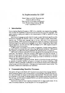
2.1.1 Energy Management Systems Energy use in organizations can be reduced 10% to 40% by implementing an effective Energy Management System (EnMS) [14]. An EnMS is an interacting series of processes. It aids an organization to systematically achieve and maintain energy management activities to improve energy performance. The EnMS applies PLAN-DO-CHECK-ACT (PDCA) model for persistent improvement. Figure 1 illustrates how use of PDCA model will leads to continuous improvement. It provides the processes and systems which are necessary in order to incorporate energy management with organizational strategy to improve energy performance [15].
Figure 1: PDCA cycle for continues improvement [16] Requirements for establishment and implementation of an energy management system is commonly being specified by International Standard ISO 50001. ISO 50001 can be applied to any system regardless of the types of energy used. It has a high compatibility
6 with ISO 9001 quality management systems and ISO 14001 environmental management systems. As shown in Figure 2, ISO 50001 is based on PDCA cycle.
Figure 2: Plan-Do-Check-Act (PDCA) cycle The PDCA management framework supports organizations to realize their energy consumption, identify opportunities for improvement, arrange projects to measure success, lessen energy costs, and reduce greenhouse gas emissions [17]. The PDCA approach can be summarized as follows [18]. Plan: conduct the energy review and establish energy performance indicators, objectives, and necessary actions to figure out opportunities for energy performance improvement. Do: implements energy management strategies. Check: determine energy performance against the energy policy objectives by monitoring and measuring key characteristics of processes and operation then the result will be reported. Act: take actions to persistently improve energy performance and the energy management systems.
7
2.2
Key performance Indicators
Key performance Indicator (KPI) generally is defined as a type of performance measurement [19]. KPI is defined much the same in many research works. In [20] and [21], KPIs is described as a variable that declares quantitatively the success or efficiency of a process or system in contradiction of a given target. KPI definition in [22] is as “A performance indicator defines the measurement of a piece of important and useful information about the performance of a program expressed as a percentage, index, rate or other comparison which is monitored at regular intervals and is compared to one or more criterion” . [23] Represents KPIs as a set of measures aiming those facets of organizational performance which are crucial for present and future success of the organization. There are also other terms describing performance of a system such as Key Result Indicators (KRIs) and Performance Indicators (PIs). KRIs are made up of aggregate data for many actions in past and covering more time interval than KPIs and do not specify how to progress the result. PIs fall between KPIs and KRIs and helps teams to align themselves with their organization’s strategy. Table 1, briefly summarize the difference between KPIs and KRIs. Table 1: The difference between KPIs and KRIs [24] KPIs KRIs Can be financial and non-financial, e.g. Non-financial measures (not expressed in Return on capital employed, and customer $s, Yen Euro, etc.) satisfaction percentage Measures mainly monthly and sometimes Measured frequently e.g. daily or 24 by 7 quarterly Acted upon by the Chief executive Officer As a summarize of progress in an organization’s critical success factor it is ideal (CEO) and senior management team to a Board All staff understand the measure and what It does not help staff or management as nowhere does it tell what you need to fix corrective action is required Responsibility can be tied down to the Commonly, the only person responsible for a KRI is the CEO. individual or team Significant impact e.g. it impacts on more than one of top Critical Success Factors A KRI is designed to summarize activity (CSFs) and more than one balanced within one CSF scorecard perspective Has a positive impact e.g. affects all other A KRI is a result of many activities managed through a variety of performance measures performance measures in a positive way Normally reported by way of an intranet Normally reported by way of a trend graph screen indicating activity, person covering at least the last fifteen months of responsible, track record etc. so a phone activity call can be made.
Any organization in order to achieve to an accurate design of performance measures, needs to distinguish carefully between KPIs, KRIs, PIs and other similar terms. It is well investigated in [25] to differentiate between these terms. However, KPIs are more featured for day-to-day and online performance measurements and can be counted as an appropriate criteria for assessing energy efficiency of the factories.
8
2.2.1 Properties and characteristics of KPIs in implementation level [26] and [27] have itemized four major key properties which need to be considered when a set of KPIs are defined: 1. Unit of measurement- for example watts, numbers, volume. 2. Type of measurements- For instance absolute or adjusted. 3. Duration of measurements- hourly, daily, weekly. 4. Boundaries- determines what is of interest of an organization to measure its assigned indicator, for instance a production line or life cycle of a product. Beside above mentioned properties, according to [23] a well-designed KPIs must follow characteristics as below: Nonfinancial measures Frequent measurements Represented on by the CEO and senior management team Declare clearly what sort of actions is required by the personnel Have a substantial impact They inspire proper actions Measures that associate responsibilities to different teams in the organization
2.2.2 General applied KPIs in production systems Every production systems according to its processes and requirements needs to design a set of relevant KPIs. To derive KPIs from production processes, [26] has introduced an iterative model. This 8-step iterative model is shown in Figure 3.
Figure 3: Steps for deriving KPIs from a production process [26] According to the Figure 3, in the first step by defining production goals and objectives all key facets of the organization should be listed. Then
9 in the second step, all possible indicators must be predicated to reflect production goals and efficiency purposes. The third step is selection of production-specific indicators. At this stage, all the personnel should cooperate to ensure data availability and responsibility to implement the indicators. Fourth step is setting the targets and is very vital as it ensures management assurance and helps liability. Reaching to a target highlights the necessity for setting new goals and objectives in order to have a continuous progress process. The most time consuming step is the fifth one. This step is implementation of indicators and comprises data gathering, calculation, assessment and interpretation of the result. To have a continuous improvement, periodic monitoring and communicating of the result has been suggested in sixth step. By establishing a system for evaluation and presentation of the result to the employees and customers a company can improve public image and increase competitiveness in the business market. Acting on the result in the seventh step is for correction of the measures in order to lead to a continuous improvement of production performance. To end with eighth step, indicators, policies, goals and will be reviewed to set and adjust new objectives and indicators. [26] has introduced several KPIs frameworks based on the production performance and suggests general KPIs for production efficiency. These KPIs are composed of numerous indicators and are summarized in Table 2. Table 2: Deriving KPIs based on the indicators [26] KPIs
Safety and environment
Production Efficiency
Quality
Production plan tracking Employees’ issues
Indicators Number of accidents at work Number of hazardous alarms Fresh water consumption Waste generated before recycling Number of penalties due to releasing waste in environment Efficiency of employees in production Infrastructure efficiency Material used (total and per product) Energy used (total and per product) Unit product time Quality of internal and external services Production shutdowns Percent of final products, which do not meet quality criteria Percent of raw material, which do not meet quality criteria Size of production losses Quality of internal and external services Percent of production orders finished late Number of penalties Percent of production orders finished ahead Complete job satisfaction of employees Lost work due to injury and illness Average length of service of employees Employees’ proposal for improvements and innovations
10 This research work investigates monitoring of general KPI schema for on-line production process. It also tries to explain results in implementation of production information systems. However, it suffers from presenting on-line data collection methods to address design of database architecture for DSS systems. To qualitatively improve manufacturing performance measures, [25] has proposed new methodology in which key performance indicators are categorized into 6 sections as shown in Figure 4.
Figure 4: Qualitative KPIs [25] This paper focuses on KPIs of the dependability where these KPIs are consisting of customer complains (due to the operational problems), on-time-in-full delivery of the product to the customers, on-time-in-full delivery from suppliers and overall equipment effectiveness (OEE). Subsequently in this paper there are some definition presented for availability, production rate and quality rate in a manufactory. The study has collected data through a real case study and has compared the data result with world-class performance. Consequently it claims that by considering actions including operators training, technical improvement in machines, proper production scheduling, redesign of the products and upgrading operational instructions, OEE will be raised.
2.2.3 KPIs in sustainable production Lowell Centre for Sustainable Production (LCSP) has proposed a sustainable production as “the creation of goods and services using processes and systems that are non-polluting; conserving of energy and natural resources; economically viable; safe and healthful for employees, communities and consumers; and socially and creatively rewarding for all working people”. This description is based on contemporary understanding of sustainable development due to its focus on environmental, social and economic aspects of companies’ activities. This definition emphasizes six central phases of sustainable production [27]: 1. energy and material use (resources) 2. natural environment (sinks) 3. social justice and community development
11 4. economic performance 5. workers 6. products The LCSP in [27] has expressed nine guiding principles in order to support better understanding of sustainable production between firms in which these principles simplify the basis for the current indicator framework (see Table 3). Concerns including products design and packaging, removal of waste, reducing of work-related risks and continuously increasing worker, development and etc. has been addressed by these principles. Table 3: Principles of sustainable production adopted from LCSP [27] 1. Products and packaging are designed to be safe and ecologically sound throughout their life cycles; services are designed to be safe and ecologically sound. 2. Wastes and ecologically incompatible byproducts are continuously reduced, eliminated, or recycled 3. Energy and materials are conserved, and the forms of energy and materials used are most appropriate for the desired ends. 4. Chemical substances, physical agents, technologies, and work practices that present hazards to human health or the environment are continuously reduced or eliminated 5. Workplaces are designed to minimize or eliminate physical, chemical, biological, and ergonomic hazards. 6. Management is committed to an open, participatory process of continuous evaluation and improvement, focused on the long-term economic performance of the firm. 7. Work is organized to conserve and enhance the efficiency and creativity of employees. 8. The security and well-being of all employees is a priority, as is the continuous development of their talents and capacities. 9. The communities around workplaces are respected and enhanced economically, socially, culturally and physically; equity and fairness are promoted.
There is a growing trend among stockholders, communities and consumers of standardized sustainability indicators that causes one to one comparisons between companies. To respond to this trend, Veleva and Ellenbecker in [27] propose a set of twenty-two core indicators in above-mentioned six phases of sustainable production. These core indicators are selected to measure common subjects in all production facilities regardless nature of production activities. Table 4 summarizes these core indicators in a nutshell.
12 Table 4: Core indicators of sustainable production [27] Aspect of SP Energy and material use
Natural environment
Economic viability
Community development and social justice
Workers
Products
1. 2. 3. 4. 5. 6. 7. 8.
9. 10.
Core indicator Fresh water consumption Material used (total and per unit product) Energy use (total and per unit product) Percent of energy from renewable Kilograms of waste generated before recycling Global warming potential (GWP) Acidification potential Kilograms of persistent, bioaccumulative and toxic (PBT) chemicals used EHS compliance costs Customer complaints and / or returns
11. Organizational openness 12. Community spending and charitable contributions 13. Number of employees per unit of product 14. Number of community-company partnerships 15. Lost workday injury and illness rate 16. Rate of employee suggested improvements 17. Turnover rate or average length of service 18. Average number of hours of employee training 19. Percent of workers who report complete job satisfaction 20. Percent of products designed for disassembly, reuse or recycling 21. Percent of biodegradable packaging 22. Percent of products with take-back policies
Metrics Liters Kg kWh % Kg Tons of CO2 Tons of CO2 Kg
$ Numbers of complaints/returns per product sale Number (1-5) % Numbers/$ # Rate Number suggestion employee Rate (years)
of per
Hours % % % %
Proposed core indicators are meant to provide a set of standard indicators which are easily applicable and implementable among a vast range of companies and sectors. As mentioned earlier, every organization to assess its performance must to evaluate desired KPIs which are stored in databases. Next chapter give brief overview on database systems which are commonly used in industrial organizations.
2.3
Databases and Database Management Systems
Data is playing a very important role in any businesses. Data is being used and collected almost everywhere, from businesses trying to determine consumer to manufactories trying to collect data from electrical devices. Data requires robust and
13 secure software that can store and process it rapidly. A reliable database addresses this needs. Database software application is universal and used by the billions of daily users. This section provides an overview of the fundamentals of database management systems and information models.
2.3.1 Database By the advent of databases, they have been among the most researched domains in computer science. According to [43] database is a repository of data, aimed to support storage, retrieval and maintenance of data. There are different type of databases to cover various industry requirements. A database may store diverse type of data such as binary files, documents, images, videos, relational data an etc. Size and complexity and structure of a database may differ according to the requirements of the business. Structure of a database means the data types, relationships, and constraints that apply to the data. Researchers in [44] have stated that every database has the following properties: A database should characterize some facet of the real world, Changes must be reflected in the database. A database is a logically integrated collection of data which has some inherent meaning. A random collection of data cannot be counted as a database. A database specifically is designed and populated with data for a particular purpose to satisfy a group of users. A collection of concepts that can be used to describe the structure of a database is called data model [44]. Database design is usually based on proper data models. Models are basic notions of real-world events or conditions enabling users to discover the characteristics and relationships of entities. A database model is commonly known as a collection of logical concepts to exemplify the structure of data and the data relationships in the database. Database models are defined within two classes [44],[45],[46] : • Conceptual model: This model concerns what could be declared in the database while maintain the logical nature of the data. • Implementation model: focuses on how in the database information could be represented or how to implement the data structures in order to represent the model. Hierarchical database model, the network database model, and the relational database model are examples of implementation model.
2.3.2 The Relational Database Model A relational database is a type of database made of a collection of tables for storing data in which the tables are organized and structured according to the relational model. Figure 5 illustrates an example of relational data model.
14
Figure 5: Example of a relational database model- adopted from [43] [47] and [49] define the relational model as a database model created based on firstorder predicate logic. In the relational model of a database, data altogether is represented in terms of tuples and assembled into relations. Data in a separate table represents a relation. A tables may have also relationships with other tables. Each table schema must have a column called primary key to uniquely identify each rows of the table. Rows in different tables can have relationship through a foreign key which is a column in one table pointing to the primary key of another tables. Structured Query Language (SQL) is a language that makes it possible for users to manipulate relational data. One of the advantage of using SQL is that users do not need to know how to retrieve information, they should only specify the information they want. The RDBMS is responsible for providing the access to retrieve the data [43], [53]. An example of SQL query has been expressed as below: select Date, Route, kpi_value from Table where Route=A-20''
2.3.3 Database Management Systems As mentioned earlier while a database is a warehouse of data, a database management system, or in short DBMS, is defined in [43] as “a set of software tools that control access, organize, store, manage, retrieve and maintain data in a database. In practical use, the terms database, database server, Database, database system, data server, and database management systems are often used interchangeably”. The most common database systems used in production are relational database management systems (RDBMS). RDBMS play a vital role in many industries including manufactory, health, banking and etc. Edgar F. Codd, inventor of relational model for databases, has proposed a set of thirteen rules to identify what is required from a DBMS to be considered a RDBMS. Table 5 has summarized these rules.
15 Table 5: Codd's twelve rules for RDBMS-Adopted from [51]. Rule No. 0
The Foundation rule
1
The information rule
2
The guaranteed access rule Systematic treatment of null values Active online catalog based on the relational model The comprehensive data sublanguage rule The view updating rule
3 4
5 6 7 8 9
Rule
High-level insert, update, and delete Physical data independence Logical data independence
10
Integrity independence
11
Distribution independence
12
The nonsubversion rule
Description RDBMS to store data must only use its relational capabilities. All information in a RDB (including table and column names) is represented in only one way, namely as a value in a table. All data must be accessible. The DBMS must allow each field to remain null. The system must support an online, inline, relational catalog that is accessible to authorized users by means of their regular query language. The system must support at least one relational language. All views that are theoretically updatable must be updatable by the system. The system must support set-at-a-time insert, update, and delete operators. Changes to the physical level must not require a change to an application based on the structure. Changes to the logical level (tables, columns, rows, and so on) must not require a change to an application based on the structure. Integrity constraints must be specified separately from application programs and stored in the catalog. The distribution of portions of the database to various locations should be invisible to users of the database. If the system provides a low-level (record-at-a-time) interface, then that interface cannot be used to subvert the system.
2.3.4 Drawbacks of relational databases Generally speaking databases including RDBs suffer from following issues: Design cycle of DB is complex Data integration especially when data model is different is difficult [54]. Exploring the names of entities and their relations to formulate a SQL query is problematic [55]. Discovering the semantic of data model for domain users is a tricky task. In order to overcome above-mentioned problems, researcher have proposed design of ontologies over relational databases. In next chapter ontology as a semantic model has been described.
16
2.4
Ontologies
The next generation of manufacturing systems known as smart factories are being implemented based on knowledge management tools to apply the artificial intelligence for developing production processes. Manufacturing domain has been defined by [56] as a group activity of product, process and resource concepts. Therefore, working with manufacturing domain means dealing with those concepts. For instance taking control over them as well as the interrelation happening between them. According to the [56], there are three main elements which cause interrelation between concepts of manufacturing domain. These elements are information systems, rules and a common vocabulary. Semantic tools such as ontologies address this sort of issues. Gruber in [57] describes ontology as “an explicit specification of a conceptualization”. This definition is derived from the Artificial Intelligence (AI) literature on Declarative Knowledge, which is about the formal representation of the knowledge [58]. In AI field, formal logical languages namely first-order predicate calculus, are used to expressively describe models of the world. This is due to the uncertainty of the natural languages for machine interpretation [59]. An ontology uses a proper and shared language to represents knowledge as a hierarchy of concepts within a domain to express the types, properties and interrelationships of those concepts [60], [61]. Therefore ontologies are considered as the structural frameworks to shape the information in an organized and unified way. Ontology is providing a shareable vocabulary which can be understood by both human and machines. An ontology uses five fundamental elements to model a domain: Classes: the elements that represent concepts of the domain; for example, in the family domain, Father, Mother, Son and Daughter are the concepts. Relations: the relationships between concepts of the domain; generally are hierarchies of classes such as a Father is subclass-of Family member. On the other hand, Family member is supper class for Father. Functions: class properties such as is-Father-of (x, y) means x is the father of y. Axioms: logical assertions including rules. For instance an axiom of the family domain ontology could be that every father must have at least a son or a daughter. Instances: objects that belong to a class; for example, Peyman is-a Son means Peyman is an instance of the class called Son. Scientists in Stanford University have categorized the main reasons behind ontology developments as below [64]: 1. “To share common understanding of the structure of information among people or software agents 2. To enable reuse of domain knowledge 3. To make domain assumptions explicit 4. To separate domain knowledge from the operational knowledge 5. To analyze domain knowledge” Sharing common understanding of the structure of information among people or software agents is counted as one of the most important targets in any ontology development (Musen 1992; Gruber1993). For instance, consider that several different web sites have manufacturing information to provide some services for clients. If the terms used in underlying ontology of these web sites are the same, computer agents can
17 aggregate information which are extracted from all those web sites to build a super ontology model. Then agents can take advantages of this universal model to answer user’s queries. Enabling reuse of domain knowledge is one of the motivations behind ontology research. It means that if an ontology is designed by a group of expert for one particular domain, that ontology could be also used by other groups working in the same domain or separately developed ontologies can be merged to build a more complex ontology to satisfy bigger group of users working on almost the same domain. Making explicit domain assumptions provides this possibility to change and modify the domain assumption if knowledge over the domain changes in contrast Hard-coding programming for domain assumption is almost impossible to be changed. Separating the domain knowledge from the operational knowledge is the other beneficial use of ontologies. To clarify this concept more, for instance a product assembling task can be defined according to the required features and implement a program to do this task independent of the products and the involving components (McGuinness and Wright 1998). Then a PC-components ontology can be developed to configure the process. Analyzing domain knowledge is feasible when a declarative specification of the domain terms are available. Analysis of terms is appreciated when to reuse existing ontologies and try to extend them (McGuinness et al. 2000). Typically design of domain ontology is not a goal alone. Building an ontology provide this chance to define a set of well-structured data for other programs or agent to use. Domain-independent applications, and software agents use ontologies as intermediate data. For example in this thesis work, ontology is being used to retrieve data from RDBs. Many projects have developed standardized ontologies that domain experts can use information in their own fields. Medicine and health care, for instance, has produced enormous and standardized vocabularies known as SNOMED [65] and the semantic network of the Unified Medical Language System (Humphreys and Lindberg 1993). Comprehensive multi-purpose ontologies are developing as well. As an example, the United Nations Development Program and Dun & Bradstreet is developing the UNSPSC ontology which offers terminology for products and services [66]. In many other researches ontologies has been used for enterprise managements [62], [63] and supply chain configuration and deployment [67], [68].
2.4.1 Methodologies for design of domain ontologies There is not a unique way or methodology for developing ontologies. A domain ontology can be designed by different experts differently while carrying the same concept. However to develop an ontology in [64] seven steps is proposed. These steps are named as below: Step 1. Define the domain and scope of the ontology Step 2. Reusing ontologies developed for the same field Step 3. Itemize important terms in the ontology Step 4. Define class hierarchies Step 5. Define the object and data properties of classes Step 6. Define the restrictions and constraints for properties Step 7. Create instances
18
2.4.2 OWL 2 Web Ontology Language OWL 2 Web Ontology Language is one of the most applied ontology languages to create ontologies. OWL 2 is an extension and revision of the OWL 1 Web Ontology Language established by the W3C Web Ontology Working Group and published in 2004 [70]. The languages are characterized for the Semantic Web by formal RDF/XML based serializations.
Figure 6: Semantic Web stack [69] Figure 6 illustrates the architecture of the Semantic Web by the Semantic Web Stack. In this stack, XML is a base syntax of structured documents and is not made of any semantic constraints. XML Schema defines the constraints structure of XML documents. The Resource Description Frame work (RDF) is a data model of resources with their relationships declared by XML syntaxes [71]. It offers very basic semantics for the data model. RDF Schema defines the attributes and types of the RDF resources by providing generic semantics for them [72]. OWL increases more vocabulary and expressivity to describe attributes and types, such as disjointness, cardinality in types and symmetry in attributes. OWL includes more advanced features to characterize domain semantics compared to the XML, RDF and RDF Schema. OWL 2 ontologies can be saved and used according to different syntaxes. Different syntaxes of OWL 2 has compared in Table 6. RDF/XML is the main exchange syntax for OWL 2. Therefore all OWL 2 tools must support RDF/XML. Table 6: OWL 2 Syntaxes comparison Syntax name RDF/XML OWL/XML Functional Syntax
Status Purpose Mandatory Interchangeable and supported by all OWL 2 tools Optional Easier for being processed by using XML tools Optional Easier to meet the requirements of formal structure of ontologies
19 Manchester Syntax Turtle
Optional
Easier to read/write Description Logic (DL) Ontologies
Optional
Easier to read/write RDF triples
As an example an ontology written in RDF/XML syntax can be stated as below:
By this assertion an ontology class named Robot has been created.
2.4.3 Comparison between OWL 2 and OWL 1 As mentioned earlier, OWL 2 is an extension and revision of the OWL 1 Web Ontology Language established by the W3C Web Ontology Working Group. OWL 2 in comparison with OWL 1 has been equipped by more features. According to the [73] these feature can be categorized in following list: 1. Syntactic sugar to make some common statements easier to express. 2. New constructs that increase expressivity. 3. Extended data types capabilities. Table 7 explains each features in more details: Table 7: Comparison between OWL 2 and OWL 1- adopted from [73] 1. Syntactic sugar OWL1 OWL2 While OWL 1 provides means to DisjointUnion Defines a class as the union of other classes, all of which define a set of subclasses as a disjoint and complete covering of are pairwise disjoin a superclass by using several axioms, this cannot be done concisely. While OWL 1 provides means to DisjointClasses state that two subclasses are States that all classes from the set are pairwise disjoin disjoint, stating that several subclasses are pairwise disjoint cannot be done concisely. While OWL 1 provides means to NegativeObjectPropertyAssertion assert values of a property for an NegativeDataPropertyAssertion States that a given property does not hold for the given individual, it does not provide a construct for directly asserting individuals values that an individual does not have (negative facts). 2. New constructs that increase expressivity OWL 1 OWL 2 ObjectHasSelf
20 A class expression defined using OWL 1 does not allow for the an ObjectHasSelf restriction denotes the class of all definition of classes of objects that objects that are related to themselves via the given are related to themselves by a given property, for example the object property class of processes that regulate themselves While OWL 1 allows for ObjectMinCardinality, ObjectMaxCardinality, restrictions on the number of and ObjectExactCardinality (respectively, DataMinCardinality, DataMaxCardinali instances of a property, e.g., for defining persons that have at least ty, and DataExactCardinality) Allow for the assertion of minimum, maximum or exact three children, it does not provide means to restrain qualified cardinality restrictions, object (respectively, a the class or data range of the data) properties instances to be counted (qualified cardinality restrictions), e.g., for specifying the class of persons that have at least three children who are girls. In OWL 2, both qualified and unqualified cardinality restrictions are possible. While OWL 1 allows assertions ReflexiveObjectProperty The OWL 2 construct ReflexiveObjectProperty allows that an object property is it to be asserted that an object property expression is symmetric or transitive, it is globally reflexive - that is, the property holds for all impossible to assert that the property is reflexive, irreflexive or individuals asymmetric. IrreflexiveObjectProperty The OWL 2 construct IrreflexiveObjectProperty allows it to be asserted that an object property expression is Not available for OWL 1 irreflexive - that is, the property does not hold for any individual Not available for OWL 1. AsymmetricObjectProperty The OWL 2 construct AsymmetricObjectProperty allows it to be asserted that an object property expression is asymmetric. While OWL 1 provides means to DisjointObjectProperties The OWL 2 construct DisjointObjectProperties allows state the disjointness of classes, it it to be asserted that several object properties are is impossible to state that pairwise incompatible (exclusive); that is, two properties are disjoint. individuals cannot be connected by two different properties of the set. DisjointDataProperties allows it to be asserted that several data properties are pairwise incompatible (exclusive) ObjectPropertyChain The OWL 2 construct ObjectPropertyChain in a SubObjectPropertyOf axiom allows a property to be defined as the composition of several properties. HasKey An HasKey axiom states that each named instance of a class is uniquely identified by a (data or object)
Not available for OWL 1 OWL 1 does not provide a means to define properties as a composition of other properties OWL 1 does not provide a means to define keys. However, keys are clearly of vital importance to many
21 property or a set of properties - that is, if two named applications in order to uniquely instances of the class coincide on values for each of key identify individuals of a given class by values of (a set of) key properties, then these two individuals are the same properties. The OWL 2 construct HasKey allows keys to be defined for a given class. 3. Extended datatype capabilities OWL 1 OWL 2 OWL 1 provides support for only DatatypeRestriction DatatypeRestriction also makes it possible to specify integers and strings as datatypes restrictions on datatypes by means of and does not support any subsets constraining facets that constrain the range of values of these datatypes. For example, allowed for a given datataype, by length (for strings) one could state that every person e.g., minLength, maxLength, and minimum/maximum has an age, which is an integer, but value, e.g., minInclusive, maxInclusive. Extended could not restrict the range of that datatypes are allowed in many description logics and datatype to say that adults have an age greater than 18. OWL 2 are supported by several reasoners provides new capabilities for datatypes, supporting a richer set of datatypes and restrictions of datatypes by facets, as in XML Schema.
DatatypeDefinition allows to explicitly name a new datatype
DataIntersectionOf/DataUnionOf/ DataComplementOf In OWL 2, combinations of data ranges can be constructed using intersection (DataIntersectionOf),union ( DataUnionOf), and complement (DataComplementOf) of data ranges.
OWL 1 allows a new class to be defined by a class description, but it does not offer means to explicitly define a new datatype. For ease of writing, reading, and maintaining ontologies, OWL 2 provides a new construct to define datatypes; this is particularly useful if the same datatype is used multiple times in an ontology. While OWL 1 allows a new class to be constructed by combining classes, it does not provide means to construct a new datatype by combining other ones. In OWL 2 it is possible to define new datatypes in this way.
OWL 1 proposed three major dialects, OWL DL and OWL Full and OWL Lite. However, it was being appeared that this was not adequate to address requirements identified by deployments of OWL ontologies. Some of these requirements are summarized as [73]:
Many applications, particularly use very large ontologies while OWL 1 dialects are proper for lightweight ontologies Numerous applications containing classical databases are dealing with interoperability of OWL with database technologies and tools.
22
Other applications are concerned with interoperability of the ontology language. Ontology may be used to query large datasets where OWL 1 dialects cannot be enough expressive for this purposes.
OWL 2 in order to address above requirements has proposed three sublanguages: OWL 2 EL, OWL 2 QL and OWL 2 RL. Characteristics of each sublanguages is expressed briefly in Table 8. Table 8: Characteristics of OWL 2 sublanguages- adopted from [73] OWL 2 EL
1. Suitable for applications where very large ontologies are needed 2. Expressive power can be traded for performance guarantees 3. Polynomial time algorithms for reasoning tasks
OWL 2 QL
1. Suitable for applications where relatively lightweight ontologies are used 2. Using standard relational database technology 3. Access the data directly via relational queries (e.g., SQL)
OWL 2 RL 1. suitable for applications where relatively lightweight ontologies are used 2. Using ruleextended database technologies operating directly on RDF triples. 3. operate directly on data in the form of RDF triples
2.4.4 Reasoning in Ontologies Reasoning in ontologies is one important reason that a specification needs to be formal one. Reasoning means deriving extra facts that are not expressed in ontology clearly. For example, if X is subset of Y and Y itself is subset of Z, then reasoning indicates that X is subset of Z as well. A reasoner is a piece of software performing reasoning tasks such as inferring logical results from a set of asserted facts in the ontology. There are different reasoners such as FaCT++, Pellet, HermiT and Quest. Among all, Pellet is one of the most common reasoning engines that is used for reasoning OWL models. Pellet provides reasoning with the full expressivity of OWL-DL and has been extended to support OWL 2. According to the [76], a few expected task from a reasoner are as:
Satisfiability of a concept - determine whether a description of the concept is no contradictory Subsumption of concepts - determine whether concept C subsumes concept D Consistency of ABox with respect to TBox - determine whether individuals in ABox do not violate descriptions and axioms described by TBox Check an individual - check whether the individual is an instance of a concept
23
Retrieval of individuals - find all individuals that are instances of a concept Realization of an individual - find all concepts which the individual belongs to it
The target of this thesis work is to implement an ontology over a RDB database to solve some drawbacks of the databases as it has been mentioned in section 2.3.4. To meet this target Quest reasnoer described in [77] has been selected. Quest supports RDFS and OWL 2- QL and it is SPARQL-to-SQL query revising. Quest is able to generate effective SQL queries similar to the SQL queries that can be written by a database expert. This is very important since DB engines can have unsatisfactory performance if the SQL they receive is not well-structured. The queries created by Quest are well-structured and allow the underlying database to correctly execute the SQL query [74]. The main features of Quest is listed as below [77]:
SPARQL 1.0 support RDFS and OWL 2 QL inference regimes Support for PostgreSQL, MySQL, H2, DB2, SQL Server, Teiid and Oracle. Other JDBC sources may work too. Support for database federation (a.k.a. database virtualization) systems such as Teiid. Support for OWLAPI 3 and Protégé 4.3 Support for Sesame 2.7 and Sesame Workbench SPARQL end-point (through Sesame’s Workbench)
2.4.5 Ontology APIs There are few APIs for ontology developments. An ontology API is a Java API and enables implementation for creating, manipulating and serializing OWL Ontologies. Jena API, OWL API and Protégé API are among the most common used APIs in ontology science. Table 9 provides fundamental features of each above-mentioned APIs. Table 9: Basic features of three different APIs used in ontology domain- adopted from [80],[81],[82]. Jena API The most widely used Java APIs for RDF and OWL Can be used to create OWL constructs, axioms and run inferences. General purpose RDF API plus an OWL API, plus SPARQL processor, reasoning support
OWL API It is not RDF-friendly
Protégé API Extension of the OWL API
Not possible to apply SPARQL queries any time soon Is a Java API and reference implementation for creating, manipulating and serializing OWL Ontologies
The Protégé-OWL API does not sit on top of Jena, good for newcomers Protégé API is the most complete, and has good compatibility with Protégé
24 Providing services for Working with reasoners Complicated because of the model representation, such as FaCT++, HermiT, API’s flexible but lowlevel nature parsing, database Pellet and Racer persistence,
Easy/reasonable to use
Loading ontologies is easy, Protégé API includes most running SWRL of the Jena properties more complex
Straight forward Write both java programs programming and also use commandline inputs
2.5
Protégé is also an openjava source, Java tool that provides an extensible architecture for the creation of customized knowledgebased applications.
Ontology-Based Data Access
As mentioned earlier, ontologies are being considered as a reliable tool for providing a shared conceptualization of the domain of interest. Ontologies can be also applied in many other areas such as enterprise data integration and the semantic web. Specifically, in many of the above-mentioned fields, use of ontologies supports to determine what it is called Ontology-Based Data Access (OBDA). According to the [88] , OBDA can be simply explained as follows: There is a set of pre-existing data sources which defines the data layer of the information system, and there is a need to build a service above this layer, intending to provide a conceptual view of data to the clients of the data sources. In particular this conceptual view is presented in form of an ontology. This represents the exclusive access point for the communication between the clients and the data sources of the system. Data sources and ontology are independent from each other. Figure 7 illustrates this concept.
Figure 7: Ontology-Based Data Access (OBDA) - Adopted from [89] To clarify more, the goal is to link the ontology to a set of data that is gathered separately and is not necessarily structured to be matched with ontology. Hence, in OBDA, the ontology describes abstractly the domain of interest, independent from the
25 way data sources are maintained in the system’s data layer by itself. It means that the ontology and the data sources have different perceptions, and are created based on different languages. For instance, the ontology is built based on logical languages while the data sources are commonly represented based on the relational data model. Given the fact and according to the [88], the specific issues in OBDA development can be summarized as below: 1. Domain ontologies provide a conceptual view for its clients. The semantic complexity of the ontology depends on the conditions of the domain of interest. Thus one of the main challenges in ontology design is to figure out a proper ontology language. The selected language should provide a balance between its expressive abilities and its computational simplicity for reasoning over both the ontology, and the underlying sources storing the obtained data from the domain. 2. The sources are usually populated with large amount of data. Consequently a technology to provide an efficient access to large amount of data need to be considered. Relational database technology is one of the best options to meet this requirement. Hence, the focus of the OBDA system is in data which are maintained in the RDBMS. 3. Since the ontology and data resources are existed and developed independently from each other, the ontology and data sources need to be mapped with each other. Therefore, in OBDA, the mapping is a tool in which it defines how to link ontology to the data or vice versa. In other words, mapping determines in what way to restructure the form of data in the sources to the ontology expressions. In addition the language used for mapping must address the mismatch problem between the data model of the source and the ontology model. The main reason behind building an OBDA system is providing a high-level services for the clients of the information systems. Query-answering is the most significant service that can be offered to the clients [88]. Clients define their queries in SPARQL (ontologies query language). Subsequently, the system should reason both ontology and the mapping and then must convert the request into appropriate queries delivered to the data sources.
2.5.1 Mapping tools As mentioned in the previous section, a suitable mapping tool for OBDA need to be selected. There are few tools available such as -ontop-, D2RQ, R2O, MAPONTO and etc. Each of them has its own specific features. Table 10 summarizes specification of some mapping tools which have been investigated in this thesis work.
26 Table 10: Features of some mapping tools-adopted from [90], [91] Tool
Ontology Language
-ontop-
OWL2-QL
D2RQ
RDF, DAML+OI L
R2O
RDF/OWL
MAPONT O Relational. OWL
OWL RDF/OWL
RDBMS Any RDBMS offering JDBC access Any RDBMS offering JDBC or ODBC access Any SQL implementing RDBMS Any SQL implementing RDBMS DB2, MySQL, Oracle
Semantic query language SPARQL
Degree of Automatio n Manual
RDQL
Both manual and automatic Manual
None None Any language that can query an OWL ontology
Semiautomatic Automatic
Table 11 also declares some other details of the above mentioned tools in terms of their methodology techniques. Table 11: Methodology of mapping tools- adopted from [90] , [91] Tool
Methodology Components Consistency User Technique mapped Checks Interaction Language for DB tables, Yes, through Graphical mappings columns, OWL API interface -ontopdescription primary/foreign Language for DB tables, Yes, through No graphical mappings columns, the Jena API interface D2RQ description primary/foreign Ontology DB tables, No graphical populated columns, No interface R2O with foreign keys instances Shortest path The user should finding provide between DB tables and No correspondences MAPONO concepts of columns between the database ontology and ontology Creation of DB tables, No, one columns, ontology None Relational.OWL class per primary/foreign is described database keys, datatypes in OWL Full
27 After evaluating capabilities of the mappings tools according to the Table 10 and Table 11 and in order to meet the three issues which are described in the previous section, -ontop- is selected as the best fit for the target of this thesis work.
2.6
Overview of Service Oriented Architecture (SOA)
2.6.1 Definition of Service Oriented Architecture (SOA) Many definitions is suggested for SOA. In [30] SOA is defined as: “A service Oriented Architecture is a set of components which can be invoked and whose interface descriptions can be published and discovered.” Helmut Petritsch in [31] by using result of [32] trying to provide a more sensible definition for SOA as: “SOA is an architectural style whose goal is to achieve loose coupling among interacting software agents. A service is a unit of work done by a service provider to achieve desired end results for a service consumer. Both provider and consumer are roles played by software agents on behalf of their owners.” Figure 8 illustrates main elements of Service Oriented Architecture.
Figure 8: Main collaborating elements in SOA [29] As it is shown in Figure 8 there are three roles in SOA:
Service consumer: The service consumer is an application or a software module that consume a service. According to the interface contract, the service consumer performs assigned service. Service provider: The service provider is an application that receives and executes requests from consumers. Service provider publishes its services to the service broker, as a result, discovering the matching service would be possible for service consumer. Service registry or Service broker: A service broker is an application which enables service discovering. It is responsible for availability of the service information for any potential service consumer [33], [29].
According to the Figure 8, SOA is consisting of three main operations: Publish: A service description must be published in order to be accessible, discovered and invoked by a service consumer.
28 Find: A service requestor finds an appropriate service by querying the service registry. Bind and invoke: The service consumer, once obtaining the service description, continues to invoke the service based on the contained information in the service description. There is no perfect definition of SOA in literature. Nevertheless, it is possible to classify certain key features which are broadly considered to apply to all SOAs. SOA main characteristics is simplified in Table 12. Table 12: Principles and characteristics of SOA adopted from [39] and [40] Characteristics
Standardized interface Loose connection
Functional abstraction Reusability autonomy Statelessness Discovery availability
Comment
Standardized interface declares how the service can be used, which type of data is needed and how certain guidelines can be applied. Services are loosely connected together, establishing one process. The principle is defined to reduce the dependency of the services while still guarantees interoperability between them. Services hide logics from the exterior world. Services are reusable by other parties and applications. This idea must be considered in at the development phase. Service are working independent of external services able to manage all the necessary logic, resources and environment. Services lessen resource consumption by deferring the information management when it is necessary. and Services are available for all consumers via a repository. Repository contains service interface and implementation specifications and stores all the information required by a consumer in order to request a service.
2.6.2 Web Services Web service is a realization and the most popular implementation of the SOA. It is important to understand that the SOA is an architectural model that is independent of any technology platform. As the name indicates, web services offers services over the web [34]. Yet, The W3C’s Web Services Architecture Working Group has proposed a widely accepted definition for Web Service as [35]: “A Web service is a software application identified by a URI, whose interfaces and bindings are capable of being defined, described, and discovered as XML artifacts. A Web service supports direct interactions with other software agents using XML-based messages exchanged via Internet-based protocols.” Web Services Protocols and Technologies: The web services is built on a set of standards that are widely accepted and used. This common standards enables clients and services to communicate and realize each other across a wide range of platforms and upon
29 language restrictions. Some of these protocols and technologies that establish these web services has been briefly described as below:
Hypertext transfer protocol [HTTP]: HTTP is common standard that is implemented in various systems, providing issues of interoperability. By applying HTTP in web services, all the machines that are able to be connected to the internet can become a consumers of web services. Security of web service communication is other advantage of using HTTPS protocols [34]. Extensible Markup Language [XML]: XML as a platform-independent language which is understandable across different systems. It is the communication language used on the protocol. XML describes data to be exchanged on the Web [36]. Web Services Description Language [WSDL]: WSDL is an XML document that encloses description of the web service’s interface. A request to web service is defined via WSDL [36]. Simple Object Access Protocol [SOAP]: SOAP is an XML-based protocol for exchange of information between clients and services in a distributed environment [37]. Universal Description, Discovery and Integration [UDDI]: is a directory service. Businesses can register and explore for Web services via UDDI. It uses WSDL documents to define interfaces to web services [38]. There are several web services architecture and frameworks offered for datainterchange between client and server. The two commonly used web services architecture are SOAP and REST. SOAP Web Service: SOAP Web Services are based on SOAP. SOAP is an XML based format and a standard protocol specification for information exchange. Web service and client Communicate with each other by using XML messages. SOAP defines the rules for communication similar to all the tags that should be used in XML [37].
2.6.3 SOA in smart factories SOA models are being successfully applied to the shop-floor of the smart factories [83]. Smart factories are equipped with devices which are able to offer their functionalities as a service thus SOA platforms can easily integrate them. SOCRADES is an example project implemented by means of the web service enabled devices is developed a platform that powerfully integrates the Enterprise systems with the shopfloor [84], [85]. This platform can be used as an elementary block where energy efficient services can be built upon it. Enterprise applications nowadays can be directly connected to devices, without using the device drivers. Devices peer to peer communication will promote application of SOA at the device layer. Moreover, usage of semantics in web services [86] provides novel opportunities for functionality discovery and collaboration of SOA in modern manufactories. Web services are perfectly able to be run natively on embedded devices, fascinating interoperability with other components in the shop-floors.
30
Figure 9: SOA-based production line [87] SOA can be implemented for energy efficiency purposes in smart factories for monitoring and control of devices. Figure 9 illustrates that performance of a SOA-based production line is constantly being monitored thanks to its assigned KPIs. In addition the involving machines themselves are able to publish the results of the measurement as a web service to other parties [87].
31
3. Methodology
This chapter provides overview of the tools and methods which are used for implementation of OBDA application for cross-domain access of energy efficiency KPIs. Figure 10 illustrates the overall architecture of the middleware which facilitates OBDA.
Figure 10: Overall architecture of the proposed middleware for OBDA Table 13 lists required technologies and tools for implementation of this middleware. Each of them is separately discussed in the next sections. Table 13: Technologies and Tools used in implementation No. 1 2 3 4 5 6 7 8
Tool/Technology JAXB OWL 2 SPARQL Protégé OWL API -ontop- with Quest Java Java Runtime Enviroment
Version 2.2.7 QL 1.0 4.3 2.0 1.9 SE 7 7
9 10 11 12
Apache CXF Apache Tomcat SOAP WSDL
2.7.10 7 1.1 1.1
Comment XML parser Ontology language Query language for ontology Ontology editor Java library for ontologies Mapping tool Eclipse Kepler IDE Used for web service development Server Protocol Service contract
32
3.1 Java Architecture for XML Binding Extensible Markup Language (XML) is a widely accepted language that expresses a set of rules to encode documents in a format that is readable for both human and machines. It is a W3C recommendation and its specification is defined in the XML 1.01. Java Architecture for XML Binding or in short JAXB2 is a technology that provides access to an XML document from a Java program. JAXB helps developers to exchange data across the Internet thanks to XML which is developed as the standard for transforming data in disparate systems. JAXB functions under Java technology. This relation is particularly important for Web services, where users need to have access to java applications The first step for using the JAXB is to bind the XML document schema into a set of Java classes. A schema is an XML specification that organize relationship between components of an XML document. For example, a schema identifies the orders of elements in an XML document and theirs attributes to other elements. If An XML document has a schema, it has to follow that schema to be counted as a valid XML document. JAXB needs the XML schema and it functions based on this Schema
3.2 Web Ontology Language 2 The OWL 2 Web Ontology Language or briefly OWL 2, is an ontology language. OWL 2 ontologies provide classes, properties, individuals, and data values .OWL 2 ontologies can be used beside information written in RDF. The ontology and middleware application for OBDA is a lightweight application which need to have access to RDB. Given the fact and according to the comparisons provided in literature review, in this thesis work OWL 2 QL sublanguage is selected for ontology design.
3.3 SPARQL SPARQL Protocol and RDF Query Language or briefly SPARQL is a query language providing possibility for users and applications to interact with ontologies. SPARQL was standardized in 2008 by the World Wide Web Consortium (W3C) [78]. SPARQL is the standardized query language for RDF-based ontologies, the same way SQL is the standardized query language for relational databases. There are some similarities between SPARQL and SQL because SPARQL shares several keywords such as SELECT, WHERE, etc. In addition SPARQL adds new keywords that does not exist in SQL world such as OPTIONAL, FILTER and etc. RDF is a triple comprised of a subject, predicate and object. A SPARQL query consists of a set of triples where the subject, predicate and/or object can carry variables. The idea is to match the triples in the SPARQL query with the existing RDF triples and find the equivalent values for the variables. A SPARQL query is executed on a RDF dataset, which can be a RDF database, or on a Relational Database to RDF system. A simple example of SPARQL query can be as below: 1 2
XML 1.0 http://www.w3.org/TR/REC-xml/ [Accessed on 14.07.2014] JAXB http://www.oracle.com/technetwork/articles/javase/index-140168.html [Accessed on 17.07.2014]
33
DATA : "SPARQL For Ontologies". Query: SELECT? title WHERE { ?title. } Result: "SPARQL For Ontologies"
In this thesis work the request of the clients as mentioned earlier are XML documents. The desired information in XML document is parsed by JAXB and then will be converted to SPARQL.
3.4 Protégé The ontology in this thesis work is designed by Protégé. Protégé is a free and open source ontology editor and knowledge-based framework. Protégé was developed by Stanford Centre for Biomedical Informatics Research at the Stanford University. Initially, it was a small application planned for a medical domain. More recently, Protégé is actively supported by a strong community of users and developers that field questions, write documentation, and contribute plug-ins. The original goal of Protégé was to reduce the knowledge acquisition process by minimizing the role of the knowledge. Protégé completely supports the OWL 2 Web Ontology Language and RDF specifications from the W3C. Protégé is built based on Java, is extensible and offers a plug-and-play environment that makes it a flexible base for quick prototyping and application development. Protégé’s plug-in can be modified to shape both simple and compound ontology-based applications. Developers can integrate the output of Protégé to create a vast range of intelligent systems [79]. Protégé aids the users to:
Load/save OWL and RDF ontologies Define and edit classes, properties, and SWRL3 rules Outline logical class characteristics as OWL expressions Execute reasoners Edit OWL instances for Semantic Web markup
3.5 –ontop-ontop-4 is a platform for querying databases as virtual RDF graphs via SPARQL. It's very fast and is packed with convenient features that helps to deploy it in many use case. Features include:
3 4
Supports for SPARQL 1.0 Intuitive and powerful mapping language
SWRL http://www.w3.org/Submission/SWRL/ [Accessed on 19.07.2014] -ontop- http://ontop.inf.unibz.it/ [Accessed on 19.07.2014]
34
Supports DBMS Friendly with DBMS integration tools Compatible with OWL API Integrated with Protégé 4.x
-ontop- is composed of:
Quest5 a fast reasoner and SPARQL query engine over RDBMS that uses very efficient SPARQL to SQL query converting techniques, providing 10 times better performance than other SPARQL engines. Quest supports OWL 2 QL reasoning. -ontopPro6- A plugin for Protégé 4 that supports a mapping editor and integrates Quest into the Java and Protégé platform.
3.5.1 Quest mapping syntax To provide OBDA access, the first step is to map the ontology classes to the tables of DB. These mapping process can be done with Quest mapping techniques provided in Quest engine. Figure 11 shows the application of Quest in presence of ontology and mappings set to provide OBDA.
Figure 11: Application of Quest for providing OBDA. Adopted from [74] A mapping must contain one data source. The data source means the database that encompasses the data of the system and the queries will be executed over it. Data sources in -ontop- are recognized via a URI and are identified by JDBC connection. Each mapping has one or more mapping axioms. One mapping axiom is defined as a pair of source and target. The source is a SQL query over the database and the target is a triple template based on classes and properties which are created in ontology. Target
5 6
Quest http://ontop.inf.unibz.it/?page_id=7 [Accessed on 19.07.2014] ontopPro http://ontop.inf.unibz.it/?page_id=2 [Accessed on 19.07.2014]
35 address column names used in the source query. For instance, the syntax below is a valid Quest mapping: target :db1/{id}/{kpi_value}/{equipment} a :Robot_1 ; :hasTimeStamp {time_stamp} ; :energyConsumption {kpi_value} . source select id,equipment,kpi_value,time_stamp from enrgyConsumption
It should be mentioned that the target of a mapping is similar to RDF triples in turtle syntax7 and is written as an RDF subject-predicate-object (SPO) graph. However –ontopdevelopers has adapted the Turtle syntax to express mapping assertions in target.
3.6 Java Java is a class-based and object-oriented programming language. In Java, everything is seen as an object therefore Java can be easily extended since it is based on the object model. Java applications are typically compiled to class file that can be run on any Java virtual machine (JVM) regardless of computer architecture. Java is one of the most popular programming languages in use, especially for client-server web applications. To write Java programs, a text editor is needed. Eclipse is an integrated development environment (IDE). It contains a workspace and many plug-ins system to customize the environment. In this work, Eclipse Kepler8 is used to develop java application.
3.7 OWL API The OWL API9 is an open source Java API and is used for creating, manipulating and serializing OWL Ontologies. The latest version of the OWL API supports OWL 2. The OWL API includes components as below:
An API for OWL 2 and an efficient in-memory reference implementation RDF/XML parser and writer OWL/XML parser and writer OWL Functional Syntax parser and writer Turtle parser and writer Reasoner interfaces for working with reasoners such as FaCT++, HermiT, Pellet and Racer
3.8 Web service Web services are applications that enable data exchange over the networks. Web services can provide simple information requests/response. Web services can be published and invoked services remotely through the Web.
7
RDF 1.1 Turtle syntax http://www.w3.org/TR/turtle/ [Accessed on 07.19.2014] Eclipse IDE http://www.eclipse.org/kepler/ [Accessed on 07.19.2014] 9 OWL API http://owlapi.sourceforge.net/ [Accessed on 07.19.2014] 8
36 Web service interface allow to call java applications. The web services protocols are employed to define, locate, implement and provide interaction between web services. Figure 12 illustrates architecture of a web service which is used in this thesis work.
Figure 12: Web service architecture The web service interface is specified by following XML-based protocols:
SOAP: Defines the run-time message format that contains the service request and response.
WSDL: Describes the web service interface, the SOAP message, and how the service is invoked.
In this thesis project, managers of the factory uses web services to send/receive their request/response towards the energy efficiency KPIs. To develop a web service variety of tools and frameworks can be used. In this thesis work Apache CXF10 as web service framework and Apache Tomcat11 as web server are used as well. Apache CXF is an open source service which facilitate to build and develop services by using frontend programming APIs such as JAX-WS and JAX-RS. These services can call different protocols such as SOAP, XML/HTTP, RESTful HTTP and etc.
10 11
Apache CXF http://cxf.apache.org/ [Accessed on 07.20.2014] Apache Tomcat http://tomcat.apache.org/ [Accessed on 07.20.2014]
37
4. Implementation
This chapter elaborates different implementation stages to meet the thesis targets. It starts with introduction to the test-bed in section 4.1. Section 4.2 covers energy efficiency KPIs which are considered for the test-bed. Section 4.3 explains processes for ontology design followed by section 4.4 which clarifies approach of matching ontology with database schema. Structure of the web projects is covered in section 4.3, followed by details about functionality and application of each analytic web service in section 4.4. Finally section 4.5 presents a java based application which encapsulate a web service interface for representing end-users’ request and response messages.
4.1 Introduction to test-bed The test bed used in this research work is a production line located at the Factory Automation Systems Technology laboratory, at Tampere University of Technology. The production line is denoted as FASTory line. FASTory line is being used for assembly of mobile components. The layout of the line is illustrated in Figure 13.
Figure 13: Layout of FASTory line The FASTory line as a pallet-based production line is composed of 12 cells in which 10 of them are workstation. Each workstation encompasses one SCARA robot (SONY SRX-611), a pair of conveyor (main and bypass route) and a cell controller. Each cells also is equipped with acrylic door with its interlock switches and emergency push buttons as shown in Figure 14.
38
Figure 14: Component of a workstation in FASTory line [92] This production line simulates production of cellphones by execution of three processes including frame drawing, screen drawing and keyboard drawing. Each process can be carried on with three different color options along with three diverse shape patterns. Cell 1 is working as loading/unloading station equipped with an SCARA robot (Robot 1). Robot’s end-effector has a vacuum gripper responsible for loading/unloading papers on/from the pallets. Robot 1 is controlling progress level of the products when they arrive to cell 1. It inspects if all the three assemblies are completed. If they are completed the product will dispatched to the tray otherwise it would be delivered to Cell 2 for further process. Cell 1 is also equipped with a machine vision system for quality inspection. Machine vision systems checks if all the processes including frame drawing, keyboard drawing and screen drawing meet the quality criteria. Cell 7 functions as a buffer in chain of workcells. Unfinished products circulate different cells via chained conveyors. Figure 15 shows that while a cell is occupied with one product, forthcoming product is transferred to free cell by using the bypass conveyor.
Figure 15: Each cells has its corresponding conveyors, direct and bypass conveyor
39 The final product of the FASTory line is in form of a drawn cellphone components on the paper. AS mentioned earlier, each process (Keyboard drawing, Screen drawing and Frame drawing) can be carried on with three different color options along with three diverse shape patterns makes it possible to have 9 ∗ 9 ∗ 9 = 729 feasible variety of products. Considering this variety in products, different control scenario for the production line has been predicted. These scenarios has been briefly described in Table 14. Table 14: Predicted control scenario for FASTory line. 1
2
3
4
Scenario Each cell can take all the operations at the same time
Description If the pallet bears raw paper and if the cell is empty pallet is transferred into the cell and robot do all the operations. Each cell can perform only one Cells are divided so that some of them perform only operation at the same time keyboard, some only frames and some only screens. Each cell is able to draw with every color. Each cell can perform only one Similar to the previous scenario, but each cell is operation with only one configured to draw only one color permanent color at the same time Each cell can perform all For example, each cell can draw only one shape like shapes keyboard or screen, but including all 9 possible items of only one component for that shape such as colors and different forms of shapes.
All twelve workstations in FASTory line are equipped with energy meters integrated in S1000 controllers. These energy meters are E10-energy analyzer. The E10 is an expansion module that measures and analyzes 3-phase electrical energy consumption [94]. E10 specifications has been summarized as below: • 3-phase RMS Voltage (up to 600V) • 3-phase RMS Current (using /5A transformers, other configurations available on special request) • 3-phase Active, Reactive and Apparent Power (Watts) • 3-phase Active, Reactive and Apparent Energy (Watt-hour) • Line frequency measurement • Calibration down to 0.1% error Figure 16 illustrates the E10 connection diagram. Phase A, B and C are respectively assigned to the robot, cabinet (including controller and I/O) and conveyor system.
40
Figure 16: E10 connection diagram to FASTory equipment [92] Electrical energy consumption is analyzed by sampling current and voltage. Current is sampled by a current transformer (CT) while the voltage is measured by direct connection to the 3-phase terminals of E10 module. Information obtained by S1000 controllers and E-10 energy analyzer are counted as raw data. These raw data are needed to be processed according to the predefined formula to reach to a set of desired Key Performance Indicators (KPIs). Every energy consumer in this research work is defined as an energy node (E-Node). E-Nodes are nodes that produce or consume any form of energy [95]. Each E-Node may belongs to a bigger or smaller E-Node category. Figure 17 illustrate this concept.
Figure 17: Energy nodes hierarchies To clarify more, Figure 17 illustrates that FASTory is a supper class E-Node for production line and production line is counted as a subclass E-Node for FASTory. The entire production line itself is a supper class E-Node for workstations. This classification would help to identify and organize domain’s energy consumers in a well-structured way.
41
4.2 Energy efficiency Key Performance Indicators Energy efficiency KPIs are introduced based on the available facilities and operational processes in the test-bed [96]. These energy efficiency KPIs are categorized in three different realms. Each of the realms and its specification is summarized in the corresponding tables.
4.2.1 Energy related KPIs from E10 energy meters Four types of KPIs are defined based on information obtained via energy meters and are named as: 1. Root Mean Square Voltage KPI: This KPI helps to monitor harmony of voltage supply. As most of renewable energy comes in form of DC voltage this value would also help Managers to consider the needed amount renewable energy resource units. Table 15 shows the specifications of this KPI in details. Table 15: Specification of root mean square voltage KPI ID EMS001 Mathematical Expression Notations
Title: Root mean square Voltage
Description Comments
RMS (root mean square) voltage is the equivalent DC voltage. This Kpi helps to monitor harmony of voltage supply. As most of renewable energy comes in form of DC voltage this value would also help Managers to consider the needed amount renewable energy resource units. CELL(s) id Start and End Timestamp.
Input Data
𝑉𝑟𝑚𝑠 =
𝑉𝑝
√2 Root mean square Voltage: 𝑉𝑟𝑚𝑠 [rmsV] Peak Voltage: 𝑉𝑝 [V]
2. Root Mean Square Current KPI: This KPI helps to monitor harmony of Current supply. 𝐼𝑟𝑚𝑠 Value denotes heat (Thermal Energy) created by the component itself. It can warn the monitoring system to avoid damage in advance. Table 16 summarize the defined specification for this KPI. Table 16: Specification of root mean square current KPI ID EMS002 Mathematical Expression Notations
Title: Root mean square Current
Description Comments
RMS (root mean square) of Current is the equivalent to steady DC. This Kpi helps to monitor harmony of Current supply. 𝐼𝑟𝑚𝑠 Value denotes heat (Thermal Energy) created by the component itself. It can warn the monitoring system to avoid damage in advance. CELL(s) id Start and End Timestamp.
Input Data
𝐼𝑟𝑚𝑠 =
𝐼𝑝
√2 Root mean square Current: 𝐼𝑟𝑚𝑠 [rmsA] Peak Current: 𝐼𝑝 [A]
42 3. Power Factor This Month For Complete Systems KPI: Power Factor improvement is the significant fragment for energy savings. This KPI assists to figure out all Power Factor of manufacturing system. True power consumption depends upon this factor. Table 17: Specification for Power Factor ID EMS003 Mathematical Expression
Notations
Description
Comments
Input Data
Title: Power Factor This Month for complete System ∑ 𝐴𝑐𝑃𝐶𝑏𝑦𝐶𝐸𝐿𝐿[𝑖] 𝑐𝑜𝑠𝜑 = ∑ 𝐴𝑝𝑃𝐶𝑏𝑦𝐶𝐸𝐿𝐿[𝑖] Power Factor: 𝑐𝑜𝑠𝜑 Phase difference: 𝜑 𝐴𝑐𝑃𝐶𝑏𝑦𝐶𝐸𝐿𝐿: Average Active Power Consumption This Month by complete production System 𝐴𝑝𝑃𝐶𝑏𝑦𝐶𝐸𝐿𝐿 : Average Apparent Power Consumption This Month by complete production System [𝑖] : Cell ID Power Factor is ratio of active power and apparent power in percentage. Power Factor improvement is the significant fragment for energy savings. This is KPI assist to figure over all Power Factor of manufacturing system. Since true power consumption depends upon this factor. A cost effective Power factor is greater than 0.95 Average Active Power Consumption by all Cells from data source Average Apparent Power Consumption by all Cells from data source Optional Timestamp to compare value for larger or shorter period.
4. Active Electrical Consumption by Cell: This KPI gives information about active energy consumption of specific cell.Table 18 shows more information about the KPI. Table 18: Specification of Active Electrical Energy Consumption KPI ID EMS004 Mathematical Expression
Notations
Description
Comments
Input Data
Title: Active Electrical Energy Consumption by Cell 𝑡2 𝑡1 " 𝑊𝑋𝑁𝑌 = 𝑊𝑋𝑁𝑌 − 𝑊𝑋𝑁𝑌 " 𝑊𝑋𝑁𝑌 [KWh] :Active Energy Consumption by Cell 𝑡2 𝑊𝑋𝑁𝑌 [KWh]: Recorded Active Energy Consumption by Cell at start date time. 𝑡1 𝑊𝑋𝑁𝑌 [KWh]: Recorded Active Energy Consumption by Cell at end date time. Period of Measurement: t1 to t2 Measured active electric consumption of each cell.
This KPI gives figure about active energy consumption of specific cell. Cost can be calculated directly with this KPI. A graph relates this KPI with KPI cells production rate, cell process units, cell quality rate would be helpful tool to understand system performance. Cell number(i) Period of Measurement: from t2 to t1
43
4.2.2 Production and process related KPIs Production and process related KPIs are another aspect of energy efficiency measurements across the factory. According to the facilities, processes and objectives defined for the production line in FASTory, 4 KPIs has been selected to address production and process related KPIs. These KPIs are named as: 1. Complete Production Rate: This KPI in used to compare with specific hours’ production rate and average production rate. Table 19 declares its specifications as well. Table 19: KPI specification ID EMS005 Mathematical Expression Notations Description Comments Input Data
Title: Complete Production Rate 𝐶𝑃𝑅𝑇 = (∑ 𝐿𝐶𝑃) /𝐻𝑅𝑆 CPRT: Production rate of completed Units LCP: Completed Products HRS: Number of hours in selected Time Stamp. Hourly Production Rate by Manufacturing System This Kpi in used to compare with specific hours’ production rate and average production rate. It also used in many graphs to compare with Energy Consumptions. Cell ID [i]; Period of Measurement: t1 to t2
2. Energy Consumption Per Process by Cell: This KPI helps to track performance of Specific cell. Table 20 shows KPI’s specification as well. Table 20: KPI specification ID EMS006 Mathematical Expression
KPI Title: Energy Consumption Per Process by cell " 𝐸𝐶𝑃[𝑖] = 𝑊𝑋𝑁𝑌 / 𝑃𝑠𝑈
Notations
ECP: Energy Consumption per Process 𝑾"𝑿𝑵𝒀 : EMS008 PsU : EMS0013
Description Comments Input Data
Energy Consumption per Process by specific Cell This KPI helps to track performance of Specific CELL Cell ID [i]; Period of Measurement: t1 to t2
3. Energy Consumption Per Process by Cell: This KPI describes energy Consumption by a specific process in a specific cell. Specification of this KPI is summarized in Table 21.
44 Table 21. KPI specification ID EMS007 Mathematical Expression Notations
Title: Energy Consumption per Specific Process by Cell 𝐸𝐶𝑃"[𝑖] = 𝐵𝐶𝑃/ 𝑃𝑠𝑈
Description Comments
Energy Consumption per specific Process by specific Cell This KPI helps to track performance of Specific CELL for specific Process Cell ID [i]; ProcessID; Period of Measurement: t1 to t2
Input Data
ECP”: Energy Consumption per specific Process by cell BCP: EMS009 PsU : EMS0013 with ProcessID
The last two KPIs, are related to energy consumption of drawing process in different stages. These stages are frame drawing, keyboard drawing and screen drawing. 4. Energy Consumption of Specific Pallet: This KPI shows average energy consumption of a specific completed product. Table 22 shows specification for this KPI in details. Table 22: KPI specification ID EMS008 Mathematical Expression Notations Description Comments Input Data
Title: Energy Consumption of Specific Pallet 𝐸𝐶𝑆𝑃 = 𝑊𝑇𝐴𝐸𝐶 ⋂ 𝑃𝑎𝑙𝑙𝑒𝑡𝐼𝐷 ECSP = Energy Consumption of Specific Pallet 𝑊𝑇𝐴𝐸𝐶 : Total Energy Consumption PalletID: Pallet ID. Average Energy Consumption of Specific Completed Product This KPI helps to find Energy Consumption of Specific Completed Product. PalletID
4.2.3 KPIs for IPC-2541 states IPC-2541 states declares equipment change state during production runtime. Two KPIs are identified for this standard: 1. Percentage of IPC2541 States by CELL: This KPI states percentage of each IPC2541 states in total production time. Table 23 declares specification corresponding to this KPI.
45 Table 23: KPI specification for percentage of IPC-2541 states ID EMS009 Mathematical Expression Notations Description Comments Input Data
Title: Percentage of IPC2541 States by CELL 𝑃𝐼𝑃𝐶 = (𝑇𝑆𝑃𝐼𝑃𝐶/𝑇𝐼) × 100 PIPC: Percentage of IPC2541 States TSPIPC : Time when cell remained in Specific State TI : Time Interval Percentage of each IPC2541 state in total Production Time This Kpi Helps to see how many percentage Cells were in different states StateID; CellID; Period of Measurement: t1 to t2
2. Energy Consumption at IPC2541 States by CELL: This KPI states energy consumption at IPC2541 States in each cell. KPI’s specification is shown it Table 24. Table 24: KPI specification for energy consumption at IPC-2541 states by cell ID EMS0010 Mathematical Expression
Notations
Description Comments Input Data
Title: Energy Consumption at IPC2541 States by CELL 𝑡
𝑡
2 1 𝐸𝑛𝐼𝑃𝐶 = ∑(𝑊𝑋𝑁𝑌 − 𝑊𝑋𝑁𝑌 )
EnIPC: Energy Consumption at IPC2541 States by CELL 𝑡2 𝑊𝑋𝑁𝑌 [KWh]: Recorded Active Energy Consumption by Cell at start date time. 𝑡1 𝑊𝑋𝑁𝑌 [KWh]: Recorded Active Energy Consumption by Cell at end date time. State Start time: t1 State End Time: t2 Energy Consumption at IPC2541 States by CELL This KPI figure out defected cells by monitoring cells energy consumption in their deferent states. StateID; CellID; Period of Measurement: T1 to T2
4.2.4 Overall KPIs for the test-bed All in all by overviewing KPIs mentioned in previous sections 23 diverse KPIs are deduced. These KPIs need to be assigned to their relevant equipment and processes. Table 25 lists these 23 KPIs.
46 Table 25. Cross-domain KPIs for production line in FASTory KPI ID
KPI name
StaticKpiId001
Active Electrical Energy Consumption Power Factor This Month for Complete system Root Mean Square Current Root Mean Square Voltage Cell Energy consumption at IPC2541, ready-idle-starved Cell energy consumption at IPC2541, ready-idle-blocked Cell energy consumption at IPC2541, setup Cell energy consumption at IPC2541, ready-processing-executing Cell energy consumption at IPC2541, ready-processing-active Cell energy consumption at IPC2541, down Cell energy consumption at IPC2541, off Cell state percentage at IPC2541, ready-idle-starved Cell state percentage at IPC2541, ready-idle-blocked Cell state percentage at IPC2541, setup Cell state percentage at IPC2541, ready-processing-executing Cell state percentage at IPC2541, ready-processing-active Cell state percentage at IPC2541, down Cell state percentage at IPC2541, off Complete production rate Energy consumption of specific pallet Process energy consumption in Frame drawing Process energy consumption in Keyboard drawing Process energy consumption in Screen drawing
StaticKpiId002 StaticKpiId003 StaticKpiId004 StaticKpiId005 StaticKpiId006 StaticKpiId007 StaticKpiId008 StaticKpiId009 StaticKpiId010 StaticKpiId011 StaticKpiId012 StaticKpiId013 StaticKpiId014 StaticKpiId015 StaticKpiId016 StaticKpiId017 StaticKpiId018 StaticKpiId019 StaticKpiId020 StaticKpiId021 StaticKpiId022 StaticKpiId023
Equimpment/Domain class in Ontology Robots, Conveyors, Cabinets Fastory Robots, Conveyors, Cabinets Robots, Conveyors, Cabinets Cells Cells Cells Cells Cells Cells Cells Cells Cells Cells Cells Cells Cells Cells Fastory Pallet Robots, Conveyors, Cabinets Robots, Conveyors, Cabinets Robots, Conveyors, Cabinets
Third column in Table 25 expresses the domain that each KPI is assigned to it. For example, first row in the table declares that active electrical energy consumption as a KPI is assigned to the all robots (robots 1 to 12), conveyors (1-12) and cabinets (1-12) in the production line.
47 Each KPIs has its own table of values in the system’s RDB. The tables of the RDB are following the same naming convention with the names of KPIs in data properties of the ontology. Figure 18 illustrates the schema of RDB and its tables.
Figure 18: Table names for energy efficiency KPIs in system’s RDB According to the Figure 18, there are 23 different tables in system’s RDB which are storing values of above-mentioned KPIs.
4.3 Ontology design Proposed ontology model should be seen as a mediator between users and databases. Therefore the ontology must describe the work domain based requirements and knowledge required by the field experts. Ontology design falls into the different stages. Each stage is described in the next sections.
4.3.1 Class hierarchy As mentioned in previous chapters, the domain of interest is a production line aiming to assemble mobile phones. There are many activities, processes, facilities and objectives which need to be conceptualized for factory’s managers so they can be provided by a complete knowledge over the work domain. Therefore the ontology should cover all the terms which are directly or indirectly involved in manufacturing targets. Figure 19 shows classes of ontology model proposed for production line.
48
Figure 19: Class hierarchy for proposed ontology Domain ontology is built based on different classes, each class is defined as below: Facilities: This superclass has most contribution for ontology-based data access since most of the energy efficiency KPIs has been designed for performance evaluations of equipment which are subclasses of this class. As it is depicted in Figure 20 , this class specifies in particular all the main components of manufacturing line located in FASTory which are of interest.
49
Figure 20: Subclasses of Facilities Each of these subclasses has their own description in ontology as well. For instance Robot_1 has been described and restricted as illustrated in Figure 21.
50
Figure 21: Description of Robot_1 in ontology model. This description is not meant to be used in mapping processes but it functions as an OWL 2 vocabulary restrictions in a class descriptor. According to the Figure 21 this restrictions provides some useful information for the users and other machines. For instance, it would be clear that Robot_1 is located in Cell_1 in the production line and it can have at the same time only either processes of Frame_drawing, Keyboard_drawing or Screen_drawing. All the ontology classes more and less are taking advantage of this sort of restrictions. DesignShape: According to the Figure 22 this class gives a view about all the available shape for final products which they come in three different shapes:
Figure 22: Product shape categorization Each of these shapes might have their own particular assumption. For example in later work it could be defined that for example shape A has the most energy consumption to be produced and as a result has more final price. However, in this research work, this class does not have any role in OBDA and it is only provided for the users to have additional information on performance of manufacturing line. FinalProductCost: This class also is not contributed in OBDA. As it is illustrated in Figure 23 this class expresses that the product price could be categorized in three levels according to the type of process and materials which are used for a piece of product.
51 Product cost is customized based on type of materials and shape which is applied to the product.
Figure 23: Products can be categorized according to the applied processes applied on them Material: Figure 24 describes that this class provides information about all the existing colors which might be used in drawing processes. This class is not involved in OBDA and only have been supplemented for extra information.
Figure 24: Color classes Process: This class as it is depicted in Figure 25 is providing an insight for experts about operational processes and state of each cell according to the IPC-2541 definitions.
Figure 25: Ontology classes for processes in production line
4.3.2 Ontology object properties Figure 26 shows that six object properties which are defined for the domain ontology.
52
Figure 26: Ontology’s object properties These object properties are designed to express relationships between different classes in ontology. For instance isLocatedIn and hasEncompassed objet properties, will define location of each e_nodes in the production line.
Figure 27: Relationship between Robot_1, Cabinet_1 and Cell_1 For instance, Figure 27 states that Robot_1 and Cabinet_1 are located in Cell_1.
Figure 28: Relationship between classes are made by object properties
53 For another instance, hasOpretationalProcessOf and isInStateOf properties as it is shown in Figure 28 are assigned to Cell to describe Cell tasks and their states during operational processes.
4.3.3 Ontology data properties Data properties are playing the main role in OBDA. These properties will provide access to values of energy efficiency KPIs which are stored in the system’s RDB. As it is mentioned in previous chapters, 23 energy efficiency KPIs are defined. These KPIs are needed to be accessible by managers which have different professions. These energy efficiency KPIs are covered in ontology model by means of data properties. Domains of each data property will be defined in mapping process and the range of them are values in forms of integers or floats.
Figure 29: Energy efficiency KPIs are defined based on data properties These data properties are the heart of ontology and provide perspectives for managers of the factory. Figure 29 illustrates that Energy efficiency KPIs are listed under super data property of energyEfficiencyKpiForProductionManager. All subproperties of this data property along with hasTimeStamp data property are involved in mapping processes. Any
54 other extra predicted set of KPIs or concept which could have values in DB can be added in this section.
4.4
Mapping ontology to the database schema
Energy efficiency KPIs defined for equipment and processes, as mentioned earlier, are stored in tables of system’s relational database. To provide OBDA and make these KPIs accessible for all domain experts, the designed ontology need to be matched to the database schema. The matching approach is done with mappings ontology’s classes to the tables of relational database. These mappings is built via -ontop- plug-in in the Protégé. As it is illustrated in Figure 30 , each mapping set from ontology to DB by itself has a pair of 1. A source and 2. A target.
Figure 30: Mapping editor in -ontop-, Protégé 1. The Source is an SQL query over the database. This SQL query is used to retirve KPIs values in desired time interval. For example as it is shown in Figure 30 , root mean square voltage as an EE KPI for robot1 is selected. The corrosponding value is demonstared at the bottom of the editor. 2. The target is a triple template (Subject-Predicate-Object) that reference columns names of the database mentioned in Source query.The target is based on classes and data properties of the ontology. To clarify more, here in Figure 30 , Robot_1 as an e_node is an ontology class while hasTimeStamp and
55 rootMeanSquareVoltage EE KPI are data properties of the ontology. Target template is counted as an ontology language which allows to have the SPARQL query over the system. To fully map the ontology to the database, 398 mapping sets has been built. Some of these sets are as below: mappingId 000 target :db1/{id}/{kpi_value}/{e_node} a :Robot_1 ; :hasTimeStamp {time_stamp} ; :rootMeanSquareVoltage {kpi_value} . source select id, e_node, kpi_value,time_stamp from root_mean_square_voltage where e_node='robot1' mappingId 001 target :db1/{id}/{kpi_value}/{e_node} a :Conveyor_1 ; :hasTimeStamp {time_stamp} ; :rootMeanSquareVoltage {kpi_value} . source select id, e_node, kpi_value,time_stamp from root_mean_square_voltage where e_node='conveyor1' mappingId 003 target :db1/{id}/{kpi_value}/{e_node} a :Robot_2 ; :hasTimeStamp {time_stamp} ; :rootMeanSquareVoltage {kpi_value} . source select id, e_node, kpi_value,time_stamp from root_mean_square_voltage where e_node='robot2' mappingId 004 target :db1/{id}/{kpi_value}/{e_node} a :Conveyor_2 ; :hasTimeStamp {time_stamp} ; :rootMeanSquareVoltage {kpi_value} . source select id, e_node, kpi_value,time_stamp from root_mean_square_voltage where e_node='conveyor2' mappingId 005 target :db1/{id}/{kpi_value}/{e_node} a :Robot_1 ; :hasTimeStamp {time_stamp} ; :rootMeanSquareCurrent {kpi_value} . source select id, e_node, kpi_value,time_stamp from root_mean_square_current where e_node='robot1' mappingId 006 target :db1/{id}/{kpi_value}/{e_node} a :Robot_2 ; :hasTimeStamp {time_stamp} ; :rootMeanSquareCurrent {kpi_value} . source select id, e_node, kpi_value,time_stamp from root_mean_square_current where e_node='robot2'
The format of mapping file is .obda which is conforming -ontop- naming convention.
4.5 Implementation of OBDA application A middleware is developed based on few java classes to implement OBDA and provide access point through a web service for end-users such as factory managers. The Unified Modelling Language (UML) package diagram for Java implementation is illustrated in Figure 31.
56
Figure 31: UML package diagram for Java implementation According to the UML diagram illustrated in Figure 31, the work flow of implemented Java program is as below: 1. First client loads XML-based request file through FastoryClient. 2. Request file via SOAP message will be delivered to the Server. 3. Ontology file along with mapping file will be loaded to FastoryJAXB. 4. “FastoryJAXB” uses its internal libraries and classes. It builds connection to database, extracting desired information from request file and builds SPARQL query syntaxes based on them. Necessary information in request file are such as time stamp, e_nodes and KPIs. This information need to be transformed to SPARQL query. The SPARQL query used in java code is as below:
5. “Ontop.jar” uses ontology and mapping file, then runs SPARQL engine to execute queries over the database, based on ontology templates. As mention earlier the web service is an access point to request/response messages. The interaction between the web service and the rest of application is illustrated in sequence diagram in Figure 32.
57
Figure 32: Sequence diagram of Java implementation To clarify more, the work flow of the proposed middleware is explained once more according to the sequence diagram in Figure 32 . According to it: 1. Client is interested to obtain result of his request (EE KPIs), calls FastoryService’s method and delivers “xmlRequest” through SOAP message to it. 2. To proceed the request, “FastoryService.java” calls “runQuery” method which is provided by “FastoryMain.java” 3. “FastoryMain.java” uses “JaxbParseMe.java” to read xmlRequest in order to extract required data. Subsequently, extracted data will be used to create SPARQL query to retrieve the data from database and provide the result. 4. “FastoryMain.java”, calls “JaxbParseMe.java” to convert the result to the xml document. 5. “runQuery” method is validated. 6. Client receives the result (xmlResponse).
58
5. Results
The outcome of the described implementations in section 4 is a middleware. As mentioned before, this middleware is aiming to provide an implementation of a convenient OBDA application for cross-domain use of energy efficiency KPIs. This chapter documents the results of this implementation. The results are the outputs of the query web service interface in response to the requested data. Individual end-users are considered to test the proposed middleware. Requested data is delivered via XML files containing the desired data values which are required by the factory managers. Managers are the system end-users. The manager sends the query (XML file) to the query interface web service in SOAP envelop and the web service returns the results (XML file) to the manager. To describe how the middleware is functioning, two sample scenarios, one from perspectives of production manager and the other one from perspectives of building managers are simulated:
5.1 Scenario 1: Production manager In the first scenario the production manager is looking forward to optimize energy consumption of the mobile’s frame drawing in cell 1. Cell 1 itself is encompassing robot 1, conveyor 1 and cabinet 1 as its components. Thus, the manager requires to monitor the values of the process energy consumption for frame drawing KPI for those components to find potentials for modifying the process or troubleshooting the performance of the components. To obtain the desired data production manager prepare a request as it is illustrated in Figure 33.
Figure 33: XML document for production manager’s request
59 After the middleware is run, its Java console asks for the path location of this request file:
The command will be executed and middleware asks for the path in which the returned result should be saved in:
The result is also an XML document, carrying the corresponding values for KPIs as below:
Figure 34: XML document for production manager’s response As it is shown in Figure 34, KPIs values becomes available and based on them the production manager is able to take any necessary actions to improve the process energy consumption of the whole cell 1 including its components.
60
5.2 Scenario 2: Building managers In the first scenario the production manager has monitored the desired KPIs values and figured out a way to optimize drawing process in cell 1. Thus, there is no need to allocate the previous electrical power supply to the components of the cell 1. At this point in the second scenario, the building managers have been informed about the optimization in above-mentioned drawing process. They are also eager to make their own contributions in factory energy efficiency. To accomplish their tasks, they need to have access to the values of KPIs which are basically defined for their own use such as root mean square voltage. These data enables building manager to adjust electrical power supply distribution across the factory. It means that, for instance, they can reduce the amount of electrical power assigned to the components of the cell 1, and instead, compensate voltage drops in other units of the factory if it is required. Therefore building manager sends a query as is it declared in Figure 35:
Figure 35: XML document for Building manager’s request By running the middleware, the Java console asks for the path location of this request file:
The command will be executed and middleware enquires the path in which result file should be saved in:
61 The result is also published in XML document as it is stated in Figure 36:
Figure 36: XML document for production manager’s response These data enable building managers to take prerequisite actions for better distribution of electrical energy across the factory. Every movement toward the energy efficiency in factory must be negotiated with other factory specialists. For instance here as it has been exemplified, the building managers without considering the production management strategies and without having access to the energy efficiency KPIs designed for production and processes related activities cannot individually decide how to effectively distribute electrical energy in the factory.
62
6. Conclusion
This thesis work results in an implementation of an Ontology-Based Data Access Application for cross-domain access of energy efficiency KPIs in smart factories. The motivation behind this implementation is, adding some level of intelligence to the existing information on the databases considering the advent of smart factories and the evolution in the web technologies. This implementation provides formal semantics to the databases that store energy efficiency KPIs. As a result, KPIs become searchable and accessible across the factory. Availability of this information for all experts with different background helps them to collaboratively work, design and offer solutions to move toward stronger energy management systems and accordingly greater holistic energy efficiency for a smart factory. However, this implementation is the collaboration between the two different technologies, relational databases and ontology as semantic web respectively. Hence, for such collaboration, many requirements should clearly be defined. Following highlights are the important points and findings of this implementation. Any other implementation is highly recommended to conform with these points as well. Dynamic mappings Any mapping from the ontology to the database must be dynamic. It is due to the frequent changes in ontology model or database structures. Therefore, the mappings should be easily updateable. The ideal mapping would be an automated one, where any change in data sources can be reflected to the mappings. Expert collaborative design It is well proven that creating a domain ontology is not a simple task which can be easily approached individually. Generally, an ontology should be developed by a group of experts because it often deals with different conceptual areas. The need for a collaborative design is stressed when it concerns mappings an ontology model to a database. The reason behind is that every mapping statement demands from knowledge of both domains of the database and the ontology models. Hence, the viability of the system can be ensured by adoption of a collaborative approach among diverse experts. Conformity with Standard formats The proposed OBDA conforms to RDF, OWL, SPARQL and SQL. Furthermore, it would be better to accept formats such as Turtle and N3 in addition to the RDF/XML notations. This would help to have a better transformation of encoded data between the database and the ontology. Development and Reusability This implementation provides developers to capture many underlying information from RDB. In other words, any class from ontology can be mapped to RDB. These mappings can be simply extended and combined to other mapping sets .Therefore other developers are able to reuse and adopt mappings in future works. However, because of the current tools or lack of knowledge, mappings are only possible from classes of the ontology model to the tables and columns of the database. In future we
63 would like to use more advanced tools that permit more powerful mapping definitions. It would be also of interest to employ these mappings for integrating disperse database.
64
References [1] Travis Hessman, “The Dawn of the Smart Factory” 2013 [2] Manufacture High-Level Group “A vision for 2020. Assuring the future of manufacturing in Europe” Available online: http://www.manufuture.org [Accessible on 04.07.2014] [3] John Edwards-2011 “A Process View of Knowledge Management: It Ain’t what you do, it’s the way That you do it” Available online: http://www.ejkm.com/issue/download.html?idArticle=301\ [Accessible on 07.15.2014] [4] V. Prabhu, M. Taisch, and D. Kiritsis, “Energy Related Key Performance Indicators – State of the Art, Gaps and Industrial Needs” APMS 2013 [5] “ICT and Energy Efficiency The Case for Manufacturing” Online Available at ftp://185.3.44.28/pub/fp7/ict/docs/micro-nanosystems/smartmanufacturing_en.pdf [Accessible on 07.15.2014] [6] Anna Florea, Corina Postelnicu, Bin Zhang, Jose Luis Martinez Lastra, “Ecosystem Oriented Energy Management: An Implementation” 2012 IEEE International Conference on Systems, Man, and Cybernetics October 14-17, 2012, COEX, Seoul, Korea [7] Edward Curry, Souleiman Hasan, Sean O’Riain “Enterprise Energy Management using a Linked Dataspace for Energy Intelligence” 2012 [8] J. Barrasa - Rodriguez and A. Gómez-Pérez, “Upgrading Relational Legacy Data to the Semantic Web”, Proceedings of the15th International Conference on World Wide Web, pp. 1069–1070, ACM New York, NY, USA, 2006 [9] Dimitrios Spanos and et al- “Bringing Relational Databases into the Semantic Web: A Survey 2010” [10] B. Cuenca Grau and et al, “owards Query Formulation and Query-Driven Ontology Extensions in OBDA Systems” in Proceedings of OWLED. 2013. [11] DIN EN 16001: Energy Management Systems in Practice A guide for Companies and Organizations, 2010, Federal Ministry for the Environment, Nature Conservation and Nuclear Safety (BMU). [12] Energy Information Administration, International Energy Outlook 2013, DOE/EIA (Washington, DC: U.S. Energy Information Administration, 2013) [13] An introduction to energy management: CARBON TRUST http://www.carbontrust.com/media/7385/ctv045_an_introduction_to_energy _management.pdf [14] International Energy Agency/Institute for Industrial Productivity, Energy Management Policy Pathways(Paris: International Energy Agency, 2012), 19, www.iea.org/publications/freepublications/publication/policypathwaysindust ry.pdf; Carlos Duarte et al., Prioritizing and Visualizing Energy Management and Control System Data to Provide Actionable Information for Building Operators(presentation, Western Energy Policy Research Conference, Boise, ID,August-25–26-2011)
65 mhrg.if.uidaho.edu/papers/2011/WEPC11_DuarteAckerKevin_EMSDataVis ualisation.pdf. [15] ISO 14001 Certification home page, International Organization for Standardization, accessed August 27, 2013, iso14001certification.com/ [16] DOE eGuide for ISO 50001 F.A.Q , Available at https://ecenter.ee.doe.gov/EM/SPM/Pages/faq.aspx [17] Ensuring a Sustainable Future: An Energy Management Guidebook for Wastewater and Water Utilities, JANUARY 2008 http://www.epa.gov/waterinfrastructure/pdfs/guidebook_si_energymanagem ent.pdf [Accessed on 6.8.2014] [18] Win the energy challenge with ISO 50001, June 2011, Available online: www.iso.org/iso/iso_50001_energy.pdf [Accessible on 6.8.2014] [19] Carol Taylor Fitz-Gibbon (1990), "Performance indicators", BERA Dialogues (2), ISBN 978-1-85359 092-4 [20] V. Jovan and S Zorzut, "Use of Key Performance Indicators in Production Management," Cybernetics and Intelligent Systems, IEEE Conference, pp. 16, 2006. [21] Clemens Lohman, Leonard Fortuin, and Marc Wouters, "Designing a Performance Measurement System: A Case Study," European Journal of Operational Research, pp. 267-286, 2004. [22] Jan Smith, Planning and monitoring your program: first steps in program evaluation. Sydney: Office of Publish Management, 1992. [23] David Parmenter, Key Performance Indicators (KPI): Developing, Implementing, and Using Wining KPIs, 2nd ed.: John Wiley & Sons, Inc, 2010 [24] http://www.strategydriven.com/2010/06/04/the-new-thinking-on-kpis-part3-of-4 [accessible on 6.17.2014 ] [25] M Munir Ahmad and Nasreddin Dhafr, "Establishing and improving manufacturing performance measures," Robotics and Computer Integrated Manufacturing 18, pp. 171-176, 2002. [26] A. Rakar, S. Zorzut, and V. Jovan, "Assessment of Production Performance by Means of KPI," Control 2004, pp. 6-9, 2004. [27] V Veleva and M Ellenbecker, "Indicators of Sustainable Production: Framework and Methodology," Journal of Cleaner Production, pp. 519-549, 2001 [28] Veleva, V., Ellenbecker M. A proposal for measuring business sustainability: Addressing shortcomings in existing frameworks (forthcoming) 2001. [29] Mark Endrei, Jenny Ang, Ali Arsanjani, Sook Chua, Philippe Comte, Pål Krogdahl, Min Luo, Tony Newling “Patterns: Service Oriented Architecture and Web Services” April 2004 [30] http://www.w3.org/TR/2004/NOTE-ws-gloss-20040211 [Accessible on 6.17.2014 ] [31] Helmut Petritsch , “Service-Oriented Architecture (SOA) vs. Component Based Architecture” [32] http://www.xml.com/pub/a/ws/2003/09/30/soa.html [Accessible on 6.19.2014]
66 [33] http://docs.oracle.com/cd/E18727_01/doc.121/e12064/T291171T509748.ht m [Accessible on 6.19.2014] [34] Goh Chun Lin, Koh Eng, Tat Desmond, Naing Tayza Htoon, Nguyen Van Thuat- Chapter 10 in “A Fresh Graduate’s Guide to Software Development Tools and Technologies” [35] http://www.w3.org/TR/ws-arch/#technology [Accessible on 6.19.2014] [36] Ed Ort, “Service-Oriented Architecture and Web Services: Concepts, Technologies, and Tools”, April 2005 [37] http://www.w3schools.com/Webservices/ws_soap_intro.asp [Accessible on 6.19.2014] [38] http://www.w3schools.com/webservices/ws_wsdl_uddi.asp [Accessible on 6.19.2014] [39] Yvonne Balzer, “Improve your SOA project plans”, IBM, 16 July 2004 [40] https://www.bsi.bund.de/EN/Topics/OtherTopics/SOAsecurity/Basics/Char acteristics/characteristics_node.html [Accessible on 6.20.2014] [41] [Accessible on 6.21.2014] [42] http://www.w3schools.com/webservices/ws_soap_intro.asp [Accessible on 6.21.2014] [43] Neeraj Sharma, Liviu Perniu, Raul F. Chong, Abhishek Iyer, Chaitali Nandan, Adi-Cristina Mitea, Mallarswami Nonvinkere, Mirela Danubianu- “ Database fundamentals” First Edition (November 2010) [44] Ramez Elmasri, Shamkant B. Navathe “Fundamental of database systems” Sixth edition 2011 [45] www.mif.vu.lt/cs2/courses/infos2.pdf [Accessible on 06.30.2014] [46] http://nptel.ac.in/courses/IITMADRAS/Intro_to_Database_Systems_Desig n/pdf/1_Introduction.pdf [Accessible on 06.30.2014] [47] Codd, E.F. "A Relational Model of Data for Large Shared Data Banks". Communications of the ACM 13 (6): 377–387 [48] E. F. Codd, “The Relational Model for Database Management”, AddisonWesley Publishing Company, 1990, ISBN 0-201-14192-2 [49] E.F. Codd, "Derivability, Redundancy, and Consistency of Relations Stored in Large Data Banks", IBM Research Report [50] “Data Integration Glossary”, U.S. Department of Transportation, August 2001 [51] Codd, Edgar Frank (14 October 1985), "Is Your DBMS Really Relational?", ComputerWorld. [52] Codd, Edgar Frank (21 October 1985), "Does Your DBMS Run By the Rules", ComputerWorld. [53] Beaulieu, Alan (April 2009). Mary E Treseler, ed. “Learning SQL (2nd ed.)” Sebastapol, CA, USA: O'Reilly. [54] Hondjack Dehainsala. “Base de données à base ontologique”. Proc. du 23ème congrès Inforsid, 2004. [55] Ines Fayech et Habib Ounalli. “Une Ontologie De Domaine Pour L’enrichissement SémantiqueD’une Base De Données” . SETIT 2009. Tunisie.
67 [56] d. S. A. Kingsman B.G. A knowledge-based decision support system for cost estimation and pricing decisions in versatile manufacturing companies. International Journal of Production Economics, 53:119–139, 1997 [57] Gruber T, “Toward Principles for the Design of Ontologies Used for Knowledge Sharing”; Revision: August 23, 1993. In International Journal Human-Computer Studies 43, pages 907-928 [58] Jose L. Martinez Lastra, Ivan M. Delamer, Fernando Ubis; “Domain Ontologies for Reasoning Machines in Factory Automation”; ISBN: 9781-936007-01-1, 2010; 138 pages [59] http://www.starlab.vub.ac.be/teaching/Ontologies_Intr_Overv.pdf [Accessible on 06.30.2014] [60] Gruber, Thomas R. (June 1993). "A translation approach to portable ontology specifications" Knowledge Acquisition 5 (2): 199–220. [61] Arvidsson, F.; Flycht-Eriksson, A. "Ontologies I". Retrieved 26 November 2008. [62] Mark S. Fox, Mihai Barbuceanu, Michael Gruninger, and Jinxin Lin-“An Organization Ontology for Enterprise Modelling” http://www.researchgate.net/profile/Mark_Fox5/publication/2549524_An_O rganization_Ontology_for_Enterprise_Modelling/file/e0b49521c98fccc330.p df [Accessible on 06.30.2014] [63] Daniel Oberle - “How Ontologies Benefit Enterprise Applications” Undefined 1 (2009) 1–5 IOS Press [64] Natalya F. Noy and Deborah L. McGuinness “Ontology Development 101: A Guide to Creating Your First Ontology” http://protege.stanford.edu/publications/ontology_development/ontology101. pdf [Accessible on 07.01.2014] [65] http://www.ncbi.nlm.nih.gov/pmc/articles/PMC3920035/ [Accessible on 07.01.2014] [66] http://www.unspsc.org/ [Accessible on 07.01.2014] [67] Farhad Ameri- Lalit Pati “Digital manufacturing market: a semantic webbased framework for agile supply chain deployment” -J Intell Manuf (2012) 23:1817–1832 [68] Farhad Ameri & Christian McArthur “A multi-agent system for autonomous supply chain configuration” Int J Adv Manuf Technol (2013) 66:1097–111 [69] M. Obitko, “Semantic Web Architecture,” [Online]. Available: http://obitko.com/tutorials/ontologies-semantic-web/semanticwebarchitecture.html#semantic-web-layers [Accessed 07.01.2014] [70] W. O. W. Group, “OWL 2 Web Ontology Language Document Overview (Second Edition),” 11 December 2012. http://www.w3.org/TR/owl2overview [Accessed 07.01.2014]. [71] R. W. Group, “Resource Description Framework (RDF),” [Online] http://www.w3.org/RDF [Accessed 07.02.2014] [72] D. Brickley and R. Guha, “RDF Vocabulary Description Language 1.0: RDF Schema”. http://www.w3.org/TR/rdf-schema [Accessed 07.01.2014]. [73] “OWL 2 Web Ontology Language New Features and Rationale (Second Edition)” W3C Recommendation 11 December 2012- [Online] http://www.w3.org/TR/owl2-new-features/ [Accessible on 07.01.2014]
68 [74] Mariano Rodr´ ıguez-Muro and Diego Calvanese- “Quest, an OWL 2 QL Reasoner for Ontology-Based Data Access ” [Online] http://www.inf.unibz.it/~calvanese/papers/rodr-calv-OWLED-2012.pdf [Accessed 07.01.2014] [75] Mariano Rodr´ ıguez-Muro and Diego Calvanese- “Dependencies: Making Ontology Based Data Access Work in Practice” [Online] http://web.inf.unibz.it/~calvanese/papers/rodr-calv-AMW-2011.pdf [Accessed 07.01.2014] [76] http://www.obitko.com/tutorials/ontologies-semantic-web/reasoning.html [Accessed 07.01.2014] [77] http://ontop.inf.unibz.it/?page_id=7 [Accessed 07.01.2014] [78] E. Prud'hommeaux and A. Seaborne, “SPARQL Query Language for RDF,” 15 January 2008. [Online]. Available: http://www.w3.org/TR/rdf-sparqlquery. [Accessed 07.01.2014] [79] “Protégé,” Stanford Center for Biomedical Informatics Research, [Online]. Available: http://protege.stanford.edu/ [Accessed 07.01.2014] [80] Matthew Horridge, Sean Bechhofer “The OWL API: A Java API for OWL Ontologies” [81] http://protege.stanford.edu/doc/dev.html [Accessed 07.01.2014] [82] http://staff.um.edu.mt/cabe2/lectures/webscience/docs/jena.pdf [Accessed 07.02.2014] [83] A. W. Colombo and S. Karnouskos, “Towards the factory of the future- a service-oriented cross-layer infrastructure, “in the book ICT Shaping the World, A Scientific View, ETSI, John Wiley and Sons Ltd, vol. ISBN:9780470741306, 2009 [84] S. Karnouskos, O. Baecker, L. M. S. de Souza, and P. Spiess, “Integration of soa-ready networked embedded devices in enterprise systems via a crosslayered web service infrastructure,” in Proc. ETFA Emerging Technologies & Factory Automation IEEE Conference on, 25–28 Sept. 2007, pp. 293–300 [85] L. M. S. de Souza, P. Spiess, D. Guinard, M. Koehler, S. Karnouskos,and D. Savio, “Socrades: A web service based shop floor integration infrastructure,” in Proc. of the Internet of Things (IOT 2008). Springer, 2008. [86] J. L. M. Lastra and M. Delamer, “Semantic web services in factory automation: fundamental insights and research roadmap, ”IEEE Transactions on Industrial Informatics, vol. 2, no. 1, pp. 1–11, Feb. 2006. [87] Stamatis Karnouskos, Armando Walter Colombo, Jose L. Martinez Lastra, Corina Popescu, “Towards the Energy Efficient Future Factory” 7th IEEE International Conference on Industrial Informatics, 2009. INDIN 2009, pp. 367. [88] Antonella Poggi and et al. “Linking Data to Ontologies” http://www.dis.uniroma1.it/~degiacom/papers/2008/JODS08.pdf [Accessible on 05.20.2014] [89] Giuseppe De Giacomo. “Towards Systems for Ontology-based Data Access and Integration using Relational Technology” [Online available] http://www.eecs.yorku.ca/course_archive/201213/F/6390A/DLmaterial/DeGiacomoDL-LiteUofToct10.pdf [Accessible on 05.22.2014]
69 [90] Dimitrios-Emmanuel Spanosa, Periklis Stavroua and Nikolas Mitrou“Bringing Relational Databases into the Semantic Web: A Survey” http://semantic-web-journal.org/sites/default/files/swj121.pdf [Accessible on 02.22.2014] [91] http://ontop.inf.unibz.it/ [07.08.2014] [92] Navid Khajezadeh, “DATA AND PROCESS MINING APPLICATIONS ON A MULTI-CELL FACTORY AUTOMATION TESTBED” MASTER OF SCIENCE THESIS-2013 [93] http://www.inicotech.com/doc/S1000%20User%20Manual.pdf [94] E10 Energy Analyzer. [Online]. http://www.inicotech.com/doc/e10%20brochure.pdf [95] http://www.odysseus-project.eu/project-results/odysseus-e-node-detail.html [Accessible on 02.22.2014] [96] Hossain, M.M., Portlet based presentation of energy KPIs in SOA-enabled manufacturing facilities targeting holistic energy management, MSc Thesis, Tampere 2014, Tampere University of Technology, Department of Mechanical Engineering and Industrial Systems.
70
Appendix A: XML SCHEMA FOR THE REQUEST MESSAGE
71
Appendix B: XML SCHEMA FOR THE RESPONE MESSAGE