Published in Proceedings of the 5th COST 276 Workshop on Information and Knowledge Management for Integrated Media Communication, 59-64, 2003 which should be used for any reference to this work
1
Implementation of Automatic Speech Recognition for Low-Power Miniaturized Devices S. Grassi, M. Ansorge, F. Pellandini and P.-A. Farine Institute of Microtechnology, University of Neuchâtel, rue A.-L. Breguet 2, 2000 Neuchâtel, Switzerland Phone: +41 32 7183432; Fax: +41 32 7183402; Email:
[email protected]
Abstract
This paper describes the development and implementation of a discrete speech recognizer for application in miniaturized, portable low-power devices. The recognizer is based on Hidden Markov Models (HMMs) and uses Linear Predictive Coefficients (LPC) converted to cepstrum to parameterize the input speech. The implemented recognizer has a complexity of 0.67 MIPS and a recognition performance of 97.69 % when recognizing isolated digits in French. The physical implementation of the recognizer was done on a proprietary ASIC DSP and verified using fast prototyping on FPGA. Categories and Subject Descriptors (according to ACM CCS): B.7.1 [Types and Design Styles]: Algorithms implemented in hardware. C.3 [Special-Purpose and Application-Based Systems]: Signal processing systems.
1.
Introduction
Automatic speech recognition (ASR) is the ability of a machine to convert spoken language to recognized words [1]. ASR can be classified in several ways: speaker dependent or independent, discrete or continuous, and small or large vocabulary. In Speaker Independent (SI) recognition the device is pre-trained with utterances from many different speakers, and is ready to be used by any speaker. In Speaker Dependent (SD) recognition, the speaker trains the system before use, by speaking several times each of the commands to be recognized. Recognition accuracy is better in SD than in SI, but the user is burdened with the training process. Discrete ASR recognizes isolated utterances. Although the user must speak unnaturally, leaving distinct pauses between each word, discrete ASR is useful in many applications, such as command and control or under high noise conditions. In Continuous ASR the user can speak naturally, with normal conversational pauses, but it is more difficult for the system to detect the word boundaries. This may result in higher complexity and reduced performance. The vocabulary of an automatic speech recognition system is the set of words that the system is capable of recognizing. The active vocabulary is the subset of words that can be recognized at a particular moment or state of the system. An ASR system can be either of small vocabulary or large vocabulary type. In small vocabulary ASR, all the words in the vocabulary are trained at least once, whereas large vocabulary systems recognize sounds (characteristic parts in the speech signal) rather than whole
words and are able of recognizing words that have never been in the training set. The most direct application of large vocabulary ASR is dictation, whereas smallvocabulary systems are very popular for command and control interfaces. A voice-driven command and control (C&C) interface is used to perform functions and actions on a controlled device, by uttering commands. Usually, the interaction with the user is organized as a dialog, with a different active vocabulary according to the state of the system. In addition, depending on the state, voice prompts are used to give instructions, feedback or assistance to the user. C&C interfaces are used to control devices such as home appliances and car navigation systems, as well as mobile devices, such as cellular phones, personal digital assistants (PDAs), and toys, in which small-footprint, lowresources discrete ASR is required [2]. To cover this application sector, there exist commercial ASR engines such as Sensory Voice Activation [3] and IBM Embedded ViaVoice, Mobile Device Edition [4], with reported complexity of around 5-10 MIPS, and active vocabulary of no more than 20-50 commands, to keep good performance. Ultra low-power, miniaturized implementations could extend the field of application to the control of devices such as: hearing aids and wearable medical measurement and data collection devices; miniaturized wearable PDAs and computers; and wearable devices (e.g. watches, jewellery, smart-clothing) for controlling intelligent buildings via a wireless connection such as Bluetooth. This paper presents the development and implementation of a very low complexity, discrete speech recognizer
2
suitable for command and control in portable devices. This development was carried out through the contribution of student works [5], [6], [7], [8], [9]. Therefore, its interest is not only scientific and technical, but also educational. The paper is organized as follows. The speech recognition system is explained in Section 2. The design of the proprietary DSP ASIC is presented in Section 3. The development environment and methodology are explained in Section 4 . DSP implementation and complexity figures (MIPS and memory usage) are given in Section 5. Finally, future work and conclusions are respectively drawn in Sections 6 and 7. 2.
The speech recognition system
The recognition system explained in this section represents the best compromise between complexity and performance, found by considering different parameters and options such as type of acoustic features, frame length and overlap, and number of HMM states [6]. The performance measured with the high level simulations of this system (baseline) is 97.44 % of accuracy. The speech recognition system was programmed in Matlab, using h2m [10]. 2.1.
The DIGITS database
The database used for training and testing, hereafter referred to as the DIGITS database, was extracted from the BDSONS French speech database [11]. The original files sampled at 16 kHz were downsampled to 8 kHz. The BDSONS is made of 30 speakers reading different text material, including sequences of isolated digits. For each speech file, word boundaries are given in a separated text file. Using this information, a database of isolated digits was generated, each digit utterance in a separated file. For each speaker there are at least 30 instances of each digit, for a total of 9000 utterances (30 speakers * 30 instances * 10 digits). This set is separated into a training set of 5100 utterances (30 speakers * 17 instances * 10 digits) and a testing set of 3900 utterances (30 speakers * 13 instances * 10 digits). Thus the recognition treated in this work is of SI type, but within a closed group of 30 persons. As most of the time there were more than the 30 instances per digit per speaker, the actual size of the database is 11281. This whole set is used for the fixedpoint quantization effects study (see Subsection 4.1). 2.2.
The acoustic front-end
The basic acoustic analysis consists of: pre-emphasis with the first order FIR filter H(z)=1 - 0.98 z−1; segmentation every 20 ms, using a 30 ms Hamming window; calculation of 16-th order Linear Predictive Coefficients (LPC) using the autocorrelation method; transformation of the LPC coefficients into cepstral coefficients c1-c16, using the recursion for minimum phase signals [12]; and calculation of c0 using Ln (E), where E is the energy of the LPC residual. The vector c0-c16 is used as feature vector. The speech input is thus converted to a sequence of M feature vectors of dimension 17, with
M = (utterance duration) / 20 ms where ⋅ denotes the floor function. 2.3.
Pattern classification
The pattern classification is based on left-right HMMs [1], with N = 5 states per word model. The probability density function of each state is modelled with a multivariate Gaussian having diagonal covariance matrix. Viterbi algorithm is used to calculate the likelihood of a model having emitted the observed sequence of feature vectors. 3.
The DSP system
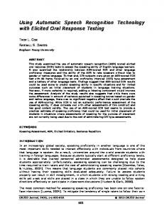
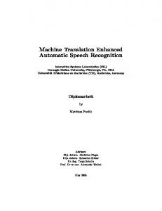
The DSP used for the implementation is a proprietary ASIC [5] whose block diagram is shown in Figure 1. It is a micro-programmed DSP, featuring an architecture similar to the one of the DSP56001 [13], with a bit-parallel MAC and separated X and Y data memories, busses and address generation units. To decrease size and power consumption, we decided to use a 16-bit architecture, instead of a 24-bit one as in the DSP56001. The different units were written using synthesizable VHDL, and interconnected, compiled and tested (before synthesis) using the program Renoir and ModelSim from Mentor Graphics [14]. Logic Synthesis was done using Design Analyzer from Synopsys [15]. FPGA rapid prototyping is done using the APEX EP20K600E from Altera [16]. A PC-based development card (Constellation 20KETM from Nova Engineering [17]) connected to the ISA bus, is used for testing. Placing and routing was done using QuartusII, from Altera, which also produces the programming files for the FPGA. The DSP contains three execution units operating in parallel: the Arithmetic Logic Unit (ALU), the Address Generation Unit (AGU) and the Controller Unit (CU). These units contain several registers, and interface over the system busses with the memories (X and Y) and the Host Interface. The parallelism of the DSP is fully exploited with instructions that keep all the units busy. At best, we can do one arithmetic operation and two data moves in parallel, plus calculation of two memory pointers, e.g.: mac x0,y1,a x:(r0)+,x0 y:(r4)−,y1 This operation executes a multiplication of the values contained in the registers X0 and Y1 and adds the result to the value contained in the accumulator A. At the same time, X0 is loaded with the value in X memory pointed by the register R0 and this pointer is post-incremented by one. Simultaneously, the register Y1 is loaded with the value in Y memory pointed by the register R4 and this pointer is post-decremented by one. 3.1.
Busses
There are three bidirectional 16-bit data busses: one for the X memory (XD), one for the Y memory (YD), and a global bus (GD), which allows transfers between the Controller Unit and the registers / memories. It also allows transfers from / to the Host Interface. A bus switch allows data transfers between the three busses. There are also two
3
XA (11 bits) YA (11 bits)
AGU_CNT
Address Generation Unit (AGU)
ALU_CNT NORM
Arithmetic Logic Unit (ALU)
MX_CNT
MY_CNT
X Memory
Y memory
XD (16 bits)
DATA BUS SWITCH (16 bits)
GD (16 bits)
PC data (8 bits) PC address (16 bits)
Control
Host Interface (HI)
Flags
PD (24)
Multimedia PC
Controller Unit (CU)
PD (24 bits)
MX_CNT MY_CNT ALU_CNT AGU_CNT
PA (10)
Data
YD (16 bits)
Program memory
Figure 1 : Block diagram of the DSP system.
independent 11-bit busses XA and YA, to address the memories X and Y respectively. 3.2.
Memory
The DSP has two independent X and Y data memory spaces. Currently, each memory space contains 2048 words of 16-bit wide, asynchronous, static memory. But the amount of memory can be easily extended with minor modifications of the VHDL code. There are also a 1024x24 bit program memory and a 64x24 bit boot memory, both internal to the Controller Unit (see Subsection 3.6). 3.3.
Arithmetic Logic Unit (ALU)
ALU operations use fractional two’s complement arithmetic. The ALU has a 16-bit input / 32-bit output multiplier and a 40-bit adder, with two 40-bit accumulators (32-bit + 8-bit extension). The multiplier output is connected to one of the adder inputs. The A and B accumulators are connected to the other input, and to the adder output to perform accumulations. Four 16-bit input registers (X0, X1, Y0, Y1) can be independently selected as input of the multiplier. Typically two of these registers can be loaded in parallel. There is also the possibility to put the same register at both inputs of the multiplier, to carry out operations such as X0*X0. Any of these registers can be loaded from the X or Y data bus. The accumulator outputs are independently connected to the X and Y data busses.
There is also a unit, between the adder output and the accumulators, which performs shifting, saturation, rounding, and normalization. The adder is capable of doing one step of a non-restoring division, which produces one bit of the quotient. No logical operations were implemented, as they are not used in the algorithm, but they could easily be implemented in the future. The ALU allows the following operations: • • • • • • 3.4.
Multiplication with and without rounding; Multiply and accumulate with and without rounding; Rounding; Division (one non-restoring division step); Normalization (one normalization step); Addition, subtraction, negation and absolute value. Address Generation Unit (AGU)
This unit performs all the storage and calculations needed for addressing data operands in memory. The AGU contains eight address registers (R0-R7), eight offset registers (N0-N7) and eight modifier registers (M0-M7). All these are 11-bit registers, allowing a maximum of 2048 words per memory space. The Rx registers contain addresses, while Nx an Mx registers are used to update or modify the Rx registers. All AGU registers can also contain generic data. The AGU has two independent arithmetic units and can thus generate two addresses per cycle. One unit is reserved for the X memory space, together with the registers R0-R3, N0-N3, and M0-M3, while the other is reserved for the Y memory space
4
together with the registers R4-R7, N4-N7, and M4-M7. Each unit can implement two types of arithmetics: linear and modulo (for circular addressing). Thus the following addressing operations are possible: • • • •
3.5.
(Rx) : indirect addressing; (Rx)+ : indirect addressing with post-increment of the address, with and without modulo; (Rx)− : indirect addressing with post-decrement of the address, with and without modulo; (Rx +/− Nx): indirect addressing with a positive or negative offset Nx, with and without modulo. Host Interface (HI)
The Host Interface unit allows data transfers between the PC and the DSP. The DSP program is also sent from the PC to the DSP (see Subsection 3.7). The data width of the development card is 8 bit, while the DSP data is 16-bit wide and the DSP program is 24-bit wide. Two or three 8bit registers are thus written by the PC, and are read as a concatenated 16-bit or 24-bit register by the DSP. Similarly, a concatenated 16-bit register is written by the DSP, and read as two 8 bit registers by the PC. Additionally, an 8-bit third register (status DSP) can be read by the PC, containing flags issued by the DSP. Other hardware flags are used to avoid either the DSP or the PC to overwrite the registers or to read invalid data. Hardware support is added to the HI, for the special instruction: WAIT, DATAPC, P:(R0)+ in order to allow program load from the PC at start-up, under control of the boot ROM (see Subsection 3.7). This instruction waits for the PC to write the 24-bit concatenated register, and then transfer this value to the program memory location pointed by the register R0 and this pointer is post-incremented by one. 3.6.
Controller Unit (CU)
The Controller Unit fetches and decodes the instructions contained in its internal program memory, and generates the different signals controlling the other blocks, which are necessary for the instruction execution. The CU also performs hardware loop control and conditional branching. Every instruction is executed in one clock cycle. The fetch and decoding of the next instruction are done during the execution of the current instruction. The assignment of the binary code to the instructions was optimally organized to minimize the amount of decoding logic, and thus the decoding time. All the instructions are 24-bit wide. The program size is currently limited to 1024 instructions, but it is easily extendable with minor modifications of the hardware. The program counter contains the address for the program memory. A program controller manages this program counter, incrementing it or loading it in case of a branch or a loop. When a conditional jump is decoded, if the tested condition is true, the destination address is loaded in the program counter. For hardware loop (DO) instruction the program controller keep track of the number of times the loop has been executed, and it exits the loop
when it has been executed the desired number of times, or return to the start address. Three registers are used to store the loop counter, the start address and the end address. These registers are stored in a hardware stack when a DO instruction is encountered, allowing nesting of DO instructions. The execution of branching and hardware loops implies no overhead other than fetching and decoding the instruction itself. 3.7.
Programming the DSP
The DSP has a 64x24 bit boot ROM, containing the program that controls the DSP at start-up. This boot program receives the actual program from the PC, putting it in the program memory. Then, it switches the control to the loaded program. A rudimentary assembler program was written using C language, in order to translate the “DSP56001 like” assembly language into DSP binary code. This program eases the programming of the DSP, allowing a higher level than using the DSP machine language. The assembler input is an ASCII file containing DSP mnemonics, and it outputs a file in MIF format which is either used by the QuartusII for initialization of the boot memory or is sent by the PC to the DSP using the DSPCOMM program (see Section 4). 4.
Development environment and methodology
An FPGA PC-based development card connected to the ISA bus (Constellation 20KETM from Nova Engineering equipped with an Altera APEX EP20K600E from Altera) is used for implementing and testing the algorithms. Loading of the FPGA programming file is done with a setup program provided by Nova Engineering. This FPGA programming file contains the definition of the DSP, including the boot program, and is kept unchanged during algorithmic development. Another PC-based program (called DSPCOMM) was written in C language, in order to send the DSP program and content of the ROM data memory to the DSP, and retrieve from the DSP the content of its data RAM, containing the results after program execution. The development environment is based on Matlab. Thus, program and data transfer between the PC and the DSP is commanded from a Matlab script, which calls the DSPCOMM program to pass the executable program and the data to be processed to the DSP and retrieve the results. These results are then compared, within Matlab, with the results produced by a bit-true C-program implementation of the algorithms running on the PC. Systematic verification is done using the whole DIGITS database. A high level simulation (Matlab program using h2m toolbox) of the training and recognition algorithms is first done to determine the optimal configuration and parameters of the system (see Section 2). As training is performed off-line, it is left as a Matlab program. Only the feature extraction and pattern classification blocks are implemented on DSP.
5
4.1.
Fixed-point quantization effects
The study of the fixed-point quantization effects was done for the feature extraction and pattern classification blocks, using the method described in [18], determining the optimum scaling and minimum wordlength needed at every node of the algorithms. The algorithms were then modified to include the scaling, and to fit their dynamic range needs into the dynamic range available in the DSP registers. The sequence of operations was then carefully optimized for implementation on the DSP. The functional blocks are coded in C language (using double-precision floating-point arithmetic) and interfaced as Matlab MEX-functions. After verification versus their Matlab version, these C-programs are used to characterize the "infinite precision" behaviour of each block and are thus the "reference system" to evaluate the degradation in performance in the case of a fixed-point implementation. Each functional block is then implemented on DSP assembly language and on C language including the DSP fixed-point arithmetic effects. This (quantized) C program is thus a "model" of the corresponding DSP implementation. Each of these C "models" is also interfaced as a Matlab MEX-function. It was verified that the DSP implementation and its corresponding C model have exactly the same output under the same input. This verification was carried out using the whole DIGITS database (11281 utterances). After that, the C model is used to measure the performance of the DSP implementation, which is 97.69 % of accuracy, slightly better than the baseline. The advantage of this approach is that the quantized C programs are easily interfaced (within Matlab) with the rest of the system. The quantized C programs can also be used to try out different implementation options before actually implementing them on the DSP. 5. 5.1.
Implementation DSP program
The program executes one cycle of the algorithm after reception of 160 samples of speech (20 ms): it calculates the acoustic features vector (see Subsection 2.2), which is then used to calculate the probability of each state of the 10 word models having output this vector, for a total of 50 probabilities (5 states * 10 word models) and then discarded. These probabilities are then used to calculate one step of the Viterbi recursion for each word model, and then discarded. Only the running value of the likelihood calculation for each word model is kept for the next frame calculation. Once the last frame is treated, the likelihood of each word model is available. The word corresponding to the model with the maximum likelihood is selected as the most likely to represent the utterance being recognized. To decrease power consumption, it is important to decrease the clock frequency (fck), as consumption is proportional to it. Power consumption is also proportional to the square of the voltage supply, which can be decreased if fck is decreased. On the other hand, for real time operation, all necessary operations to treat a frame must be
Block
Sub-block
Feature extraction
Segmentation and Preemphasis Windowing Autocorrelation Levinson-Durbin LPC → cepstrum Gaussian probabilities Viterbi Class determination
Classification
Total
Max # of cycles 659
MIPS
489 4707 1345 1050 3609
0.024 0.235 0.067 0.053
1429 87 13375
0.033
0.180 0.071 0.004 0.669
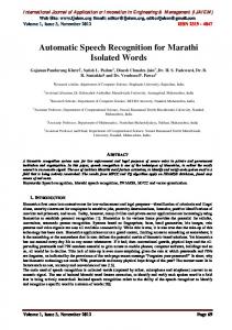
Table 1: MIPS complexity for the different functional blocks of the algorithm.
performed before the next frame is ready, that is in 20 ms. The complexity of the different functional blocks of the algorithm, measured in Million Instructions Per Second (MIPS), is given in Table 1. The total complexity of the algorithm is 0.67 MIPS. As the DSP executes one instruction per clock cycle, the minimum fck is 0.67 MHz. It is clear that the complexity of the classification is proportional to the size of the active vocabulary, whereas the complexity of the feature extraction is fixed. Thus, the total complexity is roughly given by: 0.4125 + 0.025625 *(size of the biggest active vocabulary) e.g. 0.93 MIPS in the case of a maximum size of 20 for the active vocabulary. 5.2.
Memory usage
The different fixed parameters of the algorithms which are stored in ROM, for a total size of 289 16-bit locations, are: 240 for the Hamming window coefficients, 15 for the lookup table for c0 calculation, 18 constant fractions for c1c16 calculation, and 16 for various algorithm parameters and constants. Note that at the development stage all the data are put in RAM, but the values to be integrated in ROM are already identified and grouped. The size of the temporal variables of the algorithm is 740x16 bits, but the actual size of the needed RAM is 752x16 bits due to the constraints of data alignment in order to use modulo arithmetic on the addresses. The program size is 487x24 bits. For a word model, 189 16-bit locations are needed: 14 for the transition probabilities, 85 for the Gaussian mean and 85 for the variance, and 5 for auxiliary values to decrease complexity of the probability computation. In a real dialog application, the word templates are stored in a separate FLASH memory, and the models of the active vocabulary have to be transferred to the RAM before recognition. Thus, the RAM requirement is increased by 189*(size of the biggest active vocabulary), e.g. 3780x16 bits, in the case of a maximum size of 20 for the active vocabulary. The size of the FLASH memory is given by 189*(vocabulary size). The data transfer between the DSP and the FLASH memory should be carefully designed, as it has a major contribution to power consumption.
6
6.
Future work
Future work includes the implementation of missing preprocessing functions such as end-pointing, noise reduction and adaptation, and echo cancellation for barge-in; as well as the design of the hardware support for efficient data transfer between external FLASH memory and DSP RAM. Other extension of this work is the implementation of a complete C&C dialog based on the developed recognition system. At the moment we are experimenting with the PCsimulation of a dialog to set the hour and date of a device. We would like to perform tests under real (mobile) conditions, and also compare the performance with respect to commercial engines such as Sensory Voice Activation [3], using the same set of files, recorded under real conditions. 7.
Conclusions
This paper presents ongoing work in the development and implementation of a very low complexity discrete speech recognizer, suitable for command and control in low-power miniaturized portable devices. Key points in decreasing complexity and power consumption are: the use of a proprietary 16-bit fixed point ASIC DSP, careful algorithmic optimization, fixed-point quantization effects study to keep the same performance even with the 16-bit arithmetic, and assembler implementation with optimal sequence of operations on the target architecture. This development was carried out through the contribution of student works. It was thus very interesting from the educational point of view. Furthermore, it allowed the setting up of a Matlab-based environment and methodology for efficient implementation and fast FPGA prototyping of speech processing algorithms. Acknowledgements This work was partly supported by the Swiss Federal Office for Education and Science under Grant OFES C00.0105 (COST 276 project). We are most grateful to the students who contributed to this work: M. Matthey, G. Waelchli, C. Ruettimann, M. Bellino and D. Dominé, as well as to Dr. G. Biundo who proof-read this paper. References [1] [2] [3] [4] [5]
J. Holmes and W. Holmes. Speech synthesis and recognition. Taylor & Francis, 2001. K. Frostad. The State of Embedded Speech. Speech Technology Magazine, 15 April 2003. http://www.speechtechmag.com/ http://www.sensoryinc.com/html/products/vasoftware .html http://www-3.ibm.com/software/pervasive/products/ voice/vv_mobile_device.shtml M. Matthey (Assistant: S. Grassi). VHDL implementation of a CELP speech coder (in French). Stage and diploma work, IMT-University of Neuchâtel, Switzerland and Ecole polytechnique de l'Université de Nantes (IRESTE), France. October 1999 - April 2000.
[6]
[7]
[8]
[9]
[10]
[11] [12] [13] [14] [15] [16] [17] [18]
G. Waelchli (Assistant: S. Grassi). Speech recognition for portable devices (in French). Diploma work, IMT-University of Neuchâtel, Switzerland. October 2001 - March 2002. C. Ruettimann (Assistant: S. Grassi). Isolated speech recognition for portable devices (in French). Semester project, Laboratoire de microtechnique EPFL - UNINE, Switzerland. March - June 2002. M. Bellino (Assistant: S. Grassi). Isolated speech recognition for portable devices (in French). Semester project, Laboratoire de microtechnique EPFL - UNI NE, Switzerland. October 2002 February 2003. D. Dominé (Assistant: S. Grassi). Isolated speech recognition for portable devices (in French). Semester project, IMT-University of Neuchâtel, Switzerland. March – June 2003. O. Cappé. h2m: A Set of MATLAB Functions for the EM Estimation of Hidden Markov Models with Gaussian Stateconditional Distributions. ENST, Paris. http://sig.enst.fr/~cappe/h2m/index.html http://www.elda.fr/cata/speech/S0005.html J. R. Deller, J.H. L. Hansen and J. G. Proakis. Discrete-Time Processing of Speech Signals. Macmillan, 1993. DSP56000/DSP56001 Digital Signal Processor User's Manual (DSP56000UM/AD Rev.2). Motorola Inc., 1990. http://www.mentor.com/ http://www.synopsys.com/ http://www.altera.com/ http://www.nova-eng.com/ S. Grassi. Optimized Implementation of Speech Processing Algorithms. Ph.D. Thesis, IMT-University of Neuchâtel, 1997.