IEEE EIT 2007 Proceedings
306
.
Implementation of Digital PID Controllers for DC-DC Converters using Digital Signal Processors Liping Guo Electrical & Information Engineering Technology Department of Industrial Technology University of Northern Iowa Cedar Falls, IA, 50614-0178
[email protected] Abstract— Implementation of digital PID controllers for DC-DC converters is discussed in this paper. The primary advantages of digital control over analog control are higher immunity to environmental changes such as temperature and aging of components, increased flexibility by changing the software, more advanced control techniques and reduced number of components. Analog PID and PI controllers were first designed using frequency response techniques, then converted into digital controllers. Digital PID and PI controllers are then implemented using Digital Signal Processors (DSPs). Two possible choices of DSPs are introduced. The first one is the TMS320F2812 DSP from Texas Instrument, and the second one is the Si8250 Digital Power Controller from Silicon Laboratories. Main features and development tools for both DSPs are introduced. Digital PID and PI controllers were implemented on the TI TMS320F2812 DSP. Experimental results for a prototype buck converter are presented.
I. INTRODUCTION Switch mode DC-DC converters efficiently convert an unregulated DC input voltage into a regulated DC output voltage [1]. Compared to linear power supplies, switching power supplies provide much more efficiency and power density. Switching power supplies employ solid-state devices such as transistors and diodes to operate as a switch: either completely on or completely off. Energy storage elements, including capacitors and inductors, are used for energy transfer and work as a low-pass filter. Buck converters and the boost converters are the two fundamental topologies of switch mode DC-DC converters. Most of the other topologies are either buck-derived or boost-derived converters, because their topologies are equivalent to the buck or the boost converters. Traditionally, the control methodology for DC-DC converters has been analog control. Analog-based control systems have two main advantages: low cost and a wide control bandwidth. But sophisticated control algorithms can require considerable amount of complex circuit hardware. In the recent years, technology advances in very-large-scale integration (VLSI) have made digital control of DC-DC converters with microcontrollers and digital signal processors (DSP) possible. Digital control of DC-DC converters offers several advantages over analog control [2]. First, more advanced control algorithms such as adaptive control and nonlinear control can be implemented using digital control. Second, implementation of digital control is more flexible by
c 1-4244-0941-1/07/$25.00 2007 IEEE
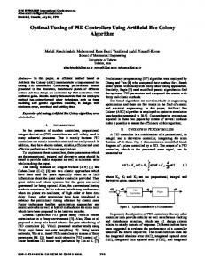
changing the software. Third, digital control can be used to achieve power efficiency optimization. In a DC-DC converter, it is desirable to maintain high efficiency over a wide range of loads. Digital control algorithms can optimize efficiency by shifting between continuous and discontinuous conduction mode with changes of load and disabling synchronous rectification at small load. Fourth, digital control is able to integrate power management functions such as thermal management into one digital control chip, thus eliminating external components. Fifth, digital control of DC-DC converters has higher immunity to environmental changes such as temperature and aging of components. Digital control for DC-DC converters can be implemented using digital signal processors (DSPs), microcontrollers and digital integrated circuits (IC). Generally, DSPs have more computational power than microcontrollers. Therefore, more advanced control algorithms can be implemented on a DSP. On the other hand, microcontrollers tend to be less expensive than DSPs, therefore providing digital control solutions at lower cost. This paper will be focused on implementation of digital controllers using DSPs. II. DESIGN OF A LINEAR PID AND PI CONTROLLERS FOR A BUCK CONVERTER In DC-DC converters, the output voltage is a function of the input line voltage, the duty cycle and the load current. It is desirable to have a constant output voltage in the event of disturbances such as a sudden change of input voltage or load current. Negative feedback control is applied to DC-DC converters to automatically adjust the duty cycle to obtain the desired output voltage with high accuracy in spite of disturbance [3]. In this section, frequency response techniques are used to design digital controller for a buck converter. A. Design of Analog PID and PI controllers The circuit diagram of a buck converter is shown in Fig. 1. The input voltage of the prototype buck converter is 20 V, and the output voltage Vo is 12 V. The load resistance R is 10 Ω, L is 150 µH and C is 1000 µF. The parasitic elements, RC and RL, are estimated to be 30 mΩ and 10 mΩ, respectively.
IEEE EIT 2007 Proceedings
307
.
iin + Vin
L
C
Gate Drive Diode
-
RL
+ R
RC
Vo -
Fig. 1 Buck converter The output-to-control small signal transfer function of a buck converter is shown in (1). It is obtained using standard state-space averaging techniques [1]. (1)
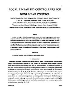
Fig. 2 Bode plot of PID controller compensated buck converter
In the transfer functions, vˆo ( s ) and dˆ ( s ) are the small variations of the output voltage and duty cycle, respectively. D is the duty cycle of the PWM signal. It is a common two-pole low pass filter, with a left half plane zero introduced by the ESR of the filter capacitance. The cutoff frequency of the low pass filter is ωc= 1 . The magnitude falls with a slope of
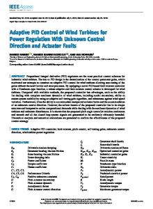
A PI controller was also designed for the control of the buck converter at steady state to reduce steady-state oscillation. One pole was placed at the origin, and one zero was placed at 800 radians/s. The DC gain of the controller was adjusted to obtain sufficient phase margin and high cross-over frequency. The transfer function of the PI controller is given by (4): 600 (4) Gc ( s ) = 0.75 + s The Bode plot for the PI compensated system is shown in Figure 3. The Bode plot shows that the phase margin is 15.4 degrees and the bandwidth is 10600 radians/s.
vˆo( s ) Vo 1 + sRCC = dˆ ( s ) D 1 + s RCC + R // RL C + L + s 2 LC R + RC [ ] R + RL R + RL
LC
–40dB/decade at the cutoff frequency. The phase associated with it is a –180 degree phase delay. The zero is at 1 . −
RC C
There is a 20 dB/decade magnitude rise at that frequency and the phase shift is 90 degrees. The control-to-output transfer function at the nominal operating point is given by (2). The model has complex conjugate poles at –615.9 ± j2481.5, which causes a 180 degrees phase delay at the approximate frequency of 2500 radians/s. The model also has a zero at 33,333 radians/s.
vˆo ( s ) 6 × 10⁻⁴ s + 20 = −7 2 −5 dˆ ( s ) 1.503 × 10 s + 5.4975 × 10 s + 1
(2)
A PID controller was designed for the buck converter to improve the loop gain, cross-over frequency and phase margin. One zero was placed an octave below the cutoff frequency (approximately 260 radians/s) and the other one at 4600 radians/s. The transfer function of the PID controller is given by (3): 142 .4 (3) Gc (s ) = 0.5786 + + 0.000119 s s The Bode plot for the compensated system is shown in Figure 2. As can be seen in this plot, the gain at low frequency is high, the phase margin is 107 degrees and the bandwidth is 19100 radians/s.
Fig. 3 Bode plot of PI controller compensated buck converter B. Transformation from Analog Controllers into Digital Controllers An analog PID controller’s transfer function is shown in (5), and is implemented using (6), where KP, KI and KD are determined when the controller is designed. K (5) GC ( s) = K P + I + K D s s K de(t ) (6) GC (t ) = K P e(t ) + K I ∫ e(t ) dt + D dt
IEEE EIT 2007 Proceedings
308
.
A digital PID controller also satisfies (6), except the multiplication, integration and differentiation are performed numerically in a digital computer [4]. If the numerical calculations are performed accurately, the system response using digital control will be very similar to the system response using analog control. Several methods can be used to obtain the discrete-time equivalent of an analog PID controller. These methods are backward difference method, forward difference methods, bilinear transformation method, impulse-invariance method, step-invariance method and matched pole-zero method [5]. The backward difference method is one of the simplest methods to obtain numerical integration of a signal. It will produce a stable discrete-time filter for a stable continuoustime filter. Using the backward difference method, the transfer function of a numerical integrator is shown in (7). M ( z) =
Tz E(z) z −1
(7)
K I Tz K D ( z − 1) + z −1 Tz
(8)
The transfer function of a numerical differentiator is the reciprocal of the transfer function of the numerical integrator shown in (7). Therefore, by substituting (7) and its reciprocal into the PID controller’s s-domain transfer function in (5), the digital PID controller’s transfer function is shown in (8). GC ( z ) = K P +
A digital PI controller’s transfer function is shown in (9) by eliminating the derivative term in (8). K Tz (9) GC ( z) = K P + I z −1 The difference equation to calculate a new duty cycle for the digital PID controller is written in (10). k K u[ k ] = K P e[ k ] + K I T ∑ e[i ] + D {e[ k ] − e[ k − 1]} (10) T i =0 In the difference equation, u[k] is the controller output for the kth sample, and e[k] is the error of the kth sample. The error e[k] is calculated as e[k] = Ref-ADC[k], where ADC[k] is the converted digital value of the kth sample of the output voltage, and Ref is the digital value corresponding to the desired output voltage.
k
∑ e[i]
is the sum of the errors and {e[k]-e[k-1]} is
i =0
the difference between the error of the kth sample and the error of the (k-1)th sample. It is noted that when KD is equal to zero, the PID algorithm changes into a PI algorithm. III. IMPLEMENTATION OF DIGITAL PID AND PI CONTROLLERS This paper will mainly concentrate on implementation of digital PID and PI controllers using Digital Signal Processors (DSP). The first DSP discussed is a TMS320F2812 DSP from Texas Instrument. The second DSP discussed is a Si825x Digital Power Controller from Silicon Laboratories. A. TMS320F2812 Digital Signal Processor The TMS320 family of digital signal processors (DSP), produced by Texas Instruments, is composed of fixed point, floating point and multiprocessor DSPs. The TMS320 family
has three DSP platforms: the TMS320C6000TM DSP, the TMS320C5000TM DSP, and the TMS320C2000TM DSP. The TMS320C2000TM DSP platform is optimized for control applications. The TMS320F2812 DSP belongs to the TMS320C28x generation, which is the newest member of the TMS320C2000TM DSP platform. By integrating the DSP core and on-chip peripherals, the TMS320C28x DSP generation offers a high-performance solution to digital control. It targets a wide variety of digital control applications including industrial control, motor control and automobile control applications. The TMS320F2812 is a 32-bit fixed point DSP controller with on-board flash memory [6]. The CPU operates at 150 MHz. The C28x DSP generation is efficient in executing C and C++ programs, hence enabling control algorithms to be developed in high level languages. The CPU features 16×16 and 32×32 MAC operations, 16×16 dual MAC, Harvard bus architecture, atomic operations, fast interrupt response processing, unified memory programming model and up to 4M linear program/data address reach. The on-chip memory includes up to 128K flash memory, up to 128K ROM devices, and a combined 18K SARAM devices. Development tools include ANSI C/C++ compiler/assembler/linker and Code Composer Studio (CCS) IDE. The TMS320C2000 Code Composer Studio is a Windows-based integrated development environment (IDE). The CCS IDE includes software tools for project managing and editing, code generation, debugging, code optimization, real time kernel and analysis. The F2812 supports peripherals used for embedded control and communication, such as an event manager module for pulse-width-modulation (PWM) and a dual 12-bit, 16-channel analog-to-digital converter (ADC). Serial port peripherals include serial peripheral interface (SPI), two serial communication interfaces (SCIs), enhanced controller area network (Ecan) and multichannel buffered serial port (McBSP). The peripheral interrupt expansion (PIE) block supports 45 peripheral interrupts [7]. . The TMS320F2812 DSP controller comes in a 176 pin package. The pins can be categorized according to functions: address and data bus, interface control signals, ADC inputs, bit I/O and shared functions bits, serial communication interface, compare signals, interrupts signals, clock signals and test signals. The overall program structure is shown in Figure 4. Once the program starts to run, the first task is to initialize the DSP. Macros such as clearing bit, setting bit and setting a certain amount of delay time are defined. The interrupt vector addresses map the subroutines corresponding to each level of interrupts. The global variables are declared and given initial values. The event manager module is initialized to define the sampling and switching frequency, which is determined by the period of the general purpose timers. Then certain bits are set to start the PWM. The analog to digital conversion is set to be in the continuous conversion mode. After the configuration of the DSP is complete, the main algorithm starts to run. Each time when the value of the general purpose timer is equal to the timer’s period value, an interrupt is requested and directed to the corresponding interrupt subroutine. The sampling period is equal to the period of the general purpose timer.
IEEE EIT 2007 Proceedings
309
.
The interrupt subroutine is executed every sampling period. The subroutine acquires a sample once every sampling period, utilizes a digital controller algorithm to calculate a new duty cycle, and updates the new duty cycle at the start of the next switching period. Different digital control algorithms, including PID and PI controllers and fuzzy logic controllers can be implemented as interrupt subroutines. The flowchart for the digital PID and PI controller is shown in Figure 5. At the start of each sampling period, there was a 2µs delay before taking the analog to digital conversion. Because the sampling and PWM switching frequency were the same and their periods were synchronous, the start of the sampling and switching periods happened at the same time. The switching action of the MOSFET in the DC-DC converter produces a glitch in the converter output voltage which can be measured by the A/D converter. Measurement of this glitch will produce oscillation in the duty cycle calculated by the digital PID controller. The sample was taken after the start of the switching period instead to avoid sampling the switching glitches. When both the absolute value of the error of the kth sample e[k] was less than ε, and the absolute value of the difference between the error of the kth sample and the error of the (k-1)th sample de[k] was less than φ, the converter was considered to be operating in steady state. The values ε and φ can be determined based on experimental results of the converters. The PI controller was applied in steady state to reduce oscillation of the duty cycle. The gain of the integrator KD was assigned to be zero, and the proportional and integral gains KP and KI were assigned according to the design of the PI controller. The result of the PID controller was a sum of the proportional, derivative and integral controllers. The duty cycle of the PWM signal in the digital control system for the buck converter was limited between 10% and 90%. This prevents the MOSFET from being turned on or off for a full switching period. After updating the new duty cycle, and the error of the (k-1)th sample, the interrupt subroutine returned to the main program and waited for a request for the next interrupt. The difference equation in (10) is a linear combination of feedback and control signals. A series of scalar multiplications and addition instructions can be used to implement the linear PID and PI controllers on the TMS320F2812 DSP. The TI TMS320F2812 DSP is optimized for implementation of digital filters. It has several instructions to multiply a number by a constant and add the previous product in a single instruction. Therefore, the implementation of linear PID and PI controllers in real time is quite straightforward.
Fig. 4 Overview of the program structure for digital controllers on a TMS320F2812 DSP Because of the strong computation power of the TMS320F2812 DSP, more advanced control algorithms such as fuzzy logic control and adaptive control can be implemented on the DSP [8]. B. Si8250 Digital Power Controller The Si825x family of programmable digital power controllers from Silicon Laboratories provides closed-loop feedback control, system protection and power management functions for switch mode power supplies. The Si825x architecture combines a dedicated DSP-based control loop processor with a microcontroller-based programmable system management processor. This architecture guarantees the
IEEE EIT 2007 Proceedings
310
. Interrupt Subroutine Starts
Delay 2 us ADC Conversion Complete e[k]=Ref-ADC[k] de[k]=e[k]-e[k-1] No
e[k ] ≤ ε ?
No
de[ k ] ≤ φ ?
Yes
Yes Assign values for PID controller gains KP, KI and KD
Assign values for PI controller gains Kp, Ki. KD=0
Fig. 6 Compensator Editor P=KP*e[k] k
k −1
i= 0
i =0
∑ e(i ) = ∑ e (i) + e (k ) k
I = K I T ∑ e(i) i=0
D=KD /T*de[k] PID=K+I+P Yes
PID>90%? No
PID=90%
PID