Implementation Options for the Distribution System in the 802.11 Wireless LAN Infrastructure Network Amre El-Hoiydi CSEM - Centre Suisse d’Electronique et de Microtechnique Rue Jaquet-Droz 1, 2007 Neuchâtel, Switzerland
[email protected]
The ad hoc network mode is meant to easily interconnect laptops that are in the same area, for example in a meeting room. No access to a wired LAN is foreseen. The interconnected stations in ad hoc mode are forming an independent basic service set (IBSS). The following sections will first discuss the mobility management in 802.11, describe the logical components constituting an infrastructure network, and then present and compare different options to implement the distribution Keywords - 802.11, wireless local area network, WLAN, mobility system. Finally, the implementation of an infrastructure network using stations in ad hoc mode as MAC bridges or IP management, roaming, inter-access point protocol, IAPP. gateways will be discussed. A list of acronyms is given in section VI. I. INTRODUCTION Abstract - The IEEE 802.11 wireless LAN standard specifies which messages shall be exchanged between an access point and a station to support mobility. However, the implementation of mobility in the wired part of the network, i.e. the distribution system or inter-access point protocol, is not specified. This paper presents and evaluates different options for the implementation of the distribution system used to forward messages between stations in a wireless LAN infrastructure network. The usage of stations in ad hoc mode as bridges or gateways towards a wired LAN is also discussed.
Because the distribution system implementation has not been defined in the 802.11 standard, access points from different vendors are unlikely to inter-operate. The IEEE 802.11 group is thinking about defining such a protocol [1]. H. Moelard and M. Trompower have earlier written a proposal for an inter-access point protocol in the form of an internet draft standard [2]. This protocol is implemented on top of UDP/IP and is using the IP multicast function to link all access points together. The messages containing the routing information are meant to be multicast periodically. In the literature, the only article discussing the distribution system that could be found is [3], which proposes a mobility management protocol inspired from cellular networks protocols. In this scheme, every station must be associated with a home access point, which keeps track of the location of a roaming station. A station wanting to send a frame to another station must ask the home access point of the destination station about the roaming access point identity. No method is however given to find out which is the home access point of a given station. In cellular networks, the phone number gives this information. The cellular network location management doesn't seem to be a good starting point for wireless LAN packet networks. The wireless LAN standard IEEE 802.11 defines two basic modes of operation: the infrastructure network and the ad hoc network ([4], [5], see Fig. 1). The infrastructure network is meant to extend the range of the wired LAN to wireless cells. A laptop can move from cell to cell while keeping access to the resources on the wired LAN. A cell is the area covered by an access point and is called a basic service set (BSS). The collection of all cells of an infrastructure network is called an extended service set (ESS).
II.
MOBILITY MANAGEMENT IN AN INFRASTRUCTURE NETWORK
In a packet radio network, the goal of the mobility management is to route the incoming packets towards mobile nodes. The mobility management is composed of the location management procedures to keep track of mobile nodes, and of either the handover of a connection or the forwarding of packets. In a connection oriented packet network such as wireless ATM, the ATM virtual connection is redirected (handed over) to the new location of the mobile node [6]. In Internet Gateway Ethernet (or something else)
Access Point
Access Point
Access Point
ESS Infrastructure Network
Ad Hoc Network
BSS
IBSS
Fig. 1. 802.11 infrastructure or ad hoc network
a connectionless packet network such as 802.11 or mobile IP, each packet is routed individually through the mobile network infrastructure towards the mobile node. The nodes of the wireless infrastructure network will route packets targeted to a mobile node into the correct cell by looking up routing tables. These tables are maintained by location management procedures. In the 802.11 system, the location management procedures include the association messages and the messages exchanged between access points and portals, as explained below.
Internet Desktop Comp Gateway
Ethernet
Portal
DSS AP1
distrib assoc
SS
SS STA1
DSS AP2
distrib assoc
SS
SS STA2
distrib
DSS
assoc
AP3
SS
SS STA3
Fig. 2. Infrastructure network - logical services
the distribution system medium and a wired LAN. In an access point, the DSS is composed of the association and distribution services. In a portal, the DSS is composed of the distribution and integration services. OPERATION
Before to go into the distribution system implementation details, the operation scenario of a moving station in a 802.11 infrastructure network is briefly presented: A. Scanning: When a station powers up inside the coverage area of an access point, it listens for a beacon frame containing the identity (SSID) of the wireless network that the station wishes to join. B. Association: The station sends an association request to the access point, informing the access point of its presence and of its MAC address. C. Traffic: The station 1 in Fig. 2 sends a message to station 3 through the access point 1 using the frame format shown in Fig. 3 (top). This message is received by access point 1, which looks into its table to find out by which access point the station 3 is covered, and then forwards the message to access point 3. The access point 3 sends the message to the station 3 using the format shown Fig. 3 (bottom). If the station 3 were in the same BSS as station 1, the scheme would be identical. The message would be received by the access point and forwarded to the station 3. The input and output access points would be identical.
Data frame from the station to the access point (In the FrameControl: ToDS bit is 1, FromDS bit is 0): Frame Address 1 Control BSSID (=MAC AP 1)
Address 2 SA = MAC Station 1
Address 3 Sequ DA = MAC Station 3 Control
Address 4 Not Used
Frame Body 0-2312 octets
FCS
Frame Body 0-2312 octets
FCS
Data frame from the access point to the station (In the FrameControl: ToDS bit is 0, FromDS bit is 1): Frame Address 1 Address 2 Control DA = MAC Station 3 BSSID (=MAC AP 3)
Address 3 SA = MAC Station 1
distrib
Distribution System Medium
LOGICAL SERVICES
The access points are interconnected by a wired (or wireless) distribution system. The distribution system is then connected to a wired LAN through a portal. There are three types of nodes: the station (a laptop), the access point which connects a wireless cell to the distribution system, and the portal which connects the distribution system to a wired LAN (see Fig. 2). All traffic is exchanged through the access points. A common choice to implement the distribution system is to use Ethernet, but any other medium is also allowed. The different functions constituting the 802.11 functionality are split into the station service (SS) and the distribution system service (DSS). A station has the SS. An access point has the SS and the DSS. A portal has the DSS. The station service is mainly responsible for the delivery of MAC service data units (MDSU), i.e. sending and receiving messages through the air interface using the 802.11 MAC protocol. The other tasks of the station service are optional: the authentication between stations using a shared secret key and the ciphering of the transmitted data. The distribution system is formed by a distribution system medium (DSM) and a distribution system service function in each access point and portal. The 802.11 standard does not specify how the distribution system will transfer a message from the source access point or portal to the destination access point or portal. It only specifies the association protocol, which will give to the distribution system enough information to perform its task. To summarize, the association service is used by a station to let the access point know that it is responsible for forwarding the message to it. The distribution service is used by an access point or portal to forward a data message to the correct access point or portal through the distribution system medium. The integration service is used by a portal to inter-work between
integr
DSS
Sequ Control
Address 4 Not Used
Fig. 3. MPDU - Data frame to/from the distribution system
LLC 802.2
LLC 802.2 assoc distrib
MAC 802.11 MAC 802.11 station
assoc distrib
LLC 802.2
LLC 802.2
MAC 802.3
MAC 802.3
access point
MAC 802.11 MAC 802.11
access point
station
LLC 802.2 distribution system medium
distrib integr LLC 802.2
The problem can be divided into two parts. The first is to choose how to transport the data across the distribution medium. The second is to choose a signaling protocol between access points and the portal to keep the local routing tables up-to-date.
MAC 802.3 MAC 802.3
MAC 802.3
wired LAN portal
desktop computer
Fig. 4. Option 1 - Protocol stack of the DSM implementation using MAC layer addressing and separated DSM and wired LAN
D. Mobility: When station 1 moves from BSS1 to BSS2, it sends a reassociation message which contains its MAC address and the identity of the old access point. E. Disassociation: When leaving the network (e.g. when shutting down), the station should send a disassociation message to the access point. This message shall not be mandatory for the system to work. WHY FORWARDING MESSAGES WITHIN A BSS ?
It may be questioned why a message sent by station 1 in BSS1 to station 2 in BSS1 must go through the access point, as this consume two times the bandwidth that is really needed. The main reason is that the mobility support across BSSs is wanted to be transparent to the logical link control layer (LLC, see §5.2.2.1 of [4]). The interconnected BSSs (forming an ESS, see Fig. 1) look like a single Ethernet cable to the LLC layer. The sending station cannot know whether the receiving station is within the same BSS or not. The destination address (address 1 field in the MAC frame) is therefore always the address of the access point, and the address field 3 contains the address of the ultimate destination station. The access point is responsible of forwarding the packet in any BSS. Defining a BSS as the access point plus all stations in visibility of the access point also nicely solves the problem of the hidden node. All stations can hear the access point and hence the RequestToSend or the ClearToSend messages sent by the access point. The standard could have been different, with a kind of MAC level "proximity discovery protocol" that would permit to know whether a destination station is close enough to directly receive a message, but this would have added complexity and brought back the hidden node problem. III. IMPLEMENTATION OF THE DISTRIBUTION SYSTEM Four possibilities to implement the distribution system are presented in the following sections. Three of them use IEEE 802 MAC level addressing and the other one uses network layer addressing.
OPTION 1: MAC LAYER ADDRESSING - SEPARATED DSM AND WIRED LAN
Transport: The most obvious choice is to select Ethernet to implement the DSM as shown in Fig. 4. Different Ethernet cables can be connected with repeaters or bridges to form the DSM. The main thing is that the DSM is a broadcast medium, where every access point and portal can receive every message. To begin with, lets recall the MAC service data unit (MSDU) and MAC protocol data unit (MPDU) definitions: The MSDU is the data block exchanged by the MAC with the higher layers. The MPDU is the MAC frame sent over the air. A MSDU may be fragmented into several MPDUs mainly to reduce the frame error rate over the air. This type of fragmentation does not impact the routing and will not be considered further. Each access point maintains a table containing a mapping of the station 802.11 MAC address to the access point Ethernet MAC address. According to the situation is Fig. 2, the table in the access points would be identical to the one in Table I. For a message transfer between station 1 and station 3, access point 1 will transmit to access point 3 the original MSDU. As the maximum size of a MSDU in 802.11 (2304 bytes [4]) is larger than the maximum size of the payload of an 802.3 frames (1492 bytes when a SNAP header is used [7]), it will be necessary to fragment it into two Ethernet messages. Note that in this paper, we consider only the IEEE 802.3 Ethernet and not the older Ethernet standard from Xerox/Intel/Digital. In order to enable the receiving node to reassemble the two corresponding segments without mixing segments from different sources, a connection protocol is needed. A twoway signaling exchange could build a unique connection identifier out of two local identifiers, but this would introduce an unacceptable delay. A better solution would be to generate a random connection number at the source, so that it will be unlikely that two identical connection numbers from two different sources will be mixed at the receiver. The alternative is to limit the size of the MSDU to 1476 in the 802.11 network, so that the MSDU plus possibly 8 bytes for the WEP encryption, plus the MAC address of the source and destination stations of 4 bytes each will fit into the 1492 bytes of the 802.3 payload. In any case, such a limitation will TABLE I MAC LAYER ROUTING TABLE Destination MAC address 802.11 MAC Addr. STA1 802.11 MAC Addr. STA2 802.11 MAC Addr. STA3 Eth. MAC Addr. Desktop Comp.
o o o o
Next Node Ethernet MAC Addr. AP1 Ethernet MAC Addr. AP1 Ethernet MAC Addr. AP3 Ethernet MAC Addr Portal
be needed if bridging between the wireless LAN and a 802.3 LAN is wanted (see [8] § 6.3.8). Once the access point 3 has successfully received the MSDU trough the distribution system medium, it constructs an MPDU with address fields as shown in Fig. 3 and transmits it over the air to station 3. Signaling: The role of the location management signaling is that each node knows through which access point or portal a given MAC address can be reached. The association message that is sent by the stations when entering a BSS allows an access point to maintain a list of MAC addresses in its BSS. It needs to get information for the other MAC addresses. This problem of finding out which access point corresponds to which MAC address is very similar to the problem solved by ARP [9]. In ARP, it has been chosen to dynamically learn about relevant addresses, instead of periodically broadcasting long lists. This makes sense in our case as well. It is proposed that the access point will dynamically build a minimal routing table by broadcasting a routingRequest message to all access points and to the portal, every time a destination MAC address is not found in its routing table. If the MAC address corresponds to a station in another BSS, the associated access point will know it and will send a routingReply. The other access points may also add this entry in their routing table when hearing this message. If the destination MAC address belongs to a computer on the wired LAN, the portal may know it and send a routingReply. If the portal does not know it, no reply will be sent. After a time-out, the requesting access point will send it directly to the portal, assuming that this MAC address is on the wired LAN. When a station moves from one BSS to another, an routingNotification message must be sent by the access point, giving to the other access points the opportunity to update their routing tables. A routingConfirmation message will have to be sent back by the old access point. This confirmation is needed to be sure that this old access point will reroute data messages to the new access point, in case another access point did not catch the routingNotification message. If this old access point receives such a data message to reroute, it will send a routingNotification message to the mistaken source access point or portal to correct the situation.
software, which forwards it inside the 802.11 BSS, including the LLC header. Having the portal function in all access point prevents the need of sending over the DSM all frames sent from the wired LAN towards the ESS, as it would the case with only one portal, This reduces the total traffic on the wired LAN. The signaling protocol between access points remains as in option 1. OPTION 3: MAC LAYER ADDRESSING - MAC BRIDGE
If it is acceptable to reduce the size of an MSDU in the 802.11 network to 1476, a very simple solution to implement the distribution system exists: Each access point is a filtering bridge between the BSS and the wired Ethernet LAN. No location management signaling is even needed. The filtering feature is very important in order to prevent that a BSS becomes overloaded with traffic that is not targeted to stations in this BSS. The filtering table is maintained using the association messages. A message sent by a wireless station targeted to a computer (desktop or wireless station) outside of the BSS will be bridged to Ethernet. If a filtering access point recognizes the destination MAC address as being in its BSS, it will bridge it into the 802.11 cell. OPTION 4: NETWORK LAYER ADDRESSING
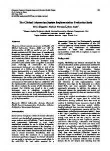
Having all access points connected to the same medium limits the flexibility in the deployment of the access points. It is possible to use a network layer addressing within the DSM using the stacks shown in Fig. 6. This will permit to run the location management and forwarding protocols presented in option 1 over an IP network composed of various LANs interconnected by routers. The main difference in the implementation of the distribution system with the option 1 is that the DSM is not a broadcast medium anymore. A routing signaling message from one access point or portal cannot be simply broadcast to all other access points and to the portal. Such a message must be multicast, and the IP address of all access points and portal belonging to the same radio network must be known to each access point and portal or to a central entity. A supplementary protocol is hence necessary to make this possible. For example, the portal could be defined as a
OPTION 2: MAC LAYER ADDRESSING - COMBINED DSM AND WIRED LAN
It can be chosen to insert the portal function in each access point, as shown in Fig. 5. This implies that the distribution system uses the same physical network as the wired LAN. In this case, even if the integration function is a non-filtering bridge, it should not forward every received 802.3 MAC frame to the whole ESS, but should only forward 802.3 MAC frames that do not contain distribution system data and forward them only into its own BSS, or an avalanche of traffic will happen. The distribution system traffic can be recognized by a value in the LLC header, specifying a private protocol. If a message is recognized to be a distribution system message, the Ethernet driver strips the LLC and DS header away and gives the message to the distribution software layer. If the LLC header announces something else, then the Ethernet driver gives it up to the integration
LLC 802.2
LLC 802.2 assoc
MAC 802.11
integr distrib
MAC 802.11
assoc MAC 802.11
distrib
LLC
LLC
MAC 802.3 station
integr
MAC 802.11
MAC 802.3 access point / portal
access point / portal
station
LLC 802.2 wired LAN and distribution system medium
MAC 802.3
desktop computer
Fig. 5. Option 2 - Protocol stack of the DSM implementation using MAC layer addressing and combined DSM and wired LAN
server to which every access point must announce itself. Each access point will inform the server of the MAC address of the stations in its BSS using routingNotification messages. When an access point cannot find a MAC address in its routing table, it sends a routingRequest to the server. If this MAC address is in one of the BSSs, the server will know it and send a routingReply message indicating the associated access point. If the MAC address is not the one of a known station, it is supposed to be on the wired LAN and the routingReply contains the identity of the portal. When a station has moved into another BSS, the access point responsible of the new BSS must inform all other access points of the change. This can be done by sending the routingNotification message to the server, which then multicast it to all access points. With this mechanism, only the server must know the list of IP address of all access points. This solution is inspired from what is used for ARP in IP over ATM [10], which is also a non-broadcast medium. The routing table in each access point is similar as the ones in the option 1 and is shown in Table II. As the maximum size of an IP packet is 65 kbytes, it will be possible to carry MSDU of the maximum size without segmentation. An interesting application of such an IP layer distribution system would be to setup a virtual private network, with cells distributed in different buildings interconnected by the internet. All these cells will appear to be in the same subnet, and the same resources (email, file and application server, firewall) will be available in all cells. In this case, where the access points are in different subnets, it is desirable to install only one portal. Having the portal functionality in each access point would mix the broadcast traffic of every different subnet into the wireless ESS. In such an infrastructure network, the exchange of IP traffic between a desktop computer and a station would follow the scenario presented hereafter: We assume that all stations and the desktop computer are in the same IP subnet, connected through the internet. In this scenario, the desktop computer sends IP packets to a laptop, which is moving from BSS1 to BSS2. The server function is LLC 802.2
LLC 802.2 assoc distrib
MAC 802.11 MAC 802.11 station
assoc distrib UDP/IP
LLC 802.2
LLC 802.2
MAC 802.3
MAC 802.3
access point
subnet 192.168.120.0
subnet 192.168.122.0
station subnet 172.16.100.0
subnet 192.168.121.0
distribution system medium IP Router
MAC 802.11
access point
IP Router
subnet 172.16.100.0
MAC 802.11
UDP/IP
LLC 802.2
distrib integr
MAC 802.3
UDP/IP LLC 802.2
MAC 802.3
MAC 802.3
portal
wired LAN desktop computer subnet 172.16.100.0
Fig. 6. Option 4 - Protocol stack of the DSM implementation using network layer addressing
TABLE II NETWORK LAYER ROUTING TABLE Destination MAC address 802.11 MAC Addr. STA1 802.11 MAC Addr. STA2 802.11 MAC Addr. STA3 Eth. MAC Addr. Desktop Computer
o o o o
Next Node IP Addr. AP1 IP Addr. AP1 IP Addr. AP3 IP Addr Portal
in the portal. When the desktop computer wants to send a first IP packet to the laptop, it looks for the corresponding MAC address by broadcasting the question "Who has the IP address 10.140.150.51" (ARP Request). As this ARP request is a broadcast message, it is forward by the portal to every access point, which send it into their respective BSS. The laptop will hear it in BSS1 and send the ARP reply through the access point 1 with the destination MAC address of the desktop computer. The access point 1 will send a routingRequest message to the portal asking which access point can reach the given MAC address. As the destination MAC address on the wired network, the portal replies with a routingNotification to forward the messages to itself. The access point 1 forward the ARP reply to the portal which forward it further on the wired LAN. The desktop computer will then send every message targeted to the laptop on the wired LAN using the 802.11 MAC address of the laptop as the destination address. As the portal knows that this MAC address is in its wireless network, it will fetch the messages and forward them to access point 1. When the laptop moves into another BSS, the new access point will inform the portal and the other access points of the change using a routingNotification message to the portal. IV. INFRASTRUCTURE AD HOC NETWORK In an ad hoc network, every station can communicate with every other station by sending MAC frames as shown in Fig. 7. The only involved service is the station service, which is constituted by the MSDU delivery, the optional peer authentication and the optional ciphering of the data. Although not specified by the 802.11 standard, it is possible to setup a station having an Ethernet and a 802.11 interface as an access point connecting the IBSS to the wired infrastructure. The reason to use a station in ad hoc mode as the access point, instead of a true access point running the association protocol is mainly because of the availability of public domain source code for the station drivers and not for the access point drivers. For example, any 802.11 card driver for Linux supporting the ad hoc mode can be used [11]. Such ad hoc access point are meant to be used for laboratory protocol testing rather than to setup real life wireless networks, mainly because no mechanism for the frequency reuse is available. Each cell must use the same frequency. The different options to configure such a station are for example:
Frame Duration/ Control ID
Address 1 DA = MAC Station 3
Address 2 SA = MAC Station 1
Address 3 BSSID
Sequ Control
Address 4 Not Used
Frame Body 0-2312 octets
FCS
Fig. 7. MPDU between stations in an ad hoc network (in the FrameControl: ToDS bit =0, FromDS bit =0)
Ad Hoc MAC Bridge: If the station bridges the traffic between its Ethernet and 802.11 interfaces, it will be like an access point with the following limitations: As there is no distribution system, the maximum size of the MSDU must fit into the payload of an Ethernet frame. Because there is no master to choose a frequency to be used by every one, a predefined frequency must be used. Adjacent cells using the same frequency will create closed bridging loops. Note that such bridging to and IBSS is explicitly forbidden by the MAC Bridge standard [8] in § 6.5.6. Ad Hoc IP Forwarder: Configuring the stations as an IP forwarder offers the advantage using the IP layer of an operating system with all associated networking functions (network address translation, firewall). The problem with IP forwarding is that both network interfaces must be in different subnets. Hence, the mobile node must know the IP address of the 802.11 interface of the ad hoc IP forwarder and configure its operating system to use it as the default gateway. Proxy ARP or NAT/DHCP: To be freed of the hassle of setting the new default gateway in the mobile laptop in each new cell, the IP forwarder could be replaced by a proxy ARP server making the wireless station appear as a station on the wired Ethernet. Alternatively, a network address translation (NAT) function coupled with a DHCP server can be used. However, a disadvantage of all IP based solutions (IP forwarding, Proxy ARP, NAT/DHCP) is that other network layer protocols like AppleTalk or NetBUI are not supported. V. CONCLUSION Different solutions have been presented to implement the fixed part of a 802.11 wireless network. Using an Ethernet backbone, the best solution to implement the distribution system appears to be using MAC layer addressing and combined access points and portals (option 2). If the maximum size of the MSDU in 802.11 is reduced to 1476 bytes, the implementation of this scheme is reduced to a filtering MAC bridge function. On the other hand, the usage of network layer addressing offers much more flexibility for the architecture of the backbone network. This flexibility will become needed when setting up large wireless local area networks. Therefore, the option 4 is clearly seen as a better a more future proof solution. Compared to the IAPP protocol proposed in [2], the one presented in option 4 has the advantage of not needing to use the IP multicast function and of reducing the signalling traffic by not periodically multicasting the routing information.
VI. ACRONYMS AP APP ARP BSS BSSID DHCP DSM DSS ESS IBSS IP LAN LLC MAC MPDU MSDU PCF SS SSID STA UDP
Access Point combined Access Point and Portal Address Resolution Protocol Basic Service Set Basic Service Set Identity Dynamic Host Configuration Protocol Distribution System Medium Distribution System Service Extended Service Set Independent Service Set Internet Protocol Local Area Network Logical Link Control Media Access Control MAC Protocol Data Unit MAC Service Data Unit Point Coordination Function Station Service Service Set Identifier Station User Datagram Protocol
REFERENCES [1]
IEEE 802.11, IAPP Project Authorization Request, "Recommended Practices for Multi-Vendor Access Point Interoperability via InterAccess Point Protocol across Distribution Systems supporting IEEE P802.11 operation", November 1999. http://www.ieee802.org/11/PARs/9275-r1-8W-PAR-and-5-CriteriaIAPP.pdf [2] Henri Moelard, Michael Trompower, "Inter Access Point Protocol", Internet Draft Standard, March 1998. [3] W.K. Kuo, C.Y. Chan, K.C. Chen, "Time Bounded Services and Mobility Management in IEEE 802.11 Wireless LANs", IEEE International Conference on Personal Wireless Communications 1997- ICPWC'97, Mumbai (Bombay), India, p. 157-161. [4] IEEE P802.11/D10, Draft Standard, “Wireless LAN Medium Access Control and Physical Layer Specifications,” 14 January 1999. [5] IEEE 802.11 "Wireless Local Area Networks", IEEE Communications Magazine, September 1997, p. 116-126. [6] Ender Ayanoglu, et al, "Mobile Information Infrastructure", Bell Labs Technical Journal, Autumn 1996, http://www.lucent.com/ ideas/perspectives/bltj [7] J. Postel, J. Reynolds, RFC-1042, "A Standard for the Transmission of IP Datagrams over IEEE 802 Networks", February 1998. [8] IEEE Std 802.1D, 1998 Edition, "Media Access Control (MAC) Bridges". [9] D. C. Plummer, RFC-826, "An Ethernet Address Resolution Protocol", November 1982. [10] M. Laubach, J. Halpern, RFC-2225, "Classical IP and ARP over ATM", April 1998. [11] Jean Tourrilhes, "The devices, the drivers. The who's who of Wireless LANs under Linux", 6 March 2000, http://www.hpl.hp.com/ personal/Jean_Tourrilhes/Linux/Linux.Wireless.drivers.html