Dec 28, 2004 - lengedâ environments, the deployment of DTN systems can result in .... ital Courier [17] project in South Africa transfers e-mail messages and Web searches ..... valuable for rapid prototyping and automated testing. Application ...
Implementing Delay Tolerant Networking
(IRB-TR-04-020, Dec.28 2004 , Michael Demmer, Eric Brewer, Kevin Fall, Sushant Jain, Melissa Ho, Robin Patra) INFORMATION IN THIS DOCUMENT IS PROVIDED IN CONNECTION WITH INTEL® PRODUCTS. NO LICENSE, EXPRESS OR IMPLIED, BY ESTOPPEL OR OTHERWISE, TO ANY INTELLECTUAL PROPERTY RIGHTS IS GRANTED BY THIS DOCUMENT. EXCEPT AS PROVIDED IN INTEL'S TERMS AND CONDITIONS OF SALE FOR SUCH PRODUCTS, INTEL ASSUMES NO LIABILITY WHATSOEVER, AND INTEL DISCLAIMS ANY EXPRESS OR IMPLIED WARRANTY, RELATING TO SALE AND/OR USE OF INTEL PRODUCTS INCLUDING LIABILITY OR WARRANTIES RELATING TO FITNESS FOR A PARTICULAR PURPOSE, MERCHANTABILITY, OR INFRINGEMENT OF ANY PATENT, COPYRIGHT OR OTHER INTELLECTUAL PROPERTY RIGHT. Intel products are not intended for use in medical, life saving, life sustaining applications. Intel may make changes to specifications and product descriptions at any time, without notice. Copyright © Intel Corporation 2003 * Other names and brands may be claimed as the property of others.
1
Implementing Delay Tolerant Networking Michael Demmer∗† , Eric Brewer† , Kevin Fall∗ , Sushant Jain∗ , Melissa Ho∗ , Rabin Patra† †University of California, Berkeley Computer Science Division Berkeley, CA 94720
* Intel Research Berkeley 2150 Shattuck Avenue Berkeley, CA 94704 Abstract
nication needs of these “challenged” environments. This architecture proposes a message based store-and-forward overlay network that leverages a set of convergence layers to adapt to a wide variety of underlying transports. In addition, the model also espouses novel approaches to application structuring and programming interface, fragmentation, reliability, and persistent state management.
The recently proposed Delay Tolerant Networking (DTN) architecture aims at supporting efficient messagebased communication over intermittent networks. This paper describes our experience in creating and evaluating a DTN reference implementation. We found that several concepts are not fully specified in the DTN literature, including the treatment of mobile and opportunistic contacts and the grouping of nodes into regions. Given the novelty and challenges inherent in DTN routing, the implementation includes a custom internal interface to the route selection and message forwarding components that eases development of new algorithms. We verify the implementation with an Emulab-based performance evaluation of the DTN store-and-forward approach as compared with traditional Internet-style data transfer methodologies, and a demonstration of an epidemic routing protocol. We found that in many “challenged” environments, the deployment of DTN systems can result in significant performance gains over other approaches.
1
In this work, we describe the development of a new reference implementation for DTN. In this effort, we attempt to clearly embody the components of the DTN architecture, provide a platform for experimentation and extension, and also provide a robust and flexible software framework to enable real-world deployment in a range of application domains. As will emerge from the following discussion, trying to meet these three goals simultaneously requires addressing some unforeseen challenges in implementing the DTN architecture. These challenges range from determining appropriate model abstractions, overall application structure and control flow, in-core and persistent state management, connection detection and establishment, and application interfaces.
Introduction
We have also tested our implementation in head-tohead comparisons with traditional Internet protocols in a variety of example environments. We verify that this approach not only provides significant performance advantages in the presence of lossy and intermittent links, but also that the DTN protocols do not add significant overhead in networks that are well connected. In addition, through an implementation of an epidemic routing protocol, we support the argument that our implementation is amenable to experimentation and extension.
The Internet architecture has proven to be an unparalleled success in its ability to provide network connectivity that spans the globe. However, some of the not necessarily explicit assumptions of the Internet architecture do not hold in many environments. Examples of these situations include mobile and ad-hoc networks, wireless sensor networks, deep-space communication, and some deployments in developing regions with limited power and telecommunications infrastructure. In general, these environments share a common inability to establish and maintain a relatively low-loss and low-latency end-to-end communication session. Yet it is precisely the ability to obtain such a session that is often assumed by many Internet-style protocols, including shortest-path routing, packet switched forwarding, and end-to-end retransmission for reliability. The architecture for Delay Tolerant Networking (DTN) outlined in [2, 8] seeks to address the commu-
Through our experiences of implementing and evaluating the DTN architecture, we present some insights that are not readily apparent from the conceptual and architectural descriptions. Furthermore, we have learned some general lessons about structuring a reference implementation for a novel architecture that we feel are widely applicable to a range of complex networking systems. This paper makes the following contributions: 1
• In mapping the network model presented in the DTN architecture to a concrete implementation, we evolve and clarify aspects of the model, as described in Section 3.
DTN comes from interplanetary networking [7], wireless sensor networks [13], and military and tactical networks [12]. We felt that to resolve these interests required not only a reference implementation of the DTN architecture, but one with a particular focus and implementation philosophy: To accommodate the research interests, the platform should put a premium on a well-designed, modular software structure. Yet to accommodate the deployment interests, the platform should have flexible dependencies, adequate performance, and most of all, should be a stable and robust implementation. Before this work, an initial prototype of the DTN architecture had been developed as a proof of concept platform for the basic ideas. As such, the software designers had a traditional notion of a reference implementation in mind – functionality being the primary concern. The internal structures and paradigms of the code were not targeted for extension or experimentation. Our effort takes a different approach to the term “reference implementation.” In particular, it aims to not only provide protocol verification, but also to provide internal structures and methodologies that clearly embody the DTN architecture. In particular, we pay careful attention to the routing component, providing a rich toolbox of modular structures and primitives to support protocol experimentation. As such, we intend for our reference implementation to provide a framework for a form of white box testing and evaluation. This approach to implementation has presented challenges on a wide range of levels. Some challenges stem from “digging down” more deeply into certain proposals of the DTN model that are not fully specified in the architecture, and developing clear and concise structures to represent those components. Other challenges relate to the fact that even conceptually straightforward aspects require complex implementation due primarily to the fact that many system interfaces and networking paradigms are not well-suited for disconnection tolerance. The rest of this paper will discuss these challenges in more detail. Overall, we feel that our approach to a reference implementation has been a success, and through this process, we have learned several general lessons about how to structure clear implementations of complex novel system architectures.
• We have constructed a functional implementation of the DTN architecture, as described in Section 4. Furthermore, we validate that this implementation demonstrates adequate performance on wellconnected networks and far superior performance on intermittent networks as compared with traditional Internet style protocols in Section 6. • We have identified certain characteristics of the DTN architecture that are particularly challenging and interesting to implement, described in Section 5. A significant factor contributing to these challenges stems from our goals of creating both a research platform and a deployable system. • The experience of implementing the DTN architecture has caused us to identify several general principles that are generally applicable to implementations of complex, novel network system architectures. These are presented along with our conclusions in Section 8.
2
Motivations
The DTN architecture presents a model for networking in unusual environments, and as a result calls for new approaches to many problems. Given the relative novelty of this architecture proposal, there exist few if any established “best practices” for implementing and reasoning about DTN systems. Furthermore, interest in the DTN architecture has been growing from two distinct arenas. One is a research angle, motivated by an array of open research topics related to these intermittently connected networks. Preliminary investigations into routing algorithms for these types of networks have helped to present a framework for evaluating and comparing different algorithms, however the problem of DTN routing is still largely unsolved [9]. Similarly, open research problems exist in the areas of DTN security and authentication, reliability, flow and congestion control, quality of service, fragmentation, reliability, and other areas. A second major angle of interest in DTN comes from projects that are interested in deploying DTN-style networks to provide connectivity in “challenged” networks. Some of these projects, including the TIER project at UC Berkeley [14] and the Saami Project [5] in Sweden, aim to deploy DTN technology in developing regions of the world to provide connectivity at manageable costs in the face of unreliable infrastructure. Other interest in
3
DTN Network Model Evolution
In setting out to implement the DTN architecture, we first had to resolve some fundamental questions in the architecture itself, and in the process, further its design and specification. One of the more unusual aspects of the operating environments envisioned for the DTN architecture is that the ability to communicate may come and go, 2
(static) network where the nodes are fully connected. In the context of DTN, a mobile router is a device capable of store-and-forward operations, and thus represents more of a data carrying entity instead of a conventional router that may happen to be moving among. These data carrying “routers” have been called Data Mules [13]. This term has emerged to describe situations where some entity (the mule) provides storage for messages that is physically moved from point to point to provide transit connectivity. This method of message transport is not purely academic fantasy: the DakNet project [11] connects hard-to-reach villages via limited range RF transmissions from a portable computer on a commuter bus that performs store-and-forward data transfers (via smtp). In another example, the Wizzy Digital Courier [17] project in South Africa transfers e-mail messages and Web searches on a USB key that is carried by a bicycle or motorcycle rider between schools. Finally, the postal system has been been proposed as a viable message carrying entity [16], and entire computers are sometimes shipped in order to move very large quantities of data. The benefit of data mules is essentially the possibility of extremely high capacity and throughput in exchange for large delivery delays. While the DTN architecture embraces the concept of data mules, it appears to suggest abstracting them as edges in the DTN network multigraph. This may seem most appropriate, as the mule intuitively appears to be a communication link with a particularly high delay (and possibly high capacity). However, a mule generally has finite storage which is unequal to its bandwidth-delay product1 . We therefore consider the following question: Should the Data Mule be modeled as a node or a link? A network link (graph edge) is generally characterized by its delay and throughput and the vertices it interconnects. These edges are directional, so that different performance characteristics can be captured for asymmetric bidirectional links. Links are typically considered to be passive in that they execute neither a path selection nor scheduling decision process. Nodes, conversely, tend to be thought of as active entities (with finite storage) that make forwarding decisions about the messages transiting through them. Using the active/passive characterization of nodes and edges, it then seems natural to represent a mule as a node instead of an edge, given its activity with respect to message routing. If we apply the same reasoning to passive entities (e.g. USB drives or DVDs), then we naturally conclude they should be characterized as edges. How-
Internet Region Village Region
City
bus
Figure 1: Example DTN network and that sometimes the periods of connectivity may be known (or predicted) in advance. In addition, communication may involve routing messages over one or more media, possibly simultaneously. Although this degree of flexibility is important to an overall network model that is expected to operated in difficult environments subject to disruption, it presents significant implementation challenges. The challenges stem largely from the fact that the DTN network model is not simply a graph, as in most present networking systems, but instead is a time varying multigraph. There is at present little shared experience in implementing networking systems involving graphs of this kind. In the spirit of previous work in DTN, we begin with the village scenario of Figure 1. There are three methods used to transfer data between the village and the city: traditional modem links, low-earth orbit satellite links, and a mobile “commuter bus” link that will carry messages physically. This real-world situation is abstracted, according the DTN architecture, as the graph in Figure 2. Here, the cities and villages are represented by nodes and various connectivity options by edges. The city bus is represented by an edge in this figure, but as we shall discuss below, other representations are possible and may even be preferable.
3.1
Mobile DTN Routers: Data Mules
The concept of a mobile router has been discussed among researchers of ad-hoc and mobile Internet networks for some time. When operating in the context of Internet-style protocols, mobile routers generally present challenges with respect to node addressing and routing performance when the topology or link performance changes. These challenges have their analogues in DTN, but with a somewhat different set of constraints. Once again, while we can learn from the approaches considered for ad-hoc routing and Mobile IP, the applicability of these approaches are limited because generally speaking the network model for these efforts is the traditional
1 In fact, this common networking concept is a stretch to apply to a mule. The mule’s storage is potentially shared among multiple users, each of which could encounter the mule at different points in time and therefore experience a different delay, yet the mule’s maximum storage capacity is likely to be a predetermined constant.
3
ample bridging a limited capability sensor network with the internet, and for late binding of names2 . By design, the administrative portion is only examined once a message has found a node that is “in” the specified region. The concept of inclusion in the DTN region structure represents two related issues. First, two nodes “in” the same region share the same namespace and are generally assumed to have unique administrative identifiers. Second, any node “in” a region is assumed to have eventual connectivity to any other node in the same region. Thus, nodes in a single region form a clique, but no notion of contemporaneous connectivity among clique members is assumed. Although this definition gives a necessary condition for two nodes to be in the same region, little other guidance is provided as to recommended conditions for allocating a region boundary in cases where nodes may have similar technological capabilities. Assigning nodes to regions is thus, effectively, left to the choice of the network operators. The architecture specification mentions the role of DTN gateways that transit messsages between neighboring regions. A natural assumption is that the gateway should be “in” both regions. It turns out, however, that this restriction can be cumbersome and is in fact not necessary. Consider the role of a mule carrying transit traffic between the village and the city. Logically, it makes sense for the village to be in a distinct region from the city, and for the bus to be the gateway between the regions. However, the bus network is likely to be administered differently from the networks in both the city and the village, implying that the bus should be in its own region. To strictly follow the guidance that gateways must have a presence in both regions, then either the bus must be “in” the city region and every village region, or vice versa, that all the villages and the city have a presence in the bus region. Neither alternative makes intuitive sense, and both imply an administrative burden for deployment. In this implementation, we relax this implied restriction and allow links to span region boundaries. In other words, a node may have a next-hop contact that is in a different region, and may forward messages to that node without being “in” that node’s region. This approach allows the dynamic routing system to guide the ability to route data, and eliminates the problem of having to assign a node administrative identifiers from every region that it might ever communicate with directly.
Village 2 City
bus data mule intermittent high capacity
satellite medium/low capacity
dial- up link low capacity
bandwidth
Village 1
bus satellite phone time (days) Connectivity: Village 1– City
Figure 2: Example network model ever, as we shall now explore, this method of partitioning may reveal a false dichotomy. To make effective forwarding decisions, nodes should maintain state about their communication contacts and act on this state as necessary. This is straightforwardly implemented for an active device (bus with computer aboard), but less clear for a passive device. Taking a USB drive as an example, it is fairly simple to arrange for the drive to store state representing, at a minimum, the set of nodes that it has (and/or will likely) encounter. With this in mind, there is little fundamental distinction between a USB drive (passive, storage only) and a routerequipped bus (active, storage and processing) – both can be considered mules. One could easily imagine a software architecture wherein inserting a USB drive into a host machine causes that host to automatically make a set of forwarding decisions based on state stored on the drive itself. In this way, the USB drive (in conjunction with its host) resembles a message router that employs checkpointing to persistent storage. In other words, the USB drive is a node that remains dormant until “activated” by a host. Thus, while the DTN architecture embraces the concept of mobile nodes and data mules, it does not fully specify how they should be included in the network model. Through the careful consideration of mobility and mules, we have refined the DTN architectural description in order to provide a basis for the design of our implementation.
3.2
Regions and Naming
3.3
The example network depicted in Figure 1 divides nodes in the network into regions. As described in the DTN architecture, the definition of a region boundary is “an interconnection point between dissimilar network protocol and address families” [8]. Regions allow for technology disparities between different parts of the network, for ex-
Peers, Links, and Contacts
Any networked software system requires an implementation architecture to guide the choice of abstractions 2 DTN names are two element tuples, consisting of a (region identifier, administrative identifier) pair.
4
used to represent the corresponding concepts in the network architecture. Recalling our earlier discussion, in the DTN literature, the network model is a time-varying topology graph, representing nodes as vertices and communication opportunities (Contacts) as the edges between the nodes. The time variance is modeled as fluctuations in the set of edges. In mapping this graph abstraction to the reference implementation architecture (and therefore to a single node’s perspective of the graph), we could have followed a traditional router design, representing each next-hop opportunity as a structure with an output queue. As it turns out, this representation is insufficient to effectively represent a time-variant multigraph. Given the fact that in the multigraph, multiple links can lead to the same next-hop peer, we include an abstraction for each Peer, as well as the set of Links that connect to it. Furthermore, to capture the time variability of an edge (Link), an open/closed attribute is associated with each Link structure, and for all open links, we maintain an associated Contact structure. The role of the Contact is to provide the linkage to underlying structures (especially Convergence Layers) that provide data plane delivery of data to next-hop peers. However, we also wanted to accommodate routing algorithms that have a predictive element. These algorithms require as input both currently available contacts, and some expectation about contact opportunities at a future point in time. To accommodate this goal, for scheduled or opportunistic links, we maintain a set of FutureContact structures, indexed by the time interval that the contact is expected to be open. This taxonomy of contacts allows a particular routing algorithm to use whichever abstraction is most appropriate for its needs. For example, a simple shortest-path algorithm might simply enqueue a message transmission for a given Peer, and when the next Contact opportunity arises on any Link to that Peer, the message can be sent over the link. However, a more complicated cost-based algorithm may instead schedule message transmission on a particular expected FutureContact, perhaps to wait until nighttime to make a telephone call over a modem link for cheaper connection rates.
4
Contact Manager
Tcl Console and Config
Fragmentation Module
Management Interface
Bundle Router
Application IPC Registration Store
Bundle Forwarder
Registration Manager
Bundle Store TCP
UDP
File
…
Persistent Storage Convergence Layers
Figure 3: Major System Components tions (actions) to the forwarder which is responsible for executing the actions. This separation between policy and function allows for easy extension, modification, and replacement of the potentially complex router module. This section briefly describes the functionality of each major component to give a sense of the overall operation of the system. We later focus on design decisions related to some of the critical modules in Section 5. Message Processing Modules Bundle Router and Bundle Forwarder The router component implements all the route selection and scheduling policy decision making. It takes as input a large variety of events that could potentially affect routing decisions and issues encoded instructions that are passed to the bundle forwarder, which is in turn charged with the responsibility to execute them. The forwarder executes the router’s decisions by interacting with the Convergence Layers, Registrations, and the Persistent Store. The separation of router from forwarder represents an instance of separating policy from mechanism. Also, since we expect several different varieties of routing policies (algorithms) to be implemented, separating the calculation of instructions from their execution helps to isolate the routing code from changes in the other internal APIs.
Implementation overview
Convergence Layers Convergence Layers are the adapters between the DTN bundling protocols and various underlying transports, similar to drivers within an operating system. At the most basic level, they perform basic data plane functions: a particular layer must be able to transmit and receive bundles over a single hop (in the overlay topology). In some cases they also process signaling information required by
Figure 3 is a block diagram enumerating the major components of the DTN Bundle (application specified data unit) forwarding system. As can be seen from the diagram, the bundle router module represents the most central component of the implementation; in general, it requires the most detailed information regarding the state of the system upon which to base routing decisions. Decisions made by the router are passed as a set of instruc5
Application Support Module
the bundle router (e.g. such as failed connections and restarts). Convergence Layers are discussed in more detail in the following section.
Application IPC / Registration Module DTN applications are written to use a thin library that communicates with the router via an inter-process communication channel. Most of this interaction relates to sending and receiving application messages and manipulating message demultiplexing bindings. The details and some considerations of the this component are described below in Section 5.6
Persistent Store Persistent storage is used to hold the contents of bundles during the store-and-forward process. We wish to enable the use of a wide variety of storage methods for holding in-transit bundles, so we opt for a common abstraction for persistent storage. This allows a particular system instance to select (at runtime) to use either a relational database model or a simple file model.
5
Fragmentation Module The fragmentation module is responsible for fragmenting and reassembling bundle fragments. In DTN, fragmentation is used in routing both proactively when a large message is to be moved over a contact of smaller known finite volume as well as reactively when a data transfer fails unexpectedly. This module is able to signal the bundle router when all the fragments of a subject bundle have been received.
Design Discussion
This section describes the design and implementation of certain key system components in some more detail. In many cases, the assumptions present in traditional system designs do not hold in DTN environments, motivating non-obvious design decisions.
5.1
Router Interface
Recalling Figure 3, almost every component in the system has a control flow link directed to the Bundle Router module. As will emerge from this discussion, virtually any time that a component performs an action or makes an observation, the component notifies the router via an Event. To motivate the rationale behind this design decision, it is worthwhile to compare the tasks required of a DTN router as compared to a traditional IP router. For most IP router implementations, routing protocols maintain a routing information base (RIB) that maps destinations to a set of potential next-hop links (and/or other information), and often a system-wide forwarding information base (FIB) stores the current best route for each destination. Packet arrivals trigger lookups in the FIB structure, resulting in forwarding or a drop. The job of the routing algorithm is generally confined to maintaining the RIB. This information is generally confined to the set of connected next-hop peers and some static or dynamic state indicating reachable networks via the next-hop peers. Also, once a forwarding decision has been made for a packet, the packet may live in an in-memory queue for some time, but by then it has been “forgotten” by the routing and forwarding components. A DTN router also requires state about next-hop contacts and networks reachable through those contacts, but a large number of other factors come into play. Given the store-and-forward nature of DTN, a router will likely consider its own storage state and perhaps the storage state of a peer node when making forwarding decisions. Unroutable messages are typically not dropped immediately, but rather queued in persistent storage until they either expire or an appropriate next-hop peer becomes
Management Modules Contact Manager The Contact Manager is responsible for keeping track of which links are currently available, any historical information regarding their connectivity or performance, and any known future schedules of when connectivity may be available. This module may require significant environment-specific code, so we do not discuss it in further detail. The primary task of the contact manager is to transform the information learned about contacts from environment-specific mechanisms into abstract contact descriptions that can be used by the bundle router. Management Interface The management interface is used to signal the bundle router about any special policy constraints or preferences that may affect its data routing decisions. It is implemented as a generic interprocess communication capability so that multiple applications or processes may be supported. For example, this hook could be used to signal the router to scan for potential contacts when a WiFi link detects a hotspot. Console / Config The console/configuration module provides a command line interface and an event loop for testing and debugging of the implementation, as well as a structured method to set initial configuration options. We chose to use an embedded Tcl interpreter to parse and execute user commands and settings. This approach has proven to be invaluable for rapid prototyping and automated testing.
6
Convergence Layer
Bundle Forwarder
actions into queue manipulation options to the convergence layer. A similar approach (not shown) applies to actions that manipulate the persistent store and those that deliver bundles to applications. We believe this event/action paradigm to be beneficial for several significant reasons. First of all, it allows the routing algorithm to be implemented largely in isolation from the rest of the system. Given that we believe the bulk of DTN experimentation will be done in the context of routing algorithms, on initialization, the system selects a particular implementation to instantiate. Furthermore, this separation enables interpositioning a debugging or logging component between the generation of instructions and their execution. We also ported the simulation environment developed in [9] to C++ and modified it to use this router interface. This enables a prototype router implementation to be developed and tested seamlessly in both simulated and real-world environments. Finally, the fact that the router never directly manipulates any state in the rest of the system can support running alternative routing algorithms in parallel on a real deployment. This may be beneficial in cases where a router bridges two regions that run separate routing protocols, or in situations in which a prototype algorithm is to be tested side-by-side with a functional implementation. In either case, events could be delivered to both routers and their actions could then be merged either with simple heuristics or more complicated compiler-like techniques. While we have not implemented this support, it is an area we plan to explore more in the future.
Bundle Router
CONTACT_ARRIVED(Contact A)
time
enqueue (Bundle 2, Contact A) enqueue (Bundle 3, Contact A) enqueue (Bundle 4, Contact A)
FWD(Bundle 2, Contact A) FWD(Bundle 3, Contact A) FWD(Bundle 4, Contact A)
BUNDLE_TRANSMITTED (Bundle 2, Contact A) [full] CONTACT_ARRIVED(Contact B)
dequeue(Bundle 3, Contact A) enqueue(Bundle 3, Contact B)
CANCEL(Bundle 3, Contact A) FWD(Bundle 3, Contact B)
BUNDLE_TRANSMITTED (Bundle 3, Contact B, 1500) [partial] CONTACT_BROKEN(Contact B)
enqueue(Bundle 3, Contact A)
FWD [fragment 1500 end] (Bundle 3, Contact A)
Figure 4: Example Event and Action flow Based on the arrival of a new contact opportunity, the router schedules three bundles for transmission on the contact, and is then notified when one of the transmissions completes. The arrival of a second contact causes the router to change an earlier scheduling decision to use the new contact. Finally, when that contact is broken, the router is again notified, triggering a reactive fragmentation (see section 5.3), and re-scheduling the unsent portion of the bundle back on the first contact.
available. To handle custody transfer based reliability, a router may still need to buffer a message even after it has been transmitted. Finally, the uncertain nature of some networks may cause the router to maintain historical contact state and make future predictions about contact arrivals for scheduling purposes. In considering the list of potential inputs to the routing decision function, it is clear that traditional RIB/FIB design for a router is insufficiently expressive. Furthermore, due to the wide range of situations in which DTN may be applied, it is likely that policy decisions may affect multiple system layers, and may vary widely from deployment to deployment. Since any operation within the system may cause the router to modify the message forwarding state, all events are sent to the router module, and all events may trigger actions to be executed by the Bundle Forwarder. We therefore push all policy related decision making to the event handler routines that comprise the router implementation. Figure 4 shows an example of this event exchange between the Convergence Layer, Bundle Forwarder and the Bundle Router. The Bundle Forwarder converts lists of
5.2
Bundle State Management
As the primary function of the DTN router is to forward bundles, one of the most basic design challenges is how to represent and manipulate lists of bundles within the system. We made some basic choices in the interest of simplicity, including to represent Bundle metadata as a (reference counted) C++ class, all of which are maintained in core memory during the router’s operation, though a copy is spooled to storage for persistence across reboots. As we discussed in Section 3.3, the abstractions of next-hop Peers, Links to those peers, and Contact/FutureContact on the links are each a potential destination for a routing decision. We therefore include a data structure in each for a routing algorithm to place Bundles, however the particulars of that data structure are rather unique. In contrast, most routing systems use a simple FIFO queue as the basic data structure for packets or messages – this is natural given a common in-order forwarding flow. Yet as in the example event interactions depicted 7
Bundle Lists
Pending Bundles
bundle_list: list_position: op:
Pending Bundles 1 NONE
bundle_list: list_position: op: group id: timeout:
Contact 1 2 FORWARD_ONCE 0x10 1097563442.125245
bundle_list: list_position: op: group id: timeout:
Contact 2 1 FORWARD_ONCE 0x10 1097553431.324565
Contact 1
Bundle 1
backpointers, allow the system to easily support this type of request. In this case, two mappings would be created, one on each of the destination contacts. A forwarding type code of FORWARD ONCE, a common mapping group identifier (arbitrarily chosen), and the specified timeout value would be stored in both Mappings. Assuming one of the contacts is able to send the bundle, upon being notified of the transmission, the router can easily find the second Mapping and cancel its transmission. If neither contact becomes available, a BUNDLE FORWARD TIMEOUT event is delivered to the router, at which point the router could take some other action, perhaps trying to open a more costly link. If a router requires any algorithm-specific information to make this decision, we include an opaque slot for that state.
Contact 2
Bundle 2
Bundle 3
BundleMappings
Figure 5: Example of Bundle, BundleList, and BundleMapping linkages. Note that the bundle list and list position fields in the mapping structure are actually C++ class pointers, not symbolic names.
5.3
Fragmentation and Aggregation
Although fragmentation and reassembly are among the more basic and pervasive concepts in networking protocols, DTNs leverage these concepts in novel ways. The Internet protocols depend on fragmentation primarily to adapt transport protocols to different maximum transfer units (MTUs) supported by underlying link layers. As the length of Bundles is completely application-defined, there is no notion of a MTU, hence this type of fragmentation ends up being irrelevant. In DTN environments, however, fragmentation is used for a fundamentally distinct reason – as a means of improving delivery likelihood and/or performance. In some cases, DTN fragmentation is used as a proactive measure to send portions of a large Bundle over different links optionally after applying some form of forward error correction such as erasure coding. Reassembly can be performed opportunistically in the interior of the network, but generally is deferred until the requisite set of fragments is received at the final destination of the message. Furthermore, in some cases where a contact is disconnected in the middle of a message transmission, a convergence layer may be able to determine that a portion of the message was successfully transmitted. To avoid wasting that partial transmission, the router can create a reactive fragment, to subsequently send the unsent portion of the bundle. In both of these cases, the decision whether or not to create a fragment is one of local policy, and furthermore, is based on the overall message forwarding state. As such, unlike in the traditional networking case, fragmentation and reassembly are cross-layer operations, triggered by the routing component as a means of improving overall delivery success. We confirm the benefits of both reactive and proactive fragmentation in our evaluations
in Figure 4, a DTN router will often alter a previous decision, removing a bundle from its scheduled queue and rescheduling it on another. One obvious implication from this observation is that we use doubly linked lists to avoid unnecessary traversals. However, we also add some additional state to each Bundle to simplify this process even further. Each Bundle contains a set of BundleMappings, or “backpointers”, that enumerate the set of BundleLists on which the given Bundle is queued. Furthermore, the mapping structures also include the following state (see Figure 5): a) a pointer to the list instance, b) the position of the bundle on the list, c) a forwarding operation type code, d) a mapping group identifier, e) a timeout, and f) a slot for routing state (not shown). The presence of these mappings simplifies many tasks within the DTN router by concisely enumerating the locations on which a Bundle is stored and thereby avoiding the need to scan a potentially large set of lists. For example, when a Bundle’s expiration timer elapses, the handler routine can simply examine the expiring Bundle’s Mapping list to easily remove it from all container lists. In addition to the backpointers themselves, the rest of the Mapping state is used as a convenience mechanism for the router. In many cases, a DTN router may have alternative next-hop choices for a given bundle, perhaps with some uncertainty as to the arrival time or capacity of each potential contact. A natural decision for a router in this situation can be expressed as Try to send Bundle X to either Contact A or Contact B, but notify me if it can’t be sent after more than T seconds. The fields in the Mapping state, coupled with the 8
expose variations in layer capabilities to the higher layers, thereby enabling the router to take advantage of functionality such as reliable acknowledged transfer or parallel transmission of messages. Moreover, these layer distinctions can be used not only for improved delivery semantics, but also as yet another input to the routing decision function. For example, when determining the best next-hop path for a message, the router would be likely to choose one with reliable transfer, all other things being equal.
in Section 6.3. In addition, recent proposals have considered the idea of bundle aggregation. The idea of application data units [3] that Bundles are based on suggests that the size of a message should be the minimum unit of useful application data. As a practical matter however, this is often unrealistic, as per-message overhead may require coalescing potentially separable data into a single message. The DTN protocols could naturally be extended to support bundle aggregation. In this scheme, a series of small bundles destined for the same endpoint would be combined into a single meta-bundle that would be tagged as an aggregate and routed as a single message, then resplit before delivery. Now if any fragmentation operations occur along the bundle’s path to the destination, the resulting fragments can be separated into the original constituent pieces and delivered individually, without needing to go through prior reassembly.
5.4
5.5
System Interface Issues
In considering the challenge of implementing a convergence layer, an assumption we made (that turned out to be false) was that the TCP version would be straightforward to implement. Given that the underlying transport provides reliable, in-order delivery, it therefore easily covers the basic requirements of the convergence layer interface, and naturally lends itself to the reliability option discussed above. However, as we found out (the hard way), the standard UNIX socket interface to TCP connections has some deficiencies when used in highly intermittent environments. This mismatch stems primarily from two related shortcomings in the standard system interface: applications cannot interact with the error handling process, and the kernel hides critical network state information from the application. To motivate the first problem, consider the basic case in which DTN router wants to establish a TCP data connection and then send a bundle to a peer that may or may not be reachable. Applications structured with threads and blocking system calls are generally easier to write and reason about [15, 1]. Thus one’s initial inclination is to use blocking calls to connect and then write. The receiver will accept a new connection, then block in read until a full message is consumed. Now if the peer is not reachable, or becomes unreachable in the middle of the transmission, the blocking sender-side calls return a socket error only when the host has sent a maximum number of exponentially-backed off retries – essentially once the kernel has “given up” on the connection3 . One approach to gain more control would be to structure the user application to use non-blocking I/O. One shortcoming from this approach is due to the host of complexities that now must be handled at the application level, including “short” reads and writes coupled with select or poll based interactions for socket readiness
Convergence Layer API
Structuring systems with layers is a common established networking and systems design technique – the Internet being one example, as IP can be layered atop many underlying link protocols, such as ethernet, ATM, and 802.11 wireless. Layering abstractions such as these are often used to merge a set of disparate capabilities into a common minimal capability interface, and similarly, to isolate the higher layers from the differences in the lower layers. The DTN architecture calls for a set of Convergence Layers to implement the mechanisms necessary to run the bundling protocol over a particular underlying transport protocol such as TCP, UDP, Bluetooth, etc. A natural comparison can be made with the above example of IP and its various link-layer options. However, in the case of DTN, determining what should be the minimal required interface turns out to be a slightly more challenging task due to the qualitatively different capabilities of the underlying technologies. If we compare the TCP convergence layer with the “USB Drive” convergence layer, we note that TCP provides reliable, point-to-point delivery between two connected peers, while the latter simply provides a filesystem on which data bundles can be deposited. There is no means of obtaining a timely acknowledgement of next-hop reception, nor even a clear way to determine who the nexthop recipient will be. To accommodate this disparity, the only requirements placed on a convergence layer are minimal – to attempt to send one or more bundles to a next hop peer or set of peers. Yet if we were to adopt a strict layering model, then even more capable layers would be constrained to this relatively weak capability. Instead, we deliberately
3 While system wide and occasionally connection specific adjustments can be made to the number of retransmission attempts, there is no interface to be notified of an interruption until the connection is recoverably broken.
9
notification, and application specified timeout values to determine peer connectivity. Yet how should an application determine the appropriate values to use to time out communication operations? It is clear that the timeout value for a long-delay or lossy connection (such as a satellite) will be vastly different than that for a low-delay link that may only be briefly connected (such as wireless radio in mobile nodes). Although the kernel’s TCP stack has access to both an accurate round trip time estimation, window state, and link loss statistics, none of these values are exposed to the application. These values (and others) are critical to accurately calculate appropriate timeouts for a particular situation. We conclude from these observations that the implications of intermittent network links span multiple system layers. Not only is the high-level bundling protocol required to adapt to underlying outages, but each of the lower level transports must also be structured in a way to expect and handle disruptions, and to adapt to a wide range of potential deployment environments.
5.6
E2E HOP
Figure 6: Experimental setup showing the end-to-end and hop-by-hop configurations.
sage traffic – for example to determine when to send an end to end retransmission. While the bundling protocols include provisions for per-hop and end-to-end bundle return receipt and forwarding indications, providing one mechanism through which the application can deduce the fate of messages, yet we believe these to be largely insufficient. Similarly to how the kernel’s network stack is the only entity that has access to the TCP window state or round trip time estimation, the DTN routing layer has access to all the state that impacts the delivery of a particular message. As noted previously, this state may be multivariate, including current and future contacts, queue sizes and predictions, and underlying link reliability characteristics. As such, we are currently considering mechanisms through which an application can be informed of the status and expected delivery times of prior transmissions, the set of currently reachable peers (both next hop and multi hop), and predictions for future message transmissions.
Application Interface
A follow on consideration from recognizing the mismatch of the basic system interfaces to disruption tolerance leads to this final section on the system design – namely what should the interface be that is exposed to DTN applications? It is clear that at a minimum, this interface needs to support asynchronous transmission and reception of bundle messages. We accomplish this via a thin library that implements the client side of a simple inter-process communication protocol, and the router implements the server side. Through this interface, applications connect with a nearby DTN router that will act on its behalf to send bundles out and dispatch appropriate arriving bundles. One unusual aspect of this interface stems from the fact that in many DTN environments, the lifetime of a communication session can outlast the lifetime of either of the communicating applications and/or of their associated DTN routers. As such, unlike in traditional networked systems, when an application expresses intent in receiving a set of bundles, that request is encapsulated in a Registration and stored persistently to last across system and application failures. This implies that the last hop router will agree to store bundles for which an application has registered, even if the application is not available to receive them. Yet many of the arguments made above in the case of the TCP sockets interface are equally applicable, if not more so, to the interface for DTN applications. Assume an application desires to know the fate of its prior mes-
6
Evaluation
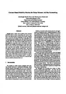
In this section, we discuss the evaluation of our implementation. We ran several experiments on the Emulab [6] testing framework to compare three message delivery protocols: DTN, sendmail (SMTP), and a simple file transfer program (SimpleFTP4 ). In one set of experiments, we examine the relative protocol overheads with no disconnections and verify that our implementation does not add significant overhead, achieving 90% of wire speed with certain message sizes. In second set of experiments, we add disconnection cycles and show that the core value propositions of the DTN architecture holds, and that message delivery in the presence of disconnection is vastly improved. We then begin to examine in more detail the effects of various message sizes in the presence of disconnections, and 4 We wrote our own file transfer program since the standard FTP protocol proved to be rather intolerant of disconnections and was challenging to configure to use a connection proxy at intermediate hosts due to the data port allocation.
10
100%
100%
% BW Utilization
% BW Utilization
DTN (HOP)
80%
MAIL (HOP)
60%
SFTP (HOP)
40%
DTN (E2E)
20%
SFTP (E2E)
MAIL (E2E)
DTN (HOP)
80%
MAIL (HOP)
60%
SFTP (E2E)
40% 20% 0% 1
0% 1 KB
10 KB
40 KB
10
20
40
60
100 1000
Message Size(KB)
100 KB
Message Size
Figure 8: Comparison trend of DTN, SimpleFTP and sendmail for different message sizes.
Figure 7: Bandwidth utilization percentage of different protocols.
last message to be delivered, we plot the ratio of the bandwidth used versus the total available link bandwidth. Several conclusions can be drawn from this experiment, most notably that in all of these message sizes, DTN has relatively low overhead, in several cases matching or even exceeding that of the other protocols. In particular, for the moderate message sizes of 10-40K, all the protocols (except mail). In fact, these results were initially surprising to us, in that we were surprised by how well DTN did compared to the other protocols on smaller messages. Analyzing these results, we realized that for all the protocols dependent on end-to-end exchanges (i.e. all protocols in the end-to-end configuration and SFTP through the plug proxy), due to the cumulative latencies of 50 ms total round trip time, the per-message exchanges dominates the cost of the transmission. This is true even though all protocols maintain a single open TCP connection for the entire experiment. In this case, the use of store-andforward minimizes the per-transaction latency. Note that SMTP is worse than DTN primarily due to more roundtrip exchanges and a higher per-message header overhead. As is shown in Figure 8, as the message size increases, the throughput for both DTN and SMTP begins to decrease. This is an expected characteristic of store-andforward networks, as the intermediate nodes cannot begin to forward the data for a message until the whole message arrives. However, it is important to note that this forwarding latency is a function of the largest message size and the network hop count, not the number of messages.
demonstrate the value of DTN fragmentation in improving throughput. We also briefly describe our experiences in implementing epidemic routing algorithms similar to those described in ZebraNet [10]. This evaluation demonstrations how the internal interfaces to support protocol experimentation are effective for qualitatively distinct approaches to routing.
6.1
Message Transfer Overhead
In our first set of experiments, we set out to measure the overheads of the DTN protocols on a well connected network, as compared to traditional Internet-style message transfer protocols. We configured a five node Emulab cluster in a linear topology, connected via links of 100kbps bandwidth and 5ms delay. As shown in Figure 6, we ran all protocols in two configurations. In the first (end-to-end), we only ran protocol daemons at the two end hosts; intermediate hosts simply performed IP forwarding. In the second configuration (hop-by-hop), all five nodes ran protocol daemons. For DTN, this is done via static route entries that forward all bundle traffic to the next hop in the topology. For sendmail, we configured the next hop as a “smart relay” to force traffic to flow along the topology5 . In the case of SimpleFTP, intermediate hosts ran a simple userspace plugproxy daemon to forward TCP connections to the next hop. Figure 7 shows the six protocol configurations when forwarding 2MB of data split into of 1KB, 10KB, 40KB and 100KB message sizes. The graph plots the bandwidth utilization percentage, i.e. given the time of the
6.2
Intermittency Tolerance
5 Using
smart relays avoids the complexity of setting up MX records. We also had to make some other non-standard configuration settings to make the performance of sendmail more fair (and vastly better under disconnections). This includes setting the queue scanning time to once every five seconds, setting the host status cache timeouts also to five seconds, and setting the SingleThreadDelivery option to keep down the machine load and send each file sequentially.
In this section we address the core value proposition of the DTN architecture, and verify that in the presence of intermittent connectivity, the DTN protocols result in significantly higher throughput as compared with the other protocols. 11
100%
14
MAIL (HOP)
# of messages received
% BW Utilization
12
DTN (HOP)
60%
SFTP (HOP) 40%
DTN (E2E) MAIL (E2E)
20%
SFTP (E2E)
0% Aligned
Shift
Sequential
Random
Link Pattern
14
MAX DTN (40K) DTN (HOP) MAIL DTN (E2E) SFTP
MAX
80%
10
12 10
8
8
6
6
4
4
2
2
0 0
240
480
720
960
0 1200
Time (s)
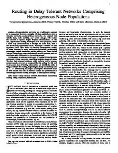
Figure 9: Bandwidth utilization percentage of different protocols with network disruption.
Figure 10: Cumulative message arrivals, using 200K messages and a 10 second phase offset demonstrating the effects of both proactive and reactive fragmentation.
For this set of experiments, we modified the previous configuration to introduced periodic disconnectivity to each of the links. All disruptions are cyclical, whereby each of the four links are up for one minute, then down for three. We fixed the message sizes at 40K, as our previous experiments showed that the protocols were most equivalent with that size.
6.3
Effects of Fragmentation
In Figure 10, we ran a single experiment with 200KB messages (i.e. a transfer time of around 16 seconds per message) and a 10 second phase shift scenario, and plot the cumulative message arrivals along with the theoretical maximum. We also include one experiment where the DTN configuration is set to pro-actively fragment the large payloads into smaller 40K bundles. The first thing to note is that the phase shift causes both of the end to end protocol variants to only achieve half the effective throughput as the hop-by-hop ones. This is fully expected – since again the end-to-end path is only available for 30 seconds (out of 60) per cycle. We note however, that DTN is able to deliver an extra message in every cycle. This is due to reactive fragmentation’s ability to take advantage of partial transmissions. A similar effect is also noted in the comparison between the hop-by-hop DTN and SMTP. Once again, DTN is able to deliver one extra message and stays ahead of sendmail at all times. We note that RFC 1845 [4] proposes a checkpoint/restart functionality for the SMTP protocol. However, to our knowledge, no implementations support this featur, but we would expect its adoption to resolve these differences. The final comparison is between the theoretical maximum and DTN configured to pro-actively fragment with 40K fragment sizes. While DTN does still lag behind the theoretical max due to the per-hop forwarding delays discussed above, once the initial latency is passed, it is able to take advantage of close to the full available bandwidth and concludes the transmission well before the non-fragmented case. This result underscores the value of fragmentation for efficient message delivery. This effect is also evident in the comparison to send-
Figure 9 shows the bandwidth utilization for four experiments in which we varied the phase of the cycles for each link. In this case, the link bandwidth is calculated to take into account the fact that each link is only active for 1/4 the time. Note that we also plot the maximum achievable rate for each of the experiments to reflect the fact that some of the bandwidth is necessarily wasted in some experiments since a node cannot send data that it has not yet received. In the aligned experiment, all four links were up at the same time. As is shown in the graph, the relative performance of the protocols matches their relative performance in the fully connected case described above. Note that to achieve these results for the non-DTN protocols we had to tune the kernel TCP retry parameters to be more aggressive while establishing connections. In the shift experiment, we moved the start offset phase for each link forward 10 seconds. As a result, the effective throughput of all the end-to-end protocols is correspondingly halved. These effects are even more obvious in the sequential configuration, where each link is up one after another. Since none of the end-to-end protocols can establish a connection, their throughput drops to zero. Finally, in the random experiment, the phase of each link starts at a random offset. Note that in all these experiments, both DTN and hop-by-hop sendmail achieve notably better performance from all the others, with DTN in particular remaining within 6% of the maximum achievable bandwidth in all cases. 12
PCs) provides some similar user-level features as BITNET, but can tolerate extended disconnection (it does not support real-time chat). While Usenet can operate over various underlying transport protocols, the historically most important one was UUCP (Unix-to-Unix Copy Program) [], which provides the underlying capability of remote asynchronous execution. UUCP is source routed, which ultimately became too unwieldy for most users so a somewhat automated approach was used. This approach used locally-stored UUCP link and link cost information (updated from time to time). Shortest (weighted) paths were computed from the local node to the intended destination Intermittent links have a higher cost but are not otherwise different from traditional direct links. DTN generalizes this on several fronts including dynamic routing, fragmentation, multiple paths, and time-varying links.
mail. Over the five cycles plotted, the DTN fragmentation is able to deliver an extra message due to the reassembled fragments from previous cycles.
6.4
Epidemic Routing Implementation
Our final evaluation section is more of a qualitative one to examine the effectiveness of the abstractions we designed for the routing module. One of us (who had not been involved in the design or implementation of the router interfaces) implemented the epidemic routing algorithms described in the ZebraNet project within the DTN router framework. We chose an epidemic routing algorithm primarily due to the fact that the decision making process is qualitatively different from that of a more traditional destination based router. In particular, the epidemic protocols require multicasting of bundles in response to opportunistic contacts where utility of the peers that are encountered decays with time. With little guidance from the rest of the team, this development was completed in less than two weeks, much of which was spent debugging the simulation framework. The basic primitives and interfaces matched the requirements for the algorithm well. As a final note, we validated the correctness of this implementation and our simulation framework by noting that our simulation results correlate to the same trends observed by the original ZebraNet description.
7
Asynchronous messaging (and the use of mail boxes) built upon one or more of the message delivery systems mentioned above and is generally implemented at the application layer as an e-mail MTA (mail transfer agent). By 1978, the US Army required electronic mail, prompting the creation of the MMDF mail delivery system and some underlying protocols to support it which essentially provided routing of ARPANET-style mail messages over regular phones lines. At about the same time, the sendmail MTA was developed. It provided relaying between multiple mail formats, while MMDF was focused on Internet-style mail. Perhaps ironically in retrospect, MMDF lost in popularity to sendmail because it was only able to handle Internet-style address and mail routing while sendmail could handle the multiple addressing varieties in use at the time. In particular, sendmail was able to tie together UUCP, Internet, BITNET, and MCI mail addressing formats.
Related Work
The DTN architecture is based on an abstraction of delivering messages between applications. There is a long history of protocols the deal with messages, so a complete history would be well beyond the scope of this paper. One of the earliest messaging networks, BITNET offered many services, including e-mail, semi-interactive chat, remote file access, and mailing lists. By the early 90’s it was the most widely used research communication network in the world for e-mail, mailing lists, file transfer, and quasi-real-time messaging. It originated as a form of overlay on top of the IBM VNET e-mail system and used the Remote Spooling and Network Job Execution protocols (RSCS and NJE/NJI, respectively). The system used only a tree structure for routing, and depended on these underlying protocols for reliability, etc. It used leased phone lines, which enabled relatively low latency message delivery. For many sites, such infrastructure was too costly, thereby effectively prohibiting their participation in BITNET. For sites lacking ’always-on’ connections, Usenet (and the similar FidoNet network popular on DOS based
Both sendmail and MMDF (and later MTAs such as MMDF2 and qmail) provide store-and-forward message operations, but employ underlying protocols for a significant portion of their function. Also, these agents typically do not make intelligent routing decisions. Rather, the infer directly from the addresses specified which message transports should be used. They also use static routing based on local tables. So, in effect, these systems do not try to take advantage of all forms of connectivity to convey a single message but instead attempt to multiplex and demultiplex messages onto their implied transports, while supporting store-and-forward operations in a single program. DTN adds dynamic multi-hop routing, fragmentation, support for multiple paths, and an explicit way to encode the names of other regions without “rewriting” rules. 13
8
Conclusions
References [1] A. Adya, J. Howell, M. Theimer, W. Bolosky, and J. Douceur. Cooperative Task Management Without Manual Stack Management, 2002.
While the experimental validation of the DTN architecture was in the end successful, we also learned several things along the way that we feel can apply to other research-oriented reference implementations.
[2] V. G. Cerf, S. C. Burleigh, A. J. Hooke, L. Torgerson, R. C. Durst, K. L. Scott, K. Fall, and H. S. Weiss. Delay-Tolerant Network Architecture. Internet Draft, March 2003. ftp://ftp.rfc-editor. org/in-notes/internet-drafts/ draft-irtf-dtnrg-arch-02.txt.
1. The implementation of a novel architecture will likely motivate refinements in the architecture that are unexpected from a conceptual level. The process of mapping the abstract DTN network model to a concrete implementation structures required fundamental new contributions at the architectural level as well.
[3] D. Clark and D. Tennenhouse. Architectural considerations for a new generation of protocols. In Proceedings of the ACM symposium on Communications architectures & protocols, pages 200–208. ACM Press, 1990.
2. The goal of a ”fully extensible” system is likely to be unattainable ; the best you can and should attempt to do is to enable extension and experimentation along a few pre-defined axes. For this prototype, we focused on research into the challenging problems of DTN routing and forwarding and have developed a rich toolbox of internal interfaces for both experimentation and deployment.
[4] D. Crocker. SMTP Service Extension for Checkpoint/Restart, September 1995. [5] Avri Doria, Maria Uden, and Durga Prasad Pandey. Providing Connectivity to the Saami Nomadic Community. In Development by Design Conference, 2002. [6] Emulab Network Emulation. http://www.emulab. net. [7] V. Cerf et. al. Interplanetary Internet (IPN): Architecture Definition. Internet Draft, May 2001.
3. Even seemingly simple operations, such as reliably sending a message over a TCP connection, become complex when operating in environments that do not match the assumptions of existing implementations and interfaces. We regularly underestimate the complexity of reusing existing components because of this. The fact that most OS code resides in drivers reflects an analogous problem.
[8] Kevin Fall. A delay-tolerant network architecture for challenged internets. In SIGCOMM, pages 27–34. ACM Press, 2003. [9] Sushant Jain, Kevin Fall, and Rabin Patra. Routing in a Delay Tolerant Network. In SIGCOMM, September 2004. [10] Philo Juang, Hide Oki, Yong Wang, et al. EnergyEfficient Computing for Wildlife Tracking: Design Tradeoffs and Early Experiences with ZebraNet. In Proceedings of ASPLOS-X, October 2002.
4. The effects of intermittency are rarely transparent and thus spans all layers of the system. An appropriate solution must reflect basic network state information and control far up the stack to the application, in contrast to the strict layering model and to the interfaces generally presented by networked systems.
[11] Alex Pentland, Richard Fletcher, and Amir Hasson. DakNet: Rethinking Connectivity in Developing Nations. In IEEE Computer, Jan. 2004. [12] DARPA’s proposed program for Disruption Tolerant Networking. http://www.darpa.mil/ato/ solicit/DTN/.
In addition to these general lessons, we conclude by noting that our implementation performs well with low overhead in well-connected environments as compared to traditional messaging protocols. Moreover, it soundly validates the core proposals of the DTN architecture and its mechanisms: that in challenging environments, a store-and-forward message overlay network performs significantly better than existing approaches, in some cases within a small percentage of the theoretical maximum achievable throughout.
[13] Rahul C Shah, Sumit Roy, Sushant Jain, and Waylon Brunette. Data mules: Modeling a three-tier architecture for sparse sensor networks. In SNPA, 2003. [14] Technology and Infrastructure for Emerging Regions (TIER). http://tier.cs.berkeley.edu/. [15] Rob von Behren, Jeremy Condit, and Eric Brewer. Why Events Are A Bad Idea. In HotOS, May 2003. [16] Randolph Y. Wang, Nitin Garg, Sumeet Sobti, et al. Postmanet: Turning the Postal System into a Generic Digital Communication Mechanism. In Proceedings of the ACM SIGCOMM 2004 Conference, August 2004. [17] Wizzy Project. http://www.wizzy.org.za/.
14