support customized application specific components for performance critical functions. While the performance of an FPGA based implementation is still.
Implementing Multi Threaded System Support for Hybrid FPGA/CPU Computational Components Razali Jidin, David Andrews, Douglas Niehaus Information Technology and Telecommunications Center Department of Electrical Engineering and Computer Science University of Kansas {rjidin,dandrews,niehaus}@ittc.ukans.edu}
Abstract Recently emerging hybrid chips containing both CPU's and FPGA components have the potential to enjoy significant economies of scale, while enabling system designers to include a significant amount of specialization within the FPGA component. However, realizing the promise of these new hybrid chips will require programming models supporting a far more integrated view of the CPU and FPGA components than provided by current methods. This paper describes fundamental synchronization methods and hardware thread interface that we are now developing for supporting a multi-threaded programming model that provides a transparent interface to the CPU and FPGA based component threads.
1. Introduction Recently emerging hybrid chips containing both CPU and FPGA components are an exciting new development that promise COTS economies of scale, while also supporting significant hardware customization. For example, Xilinx [4] offers the Virtex II Pro which combines up to four Power PC 405 cores with up to approximately 4 million free gates, while Altera [5] offers the Excalibur, which combines an ARM 922 core with approximately the same number of free gates. The free FPGA gates can be configured with a widening range of standard FPGA Intellectual Property (IP) system library components, including serial and parallel I/O interfaces, bus arbiters, priority interrupt controllers, and DRAM controllers. Designers now have the freedom to select a set of FPGA IP to create a specialized System-on-aChip (SoC) solution. These capabilities allow the designer to enjoy the economies of scale of a COTS device but based on a selected set of IP that produces a design tailored for their specific requirements. Additionally, the free FPGA gates may also be used to support customized application specific components
for performance critical functions. While the performance of an FPGA based implementation is still lower that that of an equivalent ASIC, the FPGA based solution often provides acceptable performance but with a significantly better price/performance ratio. Tapping the full potential of these hybrid chips presents an interesting challenge for system developers. Although the ability to program these hybrids with a standard set of FPGA IP to replace current COTS board designs with a single chip already exists, specifying custom components within the FPGA requires knowledge of hardware design methods and tools, which dangles the full potential of these hybrids tantalizingly out of reach for the majority of system programmers. Researchers are seeking solutions to this barrier by investigating new design languages, hardware/software specification environments, and development tools. Projects such as Ptolemy [2], Rosetta [9], and System-C [6] are investigating system level specification capabilities that can drive software compilation and hardware synthesis. Other projects such as Streams -C [3] and Handel C [7] are focused on raising the level of abstraction at which FPGAs are programmed from one of gate-level parallelism to that of modified and augmented C syntax. System Verilog [8] and a newly evolving VHDL standard [10] are also now being designed to abstract away the distinction between the two sides of the traditional low level hardware/software interface into a system level perspective. Although these approaches differ in the scope of their objectives, they all share the common goal of raising the level of abstraction required to design and integrate hardware and software components. A good question then, is if high level programming language capabilities for FPGA's continue maturing at current rates, will this be sufficient to allow software engineers to apply their skills across the FPGA/CPU boundaries? Unfortunately, current hybrid
programming models are still immature, generally treating FPGA's as independent accelerators with their computations outside the scope of the programs running on the CPU. Communications between the FPGA based and CPU based computations are generally through simple input/output queues, and the immaturity of the hybrid model does not provide for synchronizing the execution of the component computations: a critical capability in distributed and parallel computation. The addition of a high level programming model is needed that abstracts the FPGA/CPU components, bus structure, memory, and low level peripheral protocols into a transparent system platform [12]. In general, programming models provide the definition of software components as well as the interactions between these software components (see Lee [1] for a discussion of software frameworks for embedded systems). Message passing and shared memory protocols are two familiar forms of component interaction mechanisms in use today. Both have been successfully used in the embedded world and practitioners enjoy debating the relative merits of their personal choice. This paper presents work being performed in extending the multithreaded programming paradigm across hybrid architectures. Our FPGA based hardware thread interface enables hardware computations to interact with CPU based software threads in familiar multithreaded programming environment. Our synchronization mechanisms enable these hybrid threads to share data without data corruption. Software threads call program interface (API) to request for these synchronization mechanisms. This capability, coupled with recent advancements in hardware synthesis from high level languages will open up the potential of the reconfigurable hardware to system programmers.
2. Multithreaded Programming Model The multi-threaded programming model is convenient for describing embedded applications composed of concurrently executing components that synchronize and exchange data. Under such a multi-threaded programming model, applications are specified as sets of threads distributed flexibly across the system CPU and FPGA assets. The familiar multi-threaded programming model can greatly reduce design and development costs as the computational structure of hybrid applications at the highest level of abstraction remains familiar. Whether the threads implementing a computation are CPU-based or FPGA -based can become just one more of the available design and implementation parameters with resource use and application performance implications. How to perform
this partitioning to best support the needs of an application or system is yet another challenging problem currently being investigated. At this point it is appropriate to draw a distinction between policy and mechanism. The policy of the multi-threaded model is fairly simple: To allow the specification of concurrent threads of execution and protocols for accessing common data and synchronizing the execution of independent threads. On a general purpose processor, the mechanisms used to achieve this policy include the definition of data structures that store thread execution state information, and the semantics of how thread synchronization interacts with the operating system thread scheduler. Data structures for thread context and semaphore control are accessed by both the synchronization (semaphore) control and thread scheduling portions of the system software. Unlike general purpose CPU's, FPGA's provide no a priori computational model. Although the lack of an existing computational model at first glance seems to be a liability, instead it is an asset because it presents an opportunity to create efficient mechanisms for implementing FPGA threads and for supporting thread synchronization within the FPGA and across the CPU/FPGA boundary. A key aspect of the multithreaded programming model is the ability for independent threads to co-ordinate execution and share data using standard synchronization primitives. We present our work in designing and preliminary testing of hybrid thread synchronization mechanisms that can be used in embedded systems that contain both hardware and software threads. A significant aspect of our approach is our ability to achieve the base synchronization semantics, but without relying on traditional assembly language conditional instructions, or additional memory coherence mechanisms. This is critical point as new evolving computational models being developed for hardware threads will not need to adhere to these processor family dependent instructions and memory coherence system capabilities, thus simplifying system design.
3. Hybrid Thread Creation Current thread packages provide API calls for creating a thread. The thread call results in the creation of a data structure to capture the threads context, and a call to the thread scheduler. We have adopted a similar method for creating a hardware thread. Our API for creating a hardware thread is shown in Figure 1. In software based multithreading packages, the thread creation API's does not provide immediate execution
of the thread on the CPU. Instead, the API contains a call to the thread scheduler that may or may not immediately run the new thread. In contrast, a hardware thread is an independent computational comp onent and can be immediately started. The hardware thread initiates execution by writing into a command register as shown in Figure 2. hw_thread_start(&thread_id) { command_register ß cmd_run } hw_thread_stop(&thread_id) { command_register ß cmd_stop } Figure 1.Pseudo code for hardware thread creation API
3.1 Hardware Thread Hardware threads are composed of two components; a user-developed hardware thread component, and a hardware thread interface component. The userspecified hardware thread component contains the computations specified by the application programmer. The user specified hardware thread component is synthesized and preloaded into the FPGA. The semantics of starting the thread during run time consists of the writing of a command word into the command register within the thread create API. The hardware thread interface, which includes the command register, status register and interface logic to the bus is a library routine linked in by the user. This approach was developed to promote portability and platform independence of the user computation from the underlying platform. The thread interface can operate as both a bus master and slave for the user hardware component. When functioning as a master, the user thread can initiate a write or read to memory across the bus transparent to the user thread.
CPU
data bus
Semaphore IP
Hardware Thread Interface
request
command
owner
status
cntlr release
operation
User Hardware Computation Thread
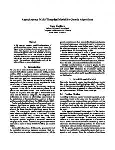
Hardware Thread IP: 1. CPU can start/stop a hardware thread via command register. 2. Hardware thread submits a request to the operation register. 3. Controller performs requested operation and 4. Controller updates the status register. 5. Hardware computation thread polls status register. 6. Depending on the status register, computation proceeds to next state. Semaphore IP: 1. To acquire a semaphore, thread writes its thread_id to request register. 2. Thread checks owner register if it owns the semaphore. 3. To release owned semaphore, thread writes its thread_id to the release register. CPU: 1. CPU based threads use API to request/release a semaphore.
3.1.1 User Threads Our current approach provides a state machine template for users to specify their application. Should the computation require access to a shared buffer, it can obtain a semaphore via the interface. This state machine framework was defined to support semaphore semantics, where an application will either spin or suspend waiting on an application. The semantics of a spin or wait are easily implemented within a state machine approach by defining separate states for the application before and after execution of the semaphore. The user state machine interfaces to our interface control logic, by writing a specific code into the operation register and then waiting for an acknowledgement signal via the status register from the interface. User threads request different types of services from the interface control logic by writing unique op_codes into the command register. 3.1.2 Hardware Thread Interface The interface library component has two interfaces. The first interface is platform specific and generates appropriate bus interface logic. The second interface is platform independent and interfaces to the user developed hardware computation. The interface component is implemented as three sub components; a CPU interface, a hardware thread state controller, and a user hardware computation interface.
Figure 2. Hybrid (FPGA+CPU) Thread System Once initiated, hardware threads may execute independently, synchronize and share data with all other threads using semaphores.
The CPU interface contains a bus interface, and command and status register set. The bus interface has the capability to switch from the bus slave to bus master mode. As a bus master, bus transfers can be
requested on behalf of the user thread. The bus interface component was designed to be bus architectural independent, as it requires only standard read and write signals. The register set enables the CPU or any other bus controller to interact with the user hardware thread. An application thread running on the CPU may write to the command register to start or stop the hardware computation. This capability is particularly useful for debugging purposes and to wake-up a blocking thread. A CPU based application thread may also inspect the status register to determine the state of the hardware threads current execution. reset user state machine writes to operation register usr_stop
idle
CPU writes to command register cmd_run
transit run cmd_stop CPU writes to command register
lock_request
wait lock_rel_ack
hw thread waits for lock or semaphore
variables and shared resources. It updates the status register with its super-state, which provides status to the user thread. To service the user thread, the controller reads the operation register, and depending on the current state of the command register, will perform the requested operation and update the status register accordingly. The controller super state represents the current execution state of the hardware thread. Current allowable thread states include IDLE, RUN, and WAIT as shown in Figure 3. The thread scheduler manages the transitioning between these thread states during the lifetime of the thread. The super-states are visible via the status register to all other threads. User computations are treated as autonomous threads and regulated by the controller. This implies that a user computation may decide when it is appropriate to check the status register and control it's own operation. This allows the independent hardware threads to be stopped by a controlling CPU based thread. This approach was adopted to ensure that user threads are able to stop gracefully and at its safe states. For example if the controller receives a stop command from other IP or CPU, it will not force thread to stop immediately but it will reconcile with the user thread state machine. The controller will go into a transit state waiting command or operation register to change.
lock_req_ack
release lock
run wlock
Figure 3: State Diagram for Hardware Thread The user interface sub component provides interfacing services to the user hardware computation. The user state machine may submit requests via this interface to seek services from the controller. This interface logic is composed of operation, parameter and status registers. The function of the operation register is analogous to the POSIX software thread synchronization library API calls. For example when performing a semaphore operation, the user hardware logic writes a specific code into the operation register. The user state machine may then poll the status register to check if the semaphore has been granted. When the semaphore is obtained, the user state machine can proceed with subsequent operations, such as updating the shared variable located in memory. The thread state controller manages a thread "super state", reconciles CPU commands with the user state machine, and provides services to the user computations. The thread state controller functions as a server for the user thread to access synchronization
4. Hybrid Thread Synchronization Semaphore implementations on general purpose CPU's are based an atomic read and (conditional) write of a shared variable. In modern multiprocessor implementations, these operations occur as dependent pairs of conditional instructions, such as load linked and store conditional [11]. These instructions require additional control logic within the CPU that interfaces into the memory coherency policy of the system. While semantically correct, these existing mechanisms introduce significant complexity in the system design that is not easily portable when creating parallel hardware threads. Instead of replicating these mechanisms , we use the FPGA to implement more efficient mechanisms that are CPU family independent, and require no additional control logic to interface into the system memory coherence protocol. As such, our new mechanisms are easily portable across shared and dis tributed memory multiprocessor configurations. The basic mechanisms defined use a standard write of a thread id into a memory mapped request register. We define a simple control structure within the FPGA that conditionally accepts or denies the request. The thread requesting the write then performs a read operation of an "owner" register to see if it's thread_id
has been accepted as the new owner of the lock. This basic policy is the core upon which more complex synchronization mechanisms are constructed. The design of binary and counting semaphores, both busy wait and blocking, are presented below.
spin_unlock(&sema, thread_id) { release ß thread_id }
4.1 Binary Spin Lock Semaphores
Figure 5. Spin Lock pseudo code API
The block diagram for a binary spin lock semaphore is shown in Figure 4. The API pseudo code for accessing the binary spin lock is given in Figure 5.
4.2 Spin lock counting semaphore The block diagram of the counting semaphore is shown in Figure 6. The user API pseudo code for accessing this structure is shown in figure 7.
Data Bus
Lock_own Rqst Release
Spin Lock Cntrl
Figure 4. Spin Lock Binary Semaphore The basic semantics of all API's for accessing the lock are implemented identically in both hardware and software threads, and are made available as library routines to the system developer. To request the semaphore, the API first writes the thread_id into the request register. After the thread_id has been written, the API then reads back the lock_own register and compares to see if it's thread_id is now the lock owner. To release the semaphore, the thread writes it's thread_id into the release register. When a thread_id is written into the request register, if the semaphore is free, then the control logic implemented as a state machine within the semaphore IP updates the lock_own register. If the semaphore is currently locked, then the control logic performs no update. After the first access, the lock is only freed when a thread writes into the release register. spin_lock(&sema, thread_id) { grant = 0; while(!grant) { rqst_reg ß thread_id If lock_own == thread_id) then grant = 1; else delay end while }
4.2.1 Request The thread first gains access to the counting semaphore registers by accessing the binary spin lock. The binary spin lock protects the next two instructions that first write the requested number of resources and then reads back a status. A requesting thread writes its request for a number of resources into the rqst_num register. The semaphore IP then checks to see if sufficient resources are available and sets the grant register. If insufficient resources are available, then a boolean value of 0 remains in the grant register. If sufficient resources are available, then the boolean value of 1 is written into the grant register. In either event, the thread reads the result of the request from the grant register. 4.2.2 Release A thread can release any number of resources by writing into the rel_num register. Note that no accessing of the spin lock is necessary for releasing resources. Data Bus
Max_count
grant 0:1
Lock_own
Rqst_num
Rqst
Rel_num
Release
Counting Spinlock Semaphore Control Logic
Spin Lock Cntrl
Figure 6. Counting Semaphore spin_count(&sema, value) { grant = 0; while (!grant) spin_lock( ) rqst_num ß value grant ß grant0:1 spin_unlock( )
if (!grant) delay end while } spin_count_rel(&sema, value) { rel_num ß value } Figure 7. Spin Counting Semaphore API 4.2.3 Spin Count Semaphore Logic The count register is initialized by the operating system during system initialization and is not needed further by running threads. However, the count register can be reset at any point without requiring a system reboot. After a thread gains access to the controlling spin lock, two ordered operations take place. First, the requested number of resources is written into the request register, which is then subtracted from the current count register. After the number or requested resources have been latched, the grant register is updated with a Boolean value reflecting if the subtraction resulted in a value greater than or equal to zero, or less than zero. If the result was less than zero, then insufficient resources were available, and no further action is required. If the result was greater than or equal to zero, then the grant flag is set to one and the subtracted value is loaded into the count register. The semaphore IP logic will clear the grant register value (set it back to 0) upon a read it. 4.2.4 Release Operation To release resources, the thread writes the number of resources to be released into the release register. No access of the binary semaphore used by the requesting threads is needed to release resources. Obviously, only one thread will be allowed access to the semaphore IP registers during any bus cycle. Assuming the requesting thread is the current bus owner, the request value is latched at the end of the cycle and will be available to the logic circuits the next clock cycle. If an immediate request for resources during the next clock cycle, the semaphore IP performs the subtraction and sets the grant flag. That flag will stay valid for the request and will not change until the requestor performs the reading of the grant flag. No other requester can cause the recalculation to occur as the request/grant check pair are protected by the spin lock. Even if these two sequential operations are interrupted by a valid release request, the grant flag will not be affected and will still reflect the value of the count when the requesting task entered into the spin lock, there bye in fact, providing the same semantics as a shared lock.
4.3 Blocking Semaphores
Blocking semaphores allow threads that cannot gain access to a semaphore to be queued and suspended thus providing more efficient usage of the computing resources and decreasing congestion on the system bus. Our basic mechanism includes queue structures to be associated with each blocking semaphore to hold onto thread ids that are suspended as shown in Figure 8. The release of a blocking semaphore by the current owner is an event trigger from the semaphore IP that may cause granting of the released semaphore to a new owner if a thread is suspended on that particular semaphore. The event trigger must interface to both hardware threads and the operating system. If no thread is suspended, then obviously no change of ownership is required. The semaphore IP itself has the capability of choosing from a queued list of threads whom to grant the semaphore to next. With queues residing (conceptually) within each semaphore the control logic can issue only one (achieving a traditional queuing semaphore), or multiple threads (implementing generic sleep wakeup) when the lock is either freed in the binary case, or resources are returned in the counting semaphore case. In both cases, the centralized interface structure shown below is provided to simplify the interface between the CPU and hardware thread components, and the individual semaphores. This structure simplifies the interface logic needed for the blocking semaphores to interact with the CPU and hardware thread components, and also reduces the complexity of the interrupt service routine running on the CPU required to query the multiple semaphore components. The structure provides an initial separation between hardware and software threads to eliminate unnecessary context switching on the CPU when a hardware thread is being awakened. The structure forms a basic framework to support our longer term goal of migrating system scheduling decisions from the CPU into hardware.
4.3.1 Blocking Binary Semaphores The API writes a thread id into the request register and then follows up with checking the owner register similar to the binary spin lock. If the thread did not receive the lock, then the API puts the thread to sleep. Once wakened, the thread will read owner register. The lock is released by writing the thread_id into the release register.
Interrupt
block_bin_rel(&sema, thread_id) { release ß thread_id }
DataBus
Figure 10. Blocking Binary Semaphore API blocking Semaphore
Interface/ Access Logic
blocking o o o blocking Semaphore Semaphore
System Scheduling Component
o o
o o
CPUReady Que HardwareThread Ready Que
Figure 8. Blocking Semaphore and Interface Framework The depth of the request queue for our prototype is a system design parameter set at design time. The block diagram of blocking binary semaphore system components is shown in Figure 8. The block diagram of a blocking binary semaphore is shown in Figure 9. The API for requesting a blocking binary semaphore is shown in Figure 10. 4.3.1.1 Request Each thread requests the lock by writing to the request register. If the lock is free, the control logic will update the lock owner register in a single cycle following the request. If the lock is owned by another thread, the control logic queues the request in the next clock cycle. No race conditions for the lock can occur with this policy.
4.3.1.2 Release A release is initiated by the writing of the thread id into the release register. If the queue has entries, the control logic will invoke the ready thread scheduler logic to select which queued request or requests show be signaled to the system as available for rescheduling and signal the event to the system. The event signaling method from within each semaphore consists of writing out thread_ids to ready to run queues: one for the CPU and one for the hardware threads. 4.3.1.3 Ready Thread Logic Policy The ready thread logic is a generic module that can be tailored to support any particular scheduling algorithm based on specific system requirements. For our prototype, we have implemented a basic protocol that copies the thread_id/&command_register to one of two global memory mapped ready to run queues, one for the CPU, and one for hardware threads. Writing into these queues causes an appropriate mechanism to occur that alerts the receiving component (either the CPU or a hardware thread) that new ids have been queued and are ready to be rescheduled.
4.3.2 Blocking Counting Semaphores Data Bus
request
Lock_own
Release
Rqst Spin Lock C ntrl o o o
Ready Thread Sched
Figure 9. Blocking Binary Semaphore block_bin_lock(&sema, thread_id) { grant = 0; while(!grant) { rqst_reg ß thread_id if(lock_own == thread_id) then grant = 1; else sleep( ) end while }
The block diagram of blocking counting semaphore is shown in Figure 11. The API pseudo code for blocking counting semaphore is shown in Figure 12. With the blocking counting semaphores if the resources are available, the thread continues to run. However, if insufficient resources are available, then the thread will be queued and suspended. The semaphore IP will consider issuing queued thread_ids for rescheduling only when resources are released. Implementing blocking semaphores within the hardware provides significant latitude in creating flexible system scheduling policies. We discuss two sample approaches to selecting thread_id's from the suspend queue for scheduling. In the first approach, one or multiple threads that are requesting resources equal to or less than the number that are available will be considered, and in the second approach all threads queued, independent of the number of resources reallocated, will be considered. The first approach will reduce the number of context switches and contention for the semaphore, and supports a system scheduling policy of giving priority to tasks that request fewer resources. The second approach considers all queued
thread_ids, and allows the scheduler(s) maximum flexibility in the scheduling decision. Our semaphore IP logic provides a scheduling component that can be tailored to specific system policies. To implement the first approach, the semaphore IP needs to hold onto the number of resources requested, and additionally needs to queue associated thread_id/&command_registers. To implement the second approach, the queue holding the requested number of resources is removed. If the thread needs to be blocked, only the thread_id is queued.
DataBus req_reg grant 0:1 thread_id thread_id thread_id thread_id
rst_num Rel_num rst_num rst_num rst_num
o o o thread_id
o o o rst_num
Lock_own
Max_count
Rqst Release
CountingSpinlock SemaphoreControl Logic
Spin Lock Cntrl
resume threadscheduler
Depends on Policy
5. Results We have performed tests to verify the functionality of our semaphores. Among the test performed were hybrid threads competing for semaphores, counting semaphore operations, and blocking semaphores’ release event interrupt mechanism. In addition we have evaluated hardware thread semaphore access time performance against software threads in acquiring our semaphore mechanism. We constructed an experiment setup as depicted in Figure 1 with additional programmable timer hardware to perform this test. The test was setup with all hardware including CPU, data bus and FPGA using a common 100Mhz clock. Our tests indicate that hardware threads can access semaphores 6.8 times faster than software thread. Software threads required 460 clock cycles, compared to 68 clock cycles needed by the hardware thread to complete one task test sequence. While synchronization operations may represent only a small percentage of CPU time in a typical application program, this test provides us early insights to potential fairness and starvation that may occur between hardware and software threads.
6. Conclusion
Figure 11. Blocking Counting Semaphore
4.3.2.1 Operation Just as in the spin lock protocol, writing a value into request number register causes a Boolean value to set in the grant register. If insufficient resources are available, then the thread_id needs to be sent before the spin lock is released. The semaphore IP will associate the next thread_id written with the request number that is kept latched in the request_num queue. block_count(&sema, thread_id) { grant =0; while (!grant) { spin_lock( ) grant ß grant0:1 if (grant) spin_unlock( ) else { queue thread_id/&command_reg spin_unlock( ) sleep( ) } end while } Figure 12. Blocking Counting Semaphore API
Significant advances in fabrication technology are providing new commercial off the shelf components that combine a general purpose CPU and reconfigurable logic gates (FPGAs). These new devices are a significant step toward realizing a single component that can support both the generalization of commercial off the shelf components and specialization required for individual embedded applications. Enabling the multi-threaded model across the hybrids components will allow programmers access to the power of the reconfigurable logic, and provide shorter design times and lower development costs. We have presented the design and preliminary test results of our thread interfaces and key synchronization mechanisms, necessary to support multi threading on hybrid CPU/FPGA platforms. We are currently working on a hardware based thread scheduler to support the movement of system services from the CPU into hardware. The work is partially sponsored by NSF EHS contract # CCR-0311599
7. Bibliography [1] Lee, Edward, "Whats ahead for Embedded Software?", IEEE Computer, Sept 2000, pp. 18-26
[2] Lee, Edward, Overview of the Ptolemy Project, Technical Memorandum, March 6, 2001, UCB/ERL M01/11 University of California [3] Maya B. Gokhale and Janice M. Stone and Jeff Arnold and Mirek Kalinowski, Stream-Oriented FPGA Computing in the Streams -C High Level Language, Proceedings of the Eight Annual IEEE Symposium on Filed-Programmable Custom Computing Machines (FCCM), April 2000, pp. 49-56 [4] www.xilinx.com [5] www.altera.com [6] www.systemc.org [7] www.celoxica.com [8] www.eda.org/sv-cc/ [9] Perry Alexander and Cindy Kong, Rosetta: Semantic Support for Model Centered Systems Level Design, IEEE Computer, November, 2001, pp. 64-70 [10] www.eda.org/vhdl-200x/ [11] Hennessey J.L., and Patterson, D. A., "Computer Architecture: A Quantitative Approach", 3rd Edition, Morgan Kaufmann, 2003 [12] Andrews, D.L., Neihaus, D., Ashenden, P. " Programming Models for Hybrid FPGA/CPU Computational Components:", IEEE Computer, January 2004