2015 International Telecommunication Networks and Applications Conference (ITNAC)
Improved Detection of Primary User Emulation Attacks in Cognitive Radio Networks Fan Jin, Vijay Varadharajan, Udaya Tupakula Department of Computing Macquarie University Sydney NSW 2109 Email:
[email protected],
[email protected],
[email protected] Abstract—Modern society heavily depends on wireless spectrum for communication purposes. With the rapid increase in mobile devices and Internet of Things (IoT), the need for wireless spectrum has grown dramatically resulting in the limited available spectrum becoming a constrained resource. To remedy this spectrum scarcity, cognitive radio (CR) was proposed as an efficient and opportunistic use of the frequency spectrum in order to increase spectral efficiency. However dynamic sharing of the spectrum between multiple users poses several significant challenges in security and trust. In this paper, we focus on primary user emulation (PUE) attacks in cognitive radio networks (CRNs). We propose a new scheme that we believe could be useful in practice to achieve an improved PUE attack detection in CRNs. The scheme combines energy detection and localization. One of the distinguishing features of the proposed scheme is that instead of detecting received energy level with a single threshold for a secondary user (SU), multiple thresholds have been used for each SU and the global decision is concluded by the majority of participating SUs. Furthermore, in cases where the primary users (PUs) are stationary and their coordinates are already known to SUs, we have combined our improved energy detection with a TDOA localization scheme for detecting PUE attacks. Our simulation results show that this scheme increases the level of accuracy in detecting PUE attacks.
I.
I NTRODUCTION
Our modern society heavily depends on the wireless spectrum for communication purposes. Telecommunications, financial transactions, military services and environment surveillance are just some of the numerous applications that are used in our daily life. The increasing demand for these applications require reliable access to spectrum at a reasonable cost. However, with the rapid increase in the number of mobile devices and their requirements for the spectrum, the limited available spectrum becomes a constrained resource and has been unbalanced utilized. One of the main reasons for spectrum scarcity is due to static spectrum allocation policy. The government agencies assign wireless spectrum to licensed holders on a long-term basis for large geographical regions. Such assignments have resulted in fierce competition for the use of wireless spectrum. To remedy this spectrum scarcity issue, cognitive radio network (CRN) [1] was proposed as an efficient and opportunistic use of the frequency spectrum in order to increase spectral efficiency. A cognitive radio network (CRN) is an intelligent network that contains both licensed users and unlicensed wireless users who have cognitive capabilities. These users are referred to as primary users (PUs) and secondary users
978-1-4673-9348-5/15/$31.00 ©2015 IEEE
274
(SUs) respectively. The CRNs help to address the problem of spectrum shortage by adapting to dynamic changes in their environment to make efficient use of the radio spectrum. CRN enables SUs to use the spectrum without interference to the PUs. This has to be achieved without any modifications or interactions with the PUs. However, As many other new techniques, in the initial period of adoption, the security issues in CRN have not been properly addressed. Compared with the traditional radio, CRN is more flexible and exposed to the wireless network medium. As a result, there are more security threats and attacks in CRNs than in a traditional radio environment. Primary user emulation (PUE) attack is one of the wellknown malicious attack specific to CRNs. It comes from attackers who want to spoof or mask the PU. The attackers provide a feint of the channel will be used by a PU. Hence the SUs within the transmitting range will believe a PU is active, and vacate the channel. As a result, the attacker can obtain the full bands of a given spectrum without having to share them with other SUs. A successful PUE attack may force legitimate SUs to quit current channel and look for another available channel, or occupy the idle channels and waste the spectrum opportunities of the SUs. Therefore, the key to mitigate PUE attacks is being able to distinguish PU signals from SU signals in a robust way. The ability to emulate the power levels of a primary signal is crucial for PUE attackers since most of the SUs employ an energy detection technique in spectrum sensing. A power-fixed attacker uses an invariable predefined power level regardless of the actual transmitting power of the PUs and the surrounding radio environment. Compared to the power fixed attacker, the power-adaptive attacker is smarter in the sense that, it could adjust its transmitting power according to the estimated transmitting power of the primary signal and the channel parameters [2]. Specifically, the attacker employs an estimation technique and a learning method against the detection by the legitimate SUs. It is demonstrated that such an advanced attack can defeat a naive defense approach that focuses only on the received signal power. The location of a signal source is also a key characteristic to verify the identity of an attacker. A static attacker has a fixed location that would not change in all round of attacks. By using positioning techniques such as Time Difference of Arrival (TDOA) or dedicated positioning sensors [3], the location of a static attacker could be revealed. A static attacker will be
2015 International Telecommunication Networks and Applications Conference (ITNAC)
easily recognized due to the difference between its location and that of the PUs. A mobile attacker will constantly change its location so that it is difficult to trace and discover. A viable detection approach that exploits the correlations between RF signals and acoustic information is proposed in [4] to verify the existence of a mobile PUE attacker. In this paper, we mainly focus on the security problem arising from Primary User Emulation (PUE) attacks. We will propose a scheme for improved detection of PUE attacks in CRNs and show that our scheme can be used in practise. The remainder of the paper is organized as follows. In section II, a revised energy detection is proposed and combined with TDOA localization for both fast and reliable detection. Section III discusses the defense approach against PUE attacks and the conclusions of the paper are presented in Section IV. II.
of a typical TV tower and the difference cannot be emulated by changing the output power of attackers. Furthermore, we assume the transmitted signal power is much higher than that of the SU or the environmental noise level in the system while PU or PUE attacker is transmitting and there is only one PU or PUE attacker is transmitting in the network at any given time.
I MPROVED PUE D ETECTION S CHEME
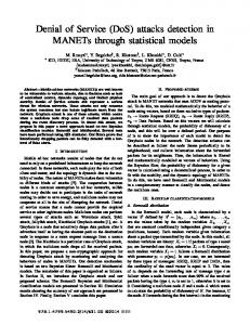
In this section, first we propose an improved energy detection method. Then we propose a novel PUE detection schemes using a combination of our improved energy detection with localization. The proposed PUE detection scheme combines energy detection with localization, which resolves above problems by increasing the accuracy of energy detection and estimating the actual location of signal source. The benefits of our approach includes the following: (i) robustness in the presence of noise; (ii) a significant improvement in accuracy of energy detection by using multi-thresholds and distributed results collecting. (iii) the exact location of PUE attacker can be identified. A. Architecture Overview and Assumptions As shown in Figure 1, we consider a CRN with PUs, SUs, PUE attackers and base stations that are distributed in a certain transmitting range. We assume all PUs in the CRN are fixed and their locations are known to the public. A classic example is the TV networks. In such CRN, the PUs are assumed to be a network composed of TV signal transmitters (i.e. TV broadcast towers). A TV towers transmitter output power typically has hundreds of thousands of Watts [15], which corresponds to a transmission range from several kilometres to tens of kilometers. SUs are hand-held devices that have CR capabilities and are located in the PUs transmission range. Each SU is assumed to have a maximum transmission output power that is within the range from a few hundred milliwatts to a few watts, which typically corresponds to a transmission range of a few hundred meters. We also assume there is a certain number base stations that are distributed throughout the network. These base stations are time synchronized and are capable of detecting the time difference while a signal is received. They can also exchange information with each other and SUs using a reliable communication channel. Moreover, each base station is equipped with a GPS unit and knows its own location. Finally, the base stations can themselves be SUs in the CRN. PUE attackers can be either selfish or malicious. A PUE attacker can be either a mobile or a fixed device equipped with a CR and is capable of changing its modulation mode, frequency and transmission output power. However, the attackers signal strength is several orders of magnitude smaller than that
275
Fig. 1: A CRN with fixed PUs and a mobile PUE attacker.
B. Improved Energy Detection Scheme Let x(t), h(t) and n(t) denote the transmitted signal, channel impulse response and the thermal noise of the channel between the transmitted signal and the receiver respectively. Moreover, let s(t) and s0 (t) denote a real PU signal and a PUE attacker’s signal. Then the transmitted signal x(t) = s(t) for the real PU signal, x(t) = s0 (t) for the signal from the PUE attacker and x(t) = 0 when only SUs are transmitting or there is no signal in the channel. The three possible received signals can be described as follow: n(t) h(t) ∗ s(t) + n(t) y(t) = h(t) ∗ s0 (t) + n(t)
SU or none PU PUE
where y(t) is the received signal at the SU that is acting as the PUE detector. Our improved energy detecting algorithm will differentiate these three cases by using the energy value received on each SU with multiple thresholds, which is different from conventional energy detection that uses only one threshold. First, for each time interval, all SUs involved in energy detection scan the frequency channel. Let ns denote the number of samples received by a SU i in one sensing period. After sampling, squaring and aggregation, the signal preprocessing unit generates the sampled energy vector e = e[n](n = 1,P 2, · · · , ns ) and the aggregated energy value E, n which E = 1 s e[n]. After that, the aggregated energy E is sent to our energy detector for a comparison to a predefined threshold θ0 . If E is less than θ0 , it indicates there is no signal or there are only SU signals present in the channel, which is the situation that x(t) = 0. Otherwise, we set up two new thresholds, denoted by θ1 and θ2 . Here, θ0 < θ1 < θ2 . The two new thresholds θ1 and θ2 are used to distinguish the signal from a PU or a PUE attacker. If the input θ0 < E < θ1 or E > θ2 , it is decided that a PUE attack is detected. If the input θ1 < E < θ2 , the transmitted signal is diagnosed to
2015 International Telecommunication Networks and Applications Conference (ITNAC)
be a PU signal. After comparing with predefined thresholds locally, local decision on each SU will be sent to a base station and compared with the aggregated result from other SUs. Assuming there are M SUs and the local decision for each SU is 1 if it decides a PU’s signal is present and 0 otherwise. Denoting Di as the every local decision andPDM as M the aggregated results observed by M SUs, DM = 1 Di . For an unknown signal, the global decision can be described as:
( rglobal =
1 0
DM >= M 2 DM < M 2
where rglobal is the global result concluded by all SUs. In a conventional energy detection, there is only one threshold to distinguish the presence or absence of a primary signal. However, a PUE signal tries to emulate the transmitting power of a real PU and hence this single threshold detector is not efficient for detecting a PUE attack signal. Our proposed multi-threshold detector provides a capability and a higher probability to distinguish whether the signal is from PU or PUE. Furthermore, introducing local decision and global decision is based on the following principle. It is difficult for the attacker to fabricate a signal so that all of the SUs receive the signal with the power level similar to that of the real PU. In other words, if the majority of the SUs decide the signal is from a potential PUE attacker, then the global decision that the PUE attacker is present will be made. Therefore, by randomly assigning (M ) SUs to measure the received signal power, letting these SUs know the signal power of the real PUs and exchanging the local decisions made by them for generating a global decision, a PUE attack can be identified with a high probability Generally, for each SU, the received energy E has the form of a Chi-Square distribution. Since the number of samples is large in most cases, we can use the Central Limit Theorem (CLT) to approximate the Chi-Square distribution by a Gaussian distribution. Let H0 ,H1 and H10 denote the hypothesis of receiving no signal, a real PU signal and a PUE attack signal, respectively. Let Pd (θ1 , θ2 ) and Pf (θ1 , θ2 ) denote the PUE attack detection and false alarm probabilities, respectively. We have Pd (θ1 , θ2 ) = P {θ0 < E < θ1 )|H10 } + P {E > θ2 |H10 }, and Pf (θ1 , θ2 ) = P {θ0 < E < θ1 )|H1 } + P {E > θ2 |H1 }. In practice, the three thresholds is set based on the signal propagation model, geographical environment and environmental noise level. The threshold values vary for energy detectors in different locations. Though our modified energy detection scheme significantly improves the possibility of successful PUE detection, attackers can still deceive SUs due to the reconfiguration ability of CR, either by changing their transmitting signal strength or transmitting location. Therefore, in order to provide a further enhancement to the success rate, we combine the improved energy detection scheme with localization that will be discussed in the following sections.
276
C. Implementation of Time Difference of Arrival (TDOA) Localization Scheme Besides energy detection, locating the signal source is another way to identify the PUE attacks in CRN, especially when PUs are fixed and their geographic information is already known to SUs. Several localization schemes have been proposed in previous research such as Time of Arrival(TOA), Time Difference of Arrival(TDOA), Angle of Arrival(AOA) and Received Signal Strength(RSS) based localization. TOA uses the travel time from the transmitter to the receiver and requires the transmitting signal includes the transmitting time. This approach violates the non-modification requirement and hence cannot be used in CRN. AOA requires localization devices to equip with ominidirectional antenna array because it locates the signal source by determining the angle of incidence at which signals arrive at the receiving node. Such hardware cost is not feasible in the system design. Moreover, AOA suffers from decreased accuracy and precision when confronted with signal reflections from surrounding objects since it only works well in situations with direct line of sight. RSS based localization does not require additional hardware expense, but it needs multiple location aware nodes to be widely distributed in the signal transmitting range, which may incur a big cost or management issues. SUs can be used as the sensing nodes when RSS localization is utilized but it can not be guaranteed that there are enough SUs in the network in a given moment for an accurate estimation. TDOA is suitable in CRN since it utilizes the difference between the arrival times of pulse transmitted by an emitter without any knowledge of pulse transmit times; it is a non-interactive localization scheme. Furthermore, it does not require base stations to equip with extra ominidirectional antenna array like AOA. Finally, the base stations update SUs which require such information as soon as the signal source is localized. Therefore, the system delay can be effectively reduced because the limited number of base stations and communication hops between base stations and SUs. The requirement of TDOA is that all the base stations have to be time synchronized for accurately detecting the time difference when a same signal pulse is received. This issue is not unsurmountable since GPS time synchronization techniques can be utilized at the base stations, this also incurs low cost. Therefore, a generic TDOA localization scheme is used to detect PUE attacks in our model. First we use Euclidean Distance to describe the distance between the signal source and base stations as below, (x − xi )2 + (y − yi )2 + (z − zi )2 = m2i , (i = 1, 2, . . . , n) (1) where (xi , yi , zi ) are the known coordinates of the base stations, mi (i = 1, 2, ..., n) are the range estimations between signal source and base stations respectively. n is the number of base stations. The coordinates of the signal source to be estimated are referred to as (x, y, z). Then we assume all the TDOA is measured with respect to the first base station. Therefore, mi,1 = ri − r1 , (i = 2, 3, . . . n)
(2)
2015 International Telecommunication Networks and Applications Conference (ITNAC)
where mi,1 (i = 2, 3, . . . n) are the TDOA range estimations. ri (i = 2, 3, . . . n) are the unknown parameters of true distances between the reference nodes and the target node. n is the number of the reference nodes. Combining (1) and (2) we can get following equations:
D. Proposed PUE Detection Scheme: Combined Energy Detection and Localization
(x − x1 )2 + (y − y1 )2 + (z − z1 )2 = r2 (x − x )2 + (y − y )2 + (z − z )2 = (r + m )2 2 2 2 1 2,1 ··· (x − xn )2 + (y − yn )2 + (z − zn )2 = (r1 + mn,1 )2 (3) The minimum number of base stations is four because there are four unknowns x, y, z and r1 in (3). Let x0 = x − x1 , y 0 = y − y1 , z 0 = z − z1
(4)
and x0i = xi − x1
(i = 2, 3)
(5)
Substituting (4) and (5) into (3) and subtracting the first one (i = 1) from it for i = 2, 3, 4 results in an equation set in the matrix form as
0 x2 x0 3 x04
y20 y30 y40
x0 0 z2 0 y z30 z0 z40 r1
02 x2 + y202 + z202 − m22,1 1 02 02 2 = x02 2 + y2 + z2 − m3,1 2 02 02 2 x02 2 + y2 + z2 − m4,1
(6)
where r1 = x02 + y 02 + z 02
stations within the transmitting range, or the result cannot be estimated by majority of base station sets. In this case, the signal is assumed to be generated by an attacker since the base stations are supposed to be distributed within the PU’s transmitting range and any single PU’s location should be able to be estimated.
(7)
We make one of the unknowns a parameter (such as r1 ) and the other three as functions of this parameter. Putting them into (4), we get a quadratic equation in terms of r1 . The solution of the quadratic equation will lead to the solution of the coordinates of the signal source. Due to environment noise, the accuracy of TDOA localization can be affected, and hence the signal source cannot be precisely positioned. There are two different cases that will happen in the model. First, the position of the signal source is not correctly estimated by some base stations. To overcome this problem, we can deploy different sets (each set should have at least four base stations in order to solve the system of equations successfully) of base stations to employ TDOA localization schemes. As long as the majority (more than half of the total utilized base stations sets) sets of base stations estimate the same result include a given error range, the result generated by them is taken to be the real position of the signal source. The other case is the position of a signal source cannot be estimated due to insufficient number of base
277
When the attacker is transmitting in the network at a given time, its location is estimated by a set of SUs (and/or base stations which are) distributed within the transmitting range. If the signal’s estimated location deviates from the known location of the PUs and the signal characteristics resemble those of PU signal, then it is likely that the signal source is launching a PUE attack. It is quite possible that the signal’s location cannot be estimated if the number of base stations is limited in the signal’s transmitting range. In this case, the signal source should be identified as an attacker because base stations are supposed to be distributed so that at least one PU can be successfully positioned. However, an attacker can attempt to circumvent this location based detection by transmitting the signal in the vicinity of one of the PUs. To address this problem, a combination of energy detection and localization can be utilized for detecting PUE attackers. It would be infeasible for an attacker to mimic both the PU signal’s transmission location and energy level since the attacker’s transmission power is several orders of magnitude smaller than that of a PU. Another advantage of using localization is that once a PUE attack is identified, the estimated location can be further used to pinpoint the attacker. Different from conventional localization schemes in a wireless network, localization in CRN is more challenging as no modification should be made to PUs to accommodate the dynamic spectrum sensing (DSA) of licensed spectrum. Because of this requirement, the PU signal cannot be expected to include location information. Moreover, using a localization protocol that involves the interaction between a PU and localization devices is also not a viable solution. Therefore, localization in CRN is a non-interactive localization [5]. No PUs are allowed to be modified and only base stations can be used to localize the signal source. Based on our discussions about the improved energy detection in Section II-B and TDOA localization schemes in Section II-C. We have developed a new PUE attack detection scheme. Our complete scheme for detecting PUE attacks in CRN with fixed PUs can be described as follows See Figure 2: While an incoming signal is detected, all SUs in its transmitting range first perform measurements to calculate the energy level in a certain period. The calculated result E of each SU is then sent to its energy detector for comparison with three threshold values θ1 , θ2 and θ3 , which are predefined based on PUs’ signal strength, transmitting range, propagation model and noise in the environment. If E < θ1 or E > θ2 , we believe the signal is from an PUE attacker and makes a local decision Dlocal = 0. Otherwise, the SU identifies the signal as a PU if θ1 ≤ E ≤ θ2 and makes a local decision Dlocal = 1. After local decisions have been made by all SUs in the transmission range, SUs will submit their local decisions (0 or 1) to their
2015 International Telecommunication Networks and Applications Conference (ITNAC)
nearest base station for a data fusion. Assume there are M SUs in the transmitting range. As long as the majority of SUs (more than M/2) identifies the signal is from a PUE attacker, the global decision will be made as Dglobal = 0. Then all the SUs are updated and the signal source is identified as a PUE attacker, and the system will terminate. Otherwise, a global decision is made as Dglobal = 1 and all the SUs are updated by the base stations. Then SUs will send requests to their nearest base station for a further localization result. In the localization step, base stations in the signal transmission range are assumed to be time synchronized. The base stations attempt to locate the signal source while a signal is detected in the channel. Base stations only locate the signal if its strength is above a certain level in the channel so that environmental noise and SUs’ signal will be ignored. Based on our assumption that there is only one PU or one PUE attacker transmitting in the channel at a given time, it is guaranteed that the signal is either from a PU or a PUE attacker.
location, the signal is identified as coming from a real PU. Otherwise, the system makes the decision that the signal is from an attacker. After a localization based decision has been made by the base stations, the decision is sent back to SUs and the system generates a final result as to whether the signal is from a real PU or a PUE attacker. Figure 2 provides a flow diagram of the proposed PUE detection scheme with a combined energy detection and TDOA localization technique. III.
D ISCUSSIONS
As discussed in Section II-B, a global decision of the improved energy detection is made by all the local decisions from SUs participated in the detection process. In other words, the global decision in the energy detection is based on the local decisions from the majority of participated SUs. Ideally, the accuracy of the energy detection will be improved if more SUs are involved. The simulation has been performed by using Matlab and SimuLink. In the simulation, we first set a probability randomly for the energy detector with each SU, which means that each SU has a random possibility to fail its own energy detection and create an inaccurate local decision. Then we arrange 5 SUs in the simulation at the beginning and increase 3 SUs for each step. For the purpose of creating a reliable simulating result, for each step, we iterate the decision making process 100 times and use the average value as the probability of making an accurate decision. After 100 steps, the total numbers of SUs reaches to 305, and the successful detecting rate ranges from 51% to 98%. Figure 3 displays performance of the improved energy detection scheme. This clearly indicates that the accuracy of global decision increases with the increment of number of SUs involved in decision making. Furthermore, the lower curve in the figure represents the traditional energy detection. Since the traditional energy detection uses a single threshold and runs on a single SU, its detection probability is irrelevant to the number of SUs in the CRN. From Figure 3, we can see that the detection results are randomly distributed along the lower curve due to the random probability set in each SU and the overall detecting accuracy of our improved scheme is significantly improved compared to the tradition energy detection scheme while more and more SUs are involved.
Fig. 2: A combination of energy detection and TDOA localization. TDOA is utilized by base stations to perform a localization and a position may or may not be estimated. If the signal source cannot be localized, the signal will be identified as an attacker and then the system terminates. Otherwise, the system queries its database with the estimated location in an error range. If it matches any of the existing known PU’s
278
Fig. 3: Simulation results of improved energy detection: more involved SUs lead to better accuracy. Besides the simulation of our improved energy detection scheme, we have carried out another simulation for the TDOA localization scheme. As we have discussed in Section II-C,
2015 International Telecommunication Networks and Applications Conference (ITNAC)
TDOA localization requires at least four base stations for estimating the position of a signal source. The basic assumption for the trilateral positioning method in Equation 3 is that the measurement distances from anchors to the unknown sensor do not have errors. However, this assumption is almost impossible in practice. When the Equations 4 are ill-conditioned, even small measurement errors result in a large amplified error of the estimated position of the unknown sensors. In the simulation, we considered the measurement errors caused by environmental noise and propagating errors, and estimated the effects they bring to the overall accuracy of TDOA localization algorithm. We used geometric distance measurement error (GDME) in our simulation to measure the localization accuracy [6]. The GDME is defined as follows: ( GDM E = max
|di − dˆi | ,i = 1 : N di
) (8)
where di is the measurement distance between the signal source and the ith base station around this transmitter, dˆi is their distance computed according to the estimated coordinate of the signal source and the coordinate of the ith base station by Euclidean distance formula. The simulation model is generated as follows. There are 10 points randomly generated in a 10km by 10km square area. Then, we randomly pick one point as the signal source (p0 ) and use the other points as the base stations (pi ) and compute their Euclidean distances di . Moreover, we add a multiplicative random noise to every given distance as the measurement distance [6]: dˆi = di (1 + nf ∗ randn(1))
Fig. 4: Localization probability with an increasing error range.
IV.
This paper has investigated security issues in CR and CRNs. We have focused on the PUE attack security problem in CRNs. We have presented a comprehensive introduction to PUE attacks and discussed several technical challenges including classification of PUE attackers, and impacts of PUE attacks in CRNs. We have proposed an improved energy detection method by using multiple thresholds and making a global decision where the majority of SUs agree on the detection process. In addition, we have introduced the implementations of TDOA localization scheme. Then we have proposed a new scheme involving combination of energy detection with TDOA localization. Finally, we have carried out some simulations. The simulation results demonstrated that our improved energy detection scheme is more effective than the traditional one. The future work of this paper will consider the scenario while PUs are mobile in CRNs. In this case, cyclostationary feature of the signal source can be deployed to identify PUE attackers. V.
R EFERENCES [1]
In practice, there is always a measurement error due to noise, which has been randomly set in our simulation. We have used error tolerance thresholds to avoid this problem. A bigger error tolerance always leads to a bigger localization probability. In the two extreme cases of error tolerance 0 or infinity, the localization probability should be zero or 1 respectively.
[2]
In the simulation, we used the error tolerance and the successful localization probability to evaluate the performance of an algorithm. At the beginning, we set the error tolerance to be 0 and then increase it by 10 meter for each iteration. The error tolerance is more than 10 km after 1, 000 steps, which is even bigger than the total area size, and hence the localization probability converges towards 100%.
[4]
From Figure 4, we find that the successful localization probability of the algorithm goes to 100% as the error tolerance is increased, which proves our assumption. We repeated the process 100 times for generating an average result.
279
ACKNOWLEDGMENT
The authors would like to thank the anonymous reviewers for their valuable comments and suggestions.
(9)
where nf is a given noise factor and randn(1) is a standard Gaussian random variable function.
C ONCLUSION
[3]
[5] [6]
J. Mitola, “Cognitive radio for flexible mobile multimedia communications,” in proceedings of 1999 IEEE International Workshop on Mobile Multimedia Communications, 1999.(MoMuC’99). IEEE, 1999, pp. 3– 10. Z. Chen, T. Cooklev, C. Chen, and C. Pomalaza-R´aez, “Modeling primary user emulation attacks and defenses in cognitive radio networks,” in proceedings of 2009 IEEE 28th International on Performance Computing and Communications Conference (IPCCC). IEEE, 2009, pp. 208–215. R. Chen, J.-M. Park, and J. H. Reed, “Defense against primary user emulation attacks in cognitive radio networks,” IEEE Journal on Selected Areas in Communications, vol. 26, no. 1, pp. 25–37, 2008. S. Chen, K. Zeng, and P. Mohapatra, “Hearing is believing: Detecting mobile primary user emulation attack in white space,” in Transactions of 2011 IEEE on INFOCOM. IEEE, 2011, pp. 36–40. R. Chen, “Enhancing attack resilience in cognitive radio networks,” Ph.D. dissertation, Virginia Polytechnic Institute and State University, 2008. X.-l. Luo, W. Li, and J.-r. Lin, “Geometric location based on tdoa for wireless sensor networks,” ISRN Applied Mathematics, vol. 2012, 2012.