according to Barbalat's lemma. This would make converging to Ωε. If is chosen to be a positive definite matrix and from (A.5) it can be deduced that â L2 Lâ.
1
Improved Observer-Based Robust Adaptive Control for a Class of Nonlinear Systems with Unknown Deadzone
Ibrahim F. Jasim1
1
Electrical and Electronic Engineering Department, College of Engineering, University of Karbala, Karbala, Iraq
Abstract— This paper presents an improved observer-based robust adaptive control strategy for a class of nonlinear systems that have two features; i. the coupling of unmeasured states and unknown parameters exist at the measured states dynamics, ii. unknown deadzone exists at the system actuation. At first, the bounds of the dead zone parameters are assumed to be known and a suitable control strategy is derived. This strategy involves the derivation of a control action, unmeasured states observer, and unknown parameters estimators such that global stable system performance is guaranteed. Then another control strategy is proposed when the bounds of the dead zone parameters are unavailable. The second control algorithm comprises the derivation of suitable control action, unmeasured states observer, and unknown parameters estimators such that global stable system performance is assured and the anonymity of the dead zone parameters bounds is accommodated. Simulations are performed when using both control strategies for a nonlinear system that falls in the category of systems addressed in this paper. The system is a single- link mechanical joint that suffers from friction torque, modeled by LuGre friction model, with unknown dead zone exists at its actuation. The simulation results show the high performance of the suggested control approaches. Key words: Deadzone, Observer, Robust adaptive control, Sliding mode control.
1.
INTRODUCTION
Deadzone property is considered one of the most important hard nonlinearities. It can be observed in many practical applications like electric drives, actuators, industrial robots …etc. The existence of such a hard non-linearity can cause system performance degradation and may even lead to systems instability. Undesirable effects of deadzone on control systems urged many researchers in the field of control engineering to study this phenomenon and establish control approaches that defeat its existence. Deadzone was firstly pioneered by Tao and Kokotovic
2 when they found a way of attacking the deadzone existence by deriving a deadzone inverse that would compensate for the deadzone effects [1, 2]. Handling the deadzone existence was highly improved and tangible outcomes were obtained ranging from perfect adaptive cancelation of the deadzone [3], to the use of fuzzy logic and neural networks in constructing deadzone inverse [4, 5], and finally we have adaptive output feedback and robust adaptive control algorithms through using backstepping and a smooth deadzone inverse [6, 7] and excellent results were obtained in handling the existence of deadzone. A common feature to the approaches above is the construction of the deadzone inverse for compensating the deadzone existence. Depending on the deadzone properties, other researchers introduced approaches for dealing with unknown deadzone existence without requiring the construction of the deadzone inverse [8-10]. However, all control approaches mentioned so far requires the measurability of all states. In [11], a new control strategy was suggested to deal with the existence of both unknown deadzone at the system actuation and the coupling of unmeasured states and unknown parameters exist at the states dynamics and excellent results were obtained. Furthermore, the approach of [11] was successfully extended to the case of a two-links robotic manipulator that suffers from unknown deadzone at its actuations and friction torques in its joints and promising results were shown [12]. The approach was then used to control a more complex plant, which is the spacecraft attitude system, and marvelous tracking performance was obtained [13]. However, the works given in [11- 13] require the knowledge of the deadzone bounds which is normally difficult to be obtained. In [14], the authors developed new control strategy that relaxed the necessity for knowing the bounds of the deadzone and excellent tracking was obtained. Moreover, in [15] they were capable of deriving robust adaptive controller for the spacecraft attitude system with unknown deadzone of unknown bounds and promising tracking performance was achieved [16]. Despite the excellent tracking performance presented in [11- 16], the estimators of the unknown parameters can be noticed to increase slightly with time. Even though it was proven mathematically that such increment in parameters wouldn’t affect the tracking performance, it is worth noting that this increment may cause the controller to have larger values as the time approaches infinity and may possibly drive the system to be unstable. In the present paper, improved observer for the unmeasured states, estimator for the unknown parameters, and robust adaptive controller are derived for a class of nonlinear system that has unknown deadzone at its actuation and the coupling of unmeasured states and unknown parameters exist at the states dynamics. A projection algorithm is used for the parameters that are expected to increase with time and make sure they remain within certain predefined sets. Both cases of deadzone with known and unknown bounds will be considered and robust adaptive control schemes will be derived for both of those cases such that a stable performance is guaranteed. The rest of the paper is organized as follows. In section 2, the problem statement is presented and that would include presenting
3 the system that will be addressed throughout the paper, along with the deadzone properties. Section 3 will lodge two theorems; one for the case of deadzone with known bounds and the other for that of unknown bounds. In section 4, simulation results are explained and section 5 will address the concluding remarks.
2.
PROBLEM STATEMENT
A class of nonlinear systems, that contains the coupling of unmeasured states and unknown parameters with a deadzone at the system input, is considered. The system can be described by the following set of equations: Θ
Θ
(1.a) (1.b)
Where x ∈ Rn is the vector of measured states, Z ∈ RP is the vector of unmeasured states, u ∈ R is the system actuation, Θ ∈ RP is the vector of unknown parameters, M ∈ Rnxn and h ∈ Rn are known constant matrix and vector, respectively, of the forms given in (2). f(x) ∈ Rn , G(x) ∈ RPxP, a(x) ∈ RP, and B(x) ∈ RPxP are known smooth functions of x. h=[0 0…0 w]T and
0 0
(2)
0
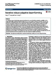
Where In-1 is (n-1)×(n-1) identity matrix and w is a positive constant. It is clear that the term ZTG(x)Θ constitutes the coupling of the unmeasured states Z and the unknown parameters Θ. Suppose that unknown deadzone exists at the actuation of the system given in (1). Such a deadzone behavior can be described by the figure below.
Fig. 1. Deadzone behavior
4 Where u(t) and v(t) are the deadzone output and input respectively. In [10], the authors showed that the deadzone model given in Fig. 1 can be described by a mathematical model that consists of a linear part and a bound. This model can be described as:
u t mv t d v t
(3.a) (3.b)
m is the slope of the deadzone lines. From (3.b), it can be seen that: d v t
(4. a)
Where ρ is the bound of the function d(v(t)) and can be chosen as: ,
(4.b)
Paper Objective: The main objective of this paper is to derive a robust adaptive control law v(t), observer for the unmeasured states Z, and estimator for the unknown parameters Θ such that a global stable performance is achieved and all closed loop signals are guaranteed to be bounded. Since the unknown deadzone contains unknown parameters, then it would be necessary to take those parameters into consideration and design suitable estimators for them. However, the following assumptions need to be achieved so that the suggested control schemes can be realized.
A1: The deadzone output u(t) is not available for measurement. The slopes of the deadzone in both positive and negative directions are the same and equal to m. The deadzone parameters m., br and bl are unknown but their signs are assumed to be known, i.e.
0,
0, and
0.
A2: The parameters of the deadzone are assumed to be bounded i.e. m ∈[mmin, mmax] and
A3: The pair (M, h) is controllable. There exists a diagonal positive definite matrix PZ
BT(x)PZ+PZB(x)≤-QZ for all x
Rn,
∈[bmin, bmax].
Rmxm
such that
where Qz is a positive semi-definite matrix. Also, for every bounded x(t), the
solution of Z(t) is bounded for any initial condition Z(t0).
A4: The sign of each parameter, Θi, i=1: q, in the parameter vector Θ is known and Θi is bounded.
A5: The functions f(x), G(x), a(x), and B(x) are bounded functions of x.
A6: The desired trajectory, xd= xd , x d ,..., xd
( n 1)
is continuous, bounded and available for measurement.
Remarks: 1. For assumption A1, it is practical in many systems that may face deadzone at their actuations since if the deadzone output u(t) is known then the problem would be trivial. Regarding the rest of assumption A1, i.e. the equality of slope m for positive and negative portions of v(t) and also the equality of the parameters br and bl, it is generally adopted in the literature ( see [4, 10] and the references therein).
5 2. For assumption A2, it is satisfied for many physical systems. 3. Assumption A3 can guarantee the existence of a feedback control vector
∈
that can stabilize the linear part of (1), i.e.
there exists a symmetric positive definite matrix P that can satisfy the Lyapunov equation
,
where Q is a symmetric positive definite matrix. For the rest of assumption A3, i.e. the existence of the inequality
BT(x)PZ+PZB(x)≤-QZ, it is required to guarantee that Z(t) has stable behavior provided that x(t) is bounded. 4. Assumption A4 is the only knowledge required for the system to be controlled and it is available for many practical applications. 3.
MAIN RESULTS
Let us define Φ=1/m, and Ψ= ΦΘ. Then, instead of estimating m and Θ, Φ and Ψ will be estimated and considered in the control schemes derived throughout the present paper. Suppose that the system tracking error is: (5) Define the filtered tracking error: n1
d s (t ) ~ x (t ) dt
where
(6)
0 . (6) can be rewritten as s(t)=ΛT
with ΛT=[λn-1, (n-1) λn-2,…,1].
Define Tv [0, n 1 , ( n 1)n 2 , , ( n 1) ] , from (1), (3) and (6) it can be easily verified that: Λ
Λ
Θ
Θ
(7)
Note: It has been shown that the filtered error described by (6) has the following properties: (i) the equation s(t)=0 defines the time-varying hyperplane in Rn, on which the tracking error vector
s(t ) with constant , then then
Ωε
decays exponentially to zero, (ii) if
~ x (t ) i 1 i n ~ 2 , i 1,..., n for t 0 and (iii) if xi
0
0
0 and
0 and
s(t )
will converge to Ωε within a time constant (n-1)/ λ [17, 18].
It is also important to mention that rather than deriving the adaptive laws depending on the filtered error s(t), a tuning error sε, is introduced as follows:
s s s sat Where ε is an arbitrary positive constant and sat(.) is a saturation function defined as:
(8)
6
for c 1 for 1 c 1 for c 1
1 sat c c 1
(9)
At first, it will be assumed that the bounds of the parameters of the deadzone are known. So, it is necessary to add the assumption below in order that the control scheme can be feasible.
A7: The bounds of the deadzone parameters (b and m) are assumed to be known.
It is necessary for both parameters Φ and Ψ to be within predefined given sets, i.e.Φ ∈ Ω Ψ∈Ω
Ψ∈
:Ψ
Ψ
Φ ∈ R: Φ
Φ
Φ , and
Ψ . Φ and Φ are the lower and upper bounds of the set Ω . Ψ and Ψ are the lower and upper
bounds of the set Ω . Theorem 1: Consider that a nonlinear system is described by (1) with its actuation suffers from unknown deadzone behavior described by (3). The system is supposed to satisfy assumptions A3- A6, and the deadzone behavior is assumed to satisfy assumptions A1, A2, and A7. Then the robust adaptive control law given in (10), the unmeasured states observer given in (11), and the unknown parameters estimators given in (12) and (13) guarantee global system stability and that all closed loop signals 2
are bounded and the state vector x(t) converges to Ωε constants, Г= Г-1 R
PxP
,
, PZ is a diagonal positive definite matrix, and k |
Λ
*
1,2, …
for
t t 0 . Where kd, η are positive
/ mmin .
|Ψ
∗
Ψ
(10)
Ψ η| | Φ
(11)
η| |
Φ Φ
Φ and η| |
Φ
Φ
Φ
0
Φ
Φ
η| |
0
(12)
0
Ψ
|
|
Γ
|
|
Γ
Ψ
Ψ and |
|
Γ
0
|
|
Γ
Ψ
Ψ
|
|
Γ
0
Ψ
Ψ
Ψ
Ψ (13)
0 The proof of theorem 1 is explained in Appendix- A-. In (11), the unmeasured states observer contains
Ψ which normally undesirable since it is a discontinuous function.
However, since Ψ= ΦΘ, then from assumptions A1 and A4, the sign of Ψ can be known. Each element of the term
Ψ will
be either 1 or -1 according to the sign of the corresponding element of Ψ which is known. So, the term elements of
Ψ will
be either 1 or -1 and they are invariant with respect to time. It is worth noting that the scheme suggested in theorem 1 relies on
7 the knowledge of the deadzone bounds so that the value of k* would be feasible. The term compensates the term resulted from the deadzone bounds, i.e. Φ
∗
of the suggested controller
. However, it is also important to mention that knowing
the bounds of the deadzone parameters is impractical since it is difficult to know those bounds and specifying the value of k* would be also difficult. In order to overcome the obstacle of knowing the deadzone bounds, assumption A7 is relaxed through deriving another control strategy in which it is not needed to know the bounds of the deadzone parameters. This bounds free strategy depends on the fact that the term Φ
is bounded, i.e. there exists a positive constant
such that:
Φ
(14)
Like the other unknown parameters, an adaptive update law is derived for the parameter and consequently the knowledge of the deadzone bounds is not needed anymore to realize the control scheme. However, it is necessary to guarantee that the estimation of the parameter
wouldn’t leave a predefined set, i.e.
∈ :
∈
. The theorem below explains
the suggested bounds free control strategy.
Theorem 2: Suppose that a nonlinear system described by (1) with its actuation suffers from unknown deadzone behavior described by (3). The system is assumed to satisfy assumptions A3- A6, and the deadzone behavior is supposed to satisfy only assumptions A1, and A2. Then the robust adaptive control law given in (15), the unmeasured states observer given in (16), and the unknown parameters update laws given in (17), (18), and (19) guarantee global system stability and that all closed loop
x(t ) 2 i 1 i n , i 1,..., n for t t 0 . Where kd, η are ~ xi
signals are bounded and the state vector x(t) converges to Ωε positive constants, Г= Г-1 R
PxP
, and PZ is a diagonal positive definite matrix. |
Λ
|Ψ
Ψ
(15)
Ψ η| | Φ
(16)
η| |
Φ Φ
Φ
η| |
Φ
Φ
Φ
0
Φ
Φ
η| |
0
(17)
0
Ψ
|s f |s f
x | x |
sG x Z
Γ
if
sG x Z
Γ
if
Ψ
Ψ
Ψ Ψ or Ψ Ψ |s f x | s G x Z
|s f
x |
sG x Z 0
Γ
if
Ψ
Ψ
|s f
x |
sG x Z
Γ
0
Γ
0
(18)
8 | |
β
| |
β
| |
0
β β
| |
(19)
0
0 The proof of theorem 2 is given in Appendix- B-. 4.
Simulation Results
Consider a single-link mechanical system that suffers from friction torque in its joint and unknown deadzone at its actuation. The system dynamic model can be described as: (20) Where J is the inertia of the link,
is the angular position of the link,
is the actuator output,
is the control input,
and f f is the friction torque that can be described by the following LuGre dynamic friction model: (21) | |
(22) (23)
, 1 , 2 , 3 , Fs , Fc , and s are the friction coefficients. The friction coefficients 1 , 2 and 3 are unknown, while the others, as well as the inertia J, are supposed to be known. The objective is to control the link and make its position and velocity, respectively, to track a predefined trajectory xd and x d respectively.
and
,
Let
, and
. The system described by (20), (21), (22) and (23) can be written into the following form
[19]: Θ
Θ
(24.a) (24.b)
Where: | | Θ
θ θ , θ
1
0 ,
,
0 0
0 | | 0
0 0 ,
,
0
0 0
0 | | 0
0 0 | |
It is clear that, the nonlinear system described by (24) falls in the category of systems addressed throughout the present paper and similar to that of (1). In the present section, the following values for the known parameters will be considered: 3.4,
340,
11,
1.557,
0.14,
5,
10,
0.01
Simulations were carried out for both cases of unknown deadzone, i.e. for the case of unknown deadzone with known and
9 unknown bounds. For the case of unknown deadzone with known bounds, the values of 0.5 and 1.1 are selected as initial values for
and Φ respectively. All other initial values ( ,Ψ, and Z(t)) were set to be zero. The link is controlled to follow a
sinusoidal trajectory, xd (t ) sin0.4t . For realizing the parameters update laws, say (12) and (13), the upper bounds and lower bounds of ΩΦ are chosen to be Φ Ψ
0.04, Ψ
0.2, Ψ
2 and Φ
0.1, and Ψ
0.001. The corresponding bounds of ΩΨ are chosen to be Ψ 0.04. The values of
and
0.2, Ψ
0.1,
were selected to be 0.01 and 5 respectively. For the
deadzone, the following values were used: 0.1,
0.6,
0.7,
0.1,
0.85,
1.25,
∗
2.5
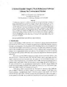
Fig. 2 shows all signals involved in the design when using the approach suggested in theorem 1. In parts A, B, C, and D of Fig. 2, the position tracking performance, position error, velocity tracking performance, and velocity error are shown respectively. Parts E, F, G, H, I, J, K, and L show the plots of the parameter Φ, the filtered error s(t), the unmeasured states
,
, the
unknown parameters Ψ , Ψ , Ψ , and the control action v(t). From Fig. 2 A, B, C, and D, excellent tracking performance can be noticed and the error of both the position and velocity is approaching to a small bound, say Ωε, as the time goes to infinity. As mentioned in section 3, the region Ωε depends on the values of ε and λ. So, if the value of λ is fixed and the value of ε is decreased, then the region Ωε would be decreased and a better tracking would be obtained. But, decreasing the value of ε would cause chattering at the controller which is undesirable. So, choosing the values of ε and λ is a kind of trade-off for having excellent tracking with chattering free controller (for more details see [17, 18]). From Fig. 2 G and H, it is clear that both
and
are bounded which is the result of the boundedness of the observer used in theorem 1 to estimate those unmeasured states. Regarding the unknown parameters Φ, Ψ , Ψ , and Ψ , it is obvious from Fig. 2 parts E, I, J, and K, that their values are remaining within their predefined sets. For the control action shown in Fig. 2 L, it can be seen that, and as mentioned in the proof of theorem1, it is bounded. To have a closer view at the control action v(t), Fig. 3 was plotted that contains two subplots; in part A, zoomed version of the control action v(t) with the deadzone existence is plotted, while in part B the same control action v(t) was sketched but in this time it is assumed that the system doesn’t suffer from deadzone at its actuation. From Fig. 3 A and B, it is clear that the control action with and without deadzone are looked similar except for the sharp edges available for the control action with the deadzone case. Those hard edges are generated to accommodate the deadzone existence at the system actuation during crossing the dead band of the deadzone, that is the band when |
|
| |.
In order to simulate the case of deadzone with unknown bounds that is given in theorem 2, the same parameters and initial values above were used except for the bounds of the deadzone since in this case they are not needed to be known. For the initial value of β, it was set to zero. Fig. 4 shows all signals involved in the design for the case of unknown bounds when using theorem 2. Parts A, B, C, and D of Fig. 4 show the excellent tracking performance of the suggested approach.
10
A
B
2
0.2 x1:Link position xd1:Desired link position
1
Position tracking error 0
0
-0.2
-1
-0.4
-2
0
2
4
6 Time (sec) C
2
8
10
12
x2:Link velocity xd2:Desired link velocity
-0.6
0
2
4
6 Time (sec) D
8
10
12
2 Velocity tracking error 1.5
1
1 0 0.5 -1 -2
0 0
2
4
6 Time (sec) E
8
10
12
1.5
-0.5
0
2
4
6 Time (sec) F
8
10
12
1.5 s:Filtered error
Φ
1
1
0.5 0.5 0 0
0
2
4
6 Time (sec)
8
10
12
-0.5
0
2
4
G
8
10
12
8
10
12
H
0.5
3
0
2
-0.5
1
Z
-1
0
-1.5 -2
6 Time (sec)
-1 0
2
4
6 Time (sec) I
8
10
12
0.02
-2
0
2
4
6 Time (sec) J
0.025 0.02
0.015
Ψ
0.01
Ψ
0.015 0.01
0.005 0
0.005 0
2
4
-3
8
x 10
6 Time (sec) K
8
10
12
0
0
2
4
6 Time (sec) L
8
10
12
10 v(t):The control action with dead zone 5
6
Ψ
4
0 -5
2 0
-10 0
2
4
6 Time (sec)
8
10
12
-15
0
2
4
6 Time (sec)
8
10
12
Fig. 2 A- x1 and xd1. B- Position tracking error. C- x2 and xd2. D- Velocity tracking error. E- The parameter . F- The filtered error (s(t)). G- The unmeasured state . H- The unmeasured states . I- The parameter . J- The parameter . K- The parameter . L- The control action with dead zone existence.
11 -A10 v(t):The control action with dead zone
5
0
-5
-10
-15
0
2
4
6 Time (sec)
8
10
12
-B10 v(t):The control action without dead zone
5
0
-5
-10
-15
0
2
4
6 Time (sec)
8
10
12
Fig. 3 A- The control action v(t) with deadzone. B- The control action v(t) without deadzone.
Both filtered and modified filtered errors are shown in parts E and F respectively and both of them are bounded. Parts G, H, K, L, and M of Fig. 4 show the estimation of the parameters Φ, β, Ψ , Ψ , and Ψ respectively and it is clear that all of them are
12 within their predefined allowable sets of ΩΦ, Ωβ, ΩΨ respectively. Parts I and J of Fig. 4 show the graph of Z and Z respectively, and it is clear that both of them are bounded as it is shown in Appendix- B-. Part N of Fig. 3 shows the graph of the control action v(t) and it is clear that it is also bounded. In order to get a better view of the control action with and without deadzone when using theorem 2, zoomed version of the control action for both with and without deadzone were plotted in Fig. 5 parts A and B respectively. From the graphs shown in Fig. 5, it is clear that both of the cases with and without deadzone are highly similar, and this is majorly because of the control action used in (15) in which the term existence of the deadzone term Φd(v(t)). The term better compensation than that of theorem 1, i.e.
∗
is compensating for the
along with the parameters update law given in (19) provides a , and this fact can be verified when reviewing the graphs of the control
action with and without deadzone shown in Fig. 3 and 5 respectively. It can be easily seen that the similarity between Fig. 5 A and B is higher than that of Fig. 3 A and B which reflects the higher deadzone accommodation with theorem 2. Furthermore, for Fig. 2 F and after t=0.5 sec, the value of the filtered error start to swing around the zero value with a relatively low frequency and it barely reaches the value of 0.01 which is the selected value of . The term
∗
of (10), would also swing around the
zero value with the same frequency of s but with higher amplitude and this swinging would not add a significant oscillation to the overall control action suggested in theorem 1. Conversely, the term
of (15) oscillates around the zero value with a
higher frequency in certain periods of time. This oscillation is caused from the sign function and the relative high frequency oscillation of
around zero. Fig. 6 is a zoomed version of the signal
for the period 4-5 sec (other oscillations available in
other periods of time, but we took this period for explanation). During this period, it can be easily seen that
is oscillating
around zero with a relatively high frequency causing the sign function to result 1 or -1 values with the same oscillation which adds oscillations and spikes to the overall control action as can be seen from Fig. 5. So, comparing Fig. 3 and Fig. 5, the oscillation available in the control action of theorem 1 is less than that of theorem 2. However, the oscillation of the controller in theorem 2 is not of significant amplitude. Furthermore, this oscillation is not affecting the system stability and performance. For Fig. 2 parts I, J, and K, it is clear that the parameters Ψ ,Ψ , and Ψ has increased pragmatically and reached a final value within their set ΩΨ and remained within ΩΨ forever. Such a pragmatic increment reflects their ramping behavior that has been avoided by using the projection algorithm in their adaptive update laws. Similarly for the parameters estimation of Fig 4. parts H, K, L, and M, the use of the projection algorithm made them to be within their allowable sets and don’t ramp out.
13
A 2
x1:Link position xd1:Desired link position
0
-2
B 0.5 Position tracking error 0
0
2
4
6 Time (sec) C
2
8
10
12
x2:Link velocity xd2:Desired link velocity
-0.5
0
2
4
6 Time (sec) D
8
10
12
2 Velocity tracking error 1
0 0 -2
0
2
4
6 Time (sec) E
8
10
12
2
-1
0
2
4
6 Time (sec) F
8
10
12
2 s:Filtered error
sε: Modified filtered error
1
1
0
0
-1
-1
0
2
4
6 Time (sec) G
8
10
12
1.5
0
2
4
6 Time (sec) H
8
10
12
0.4 Φ
β
1 0.2 0.5 0
0
2
4
6 Time (sec)
8
10
12
0
0
2
4
I 5
0
0
0
2
4
6 Time (sec) K
8
10
12
8
10
12
J
5
-5
6 Time (sec)
8
10
12
0.4
-5
0
2
4
6 Time (sec) L
0.2 Ψ
Ψ
0.2
0
0.1
0
2
4
6 Time (sec) M
8
10
12
0.06
0
0
2
4
6 Time (sec) N
8
10
12
50 v(t):The control action with dead zone
0.04 0.02 0
0
Ψ
0
2
4
6 Time (sec)
8
10
12
-50
0
2
4
6 Time (sec)
8
10
12
Fig. 4 A- x1 and xd1. B- Position tracking error. C- x2 and xd2. D- Velocity tracking error. E- The filtered . H- The parameters . I- The error s(t). F- The modified filtered error sε(t). G- The parameter parameter
. J- The parameter
. K- The parameter . L- The parameter N. The control action v(t).
. M- The parameter
.
14 -A30 v(t):The control action with dead zone
20
10
0
-10
-20
-30
-40
0
2
4
6 Time (sec)
8
10
12
-B20 v(t):The control action without dead zone
15
10
5
0
-5
-10
-15
-20 0
2
4
6 Time (sec)
8
10
12
Fig. 5 A- The control action v(t) with deadzone existence. B- The control action v(t) without deadzone.
15
Fig. 6 The oscillation of sε around zero in the period 4- 5 sec.
5.
Conclusion
In this paper, two robust adaptive control strategies were presented for a class of nonlinear systems that contains unknown deadzone characteristics at the system actuation and the coupling of unmeasured states with unknown parameters. In the first approach, the case of unknown deadzone with known parameters bounds was considered and suitable robust adaptive control scheme was suggested and this scheme included the design of observer for the unmeasured states, estimator for the unknown parameters, and robust adaptive control action for the system. It was shown that the suggested control strategy guarantee global system stability and the boundedness of all closed loop signals involved in the design. In the second approach, the case of deadzone with unknown bounds was considered and another robust control strategy was suggested that can guarantee the global system stability and the boundedness of all signals involved. The use of projection algorithm for the estimators of the unknown parameters guaranteed the estimations to be within allowable predefined sets for both approaches. Simulations were carried out for an interesting plant which is a single link mechanical system that suffers from unknown deadzone at its actuation and friction torque, modeled by LuGre friction model, in its joint. For both cases, excellent tracking performance was obtained and all closed loop signals were guaranteed to be bounded. REFERENCES [1]
Tao, G., and Kokotovic, P. V., “Adaptive control of plants with unknown deadzone,” IEEE Trans. Automatic Control, 39, 1994, pp. 59-68.
[2]
Tao, G., and Kokotovic, P. V., “Discrete-time adaptive control of systems with unknown deadzone,” International Journal of Control, 61, 1995, pp. 1- 17.
[3]
Cho, H. Y., and Bai, E. W., “Convergence results for an adaptive deadzone inverse,” International Journal of Adaptive Control and Signal Processing, 12, 1998, pp. 451- 466.
[4]
Lewis, F. L., Tim, W. K., Wang, L. Z., and Li, Z. X., “Deadzone compensation in motion control systems using adaptive fuzzy logic control,” IEEE Trans. Control Systems Technology, 7, 1999, pp. 731- 742.
[5]
Selmic, R. R., and Lewis, F. L., “Deadzone compensation in motion control systems using neural networks,” IEEE Trans. Automatic Control, 45, 2000, pp. 602- 613.
[6]
Zhou, J., Wen, C., and Zhang, Y., “Adaptive output control of nonlinear systems with unknown deadzone,” IEEE Trans. Automatic Control, 51, 2006, pp. 504-511.
16 [7]
Zhou, J., and Shen, X. Z., “Robust adaptive control of nonlinear uncertain plants with unknown deadzone,” IET Control Theory Appl., 1, 2007, pp. 25-32.
[8]
Wang, S. X., Su, C. Y., and Hong, H.Y., “Robust adaptive control of a class of nonlinear systems with unknown deadzone,” Proc. 40th IEEE Conf. on Decision and Control, Orlando, Florida, USA, 2004, pp. 1627- 1632.
[9]
Wang, S. X., Su, C. Y., and Hong, H.Y., “Model reference adaptive control of continuous-time systems with an unknown input deadzone,” IEE Proc. Control Theory Appl., 150, 2003, pp. 261- 266.
[10] Wang, S. X., Su, C. Y., and Hong, H.Y., “Robust adaptive control of a class of nonlinear systems with unknown deadzone,” Automatica, 40, 2004, pp. 407413. [11] Jasim, I. F., “Stable robust adaptive controller and observer design for a class of SISO nonlinear systems with unknown deadzone,” Int. Conf. on Automation and Control, Bali, Indonesia, 2009, pp. 209-215. [12] Jasim, I. F., and Jasim, N. F., “Robust adaptive control of a robotic manipulator with unknown deadzone and friction torques,” Int. Conf. on Computer, Electrical, and Systems Science, and Engineering, Paris- France, 2010, pp. 280- 287. [13] Jasim, I. F., and Jasim, N. F., “ Robust control design for spacecraft attitude systems with unknown deadzone,” 2011 IEEE Int. Conf. on Control Systems, Computing and Engineering, Penang- Malaysia, November 25- 27, 2011. [14] Jasim, I. F., “Robust adaptive controller and observer design for a class of nonlinear systems with unknown backlash-like hysteresis,” Proc. of the 1st Int. Conf. on Energy, Power and Control, Basra- Iraq, Dec 27-31, 2010, pp. 7- 11. [15] Jasim, I. F., and Jasim, N. F., “Adaptive sliding mode control of nonlinear systems with unknown deadzones of unknown bounds,” Proc. of the 1st Int. Conf. on Energy, Power and Control, Basra- Iraq, Dec 27-31, 2010, pp. 7- 11. [16] Jasim, N. F., and Jasim, I. F., “Robust adaptive control of spacecraft attitude systems with unknown deadzones of unknown bounds,” Accepted for publication in Proc. IMechE, Part I, Journal of Systems and Control Engineering. [17] Slotine, J.-J. E., “Sliding controller design for nonlinear systems,” International Journal of Control, 40, 1984, pp. 435-448. [18] Slotine, J.-J. E., and Coetsee, J. A., “Adaptive sliding control synthesis for nonlinear systems,” International Journal of Control, 43, 1986, pp. 1631- 1651. [19] Zhu, Y., and Pagilla, P. R., “Adaptive controller and observer design for a class of nonlinear systems,” Trans. ASME, Journ. Dyn. Syst. Meas. Contr., 128, 2006, pp. 712- 717.
Appendix- A- Proof of theorem 1 Substituting (10) into (7) yields: Λ
|
Λ Θ
Θ
|Ψ
Ψ
∗
(A.1)
Consider the Lyapunov candidate:
Ψ ΓΨ
Φ
Λ|
(A.2)
|
The time derivative of (A.2) can be written as:
Ψ ΓΨ
Φ Φ
Substituting (A.1) into (A.3) yields:
Λ|
|
(A.3)
17
Λ Θ
Θ
|Ψ
|
Λ Ψ ΓΨ
Φ Φ
Λ|
∗
Ψ
(A.4)
|
From (11), it can be easily shown that: Ψ
(A.5)
Using (A.5) and after several mathematical manipulations, the time derivative of the Lyapunov candidate can be expressed as: Φ
|
Ψ Γ
|
∗
Ψ
Φ (A.6)
| |
According to (11) and (12), we have two cases for the adaptive laws of the parameters Ψ and Φ. Case Ψ
1:
|
|
Ψ
Φ
η| |
|
|
Ψ
When
Ψ Γ
Ψ
Ψ
or
0
Φ
and
Φ
Φ
|
Ψ and | Φ
or
Φ and η| |
Γ
0
or 0
Φ
0, then the parameters Ψ and Φ are within their predefined sets and their adaptive rules are and
respectively. Substituting (11) and (12) into (A.6) would result:
∗
Φ
(A.7)
| |
From (8), s(t) can be written as: (A.8) Substituting (A.8) into (A.7) results:
∗
| | 1 2
| |
| | ∗
Φ
∗
Φ
∗
Φ
1 2
| |
∗
Φ
1 2
| |
| |
1 2
Φ | |
1 2
| |
| |
18 (A.9)
| |
Integrating both sides of (A.9) results: 0
| |
Therefore
0
∞
s L2 L , and , Ψ, and Φ ∈ L . Since , Ψ
also bounded. Then using (A.1), it can be easily concluded that
(A.10) Φare bounded and , Ψ, and Φ ∈ L , then , Ψ
s L which implies that s L . Since, s L2 L and
s L , then s 0 as t according to Barbalat's lemma. This would make ∈ L2 L . Since
a positive definite matrix and from (A.5) it can be deduced that ∈ L . Again invoking to Barbalat's lemma, then we have
that
Φ are
converging to Ωε. If
is chosen to be
∈ L , then from (A.10), it can be seen
→ 0 as t .
Case 2: If all conditions of case 1 are not satisfied, then Φ and Ψ are trying to be out of their predefined sets ΩΦ and ΩΨ respectively. According to (12) and (13), the parameters update laws would be Ψ
0, Φ
0. Then the followings comments
can be raised: | |.
C1. It can be easily verified that
C2. From the parameters update laws (12) and (13), it is clear that the parameters update laws are either positive value or zero. The increment of the parameters Φ and Ψ would be always in the positive direction, i.e. Ψ t
1
Ψ t , and similar fact can
be obtained for the parameter Φ. So, the parameters Φ and Ψ can violate their predefined sets only in the upper bounds direction, i.e. Ψ for the parameters vector Ψ and Φ for the parameter Φ. So, the condition of case 1 is not satisfied if and only if Ψ and Φ
Ψ
Φ.
C3. Since the adaptation is stopped for case 2, then according to C1-C3, it can be easily deduced that for case 2 Φ
Φ and
Ψ
Ψ. Then it can be easily concluded that:
Φ
Φ
Φ
0
(A.12)
Ψ
Ψ
Ψ
0
(A.13)
Setting Ψ
0 and Φ
0 for (A.6), then we obtain: |
Φ
|
Ψ
∗
Φ
| |
(A.14)
Using (A.12) and (A.13) into (A.14) along with comments C1 results:
∗
Φ
| |
Similarly to Case 1, and after several mathematical simplifications, (A.15) can be rewritten as:
(A.15)
19 (A.16)
| |
Therefore: 0
| |
Similarly to case 1, s then , Ψ
0
∞
(A.17)
L2 L , and , Ψ, and Φ ∈ L . Due to the fact that , Ψ
Φ are also bounded. Using (A.1), it can be easily shown that
Φ are bounded and , Ψ, and Φ ∈ L ,
s L which implies that s L . Since s
s 0 as t according to Barbalat's lemma. This would make ~ x (t ) converge to . If
L2 L and s L , then
Q Z is chosen to be a positive definite matrix then from (A.5) it can be shown that ∈ L2 L . Since ∈ L , from (A.17), it can be concluded that ∈ L . According to Barbalat's lemma, then → 0 as t .
Appendix- B- Proof of theorem 2 Substituting v(t) of (15) into (7), then the time derivative of the filtered error given in (7) can be written as:
Θ
|Ψ
|
Λ
Λ
Ψ
Θ
(B.1)
Now, consider the Lyapunov candidate:
Ψ ΓΨ
Φ
Λ|
(B.2)
|
Deriving (B.2) with respect to time yields:
Ψ ΓΨ
Φ Φ
Λ|
.
|
(B.3)
Using (B.1) into (B.3) results:
Λ Θ
Θ
Ψ ΓΨ
|Ψ
|
Λ Φ Φ
Λ|
Ψ
.
|
(B.4)
Doing several mathematical manipulations on (B.4), we obtain: Φ
Ψ Γ
|
|
Ψ
Φ
| |
.
(B.5)
From (14), it is clear that Φ Φ
. So, (B.5) can be written as: Ψ Γ
|
|
Ψ
| |
| |
| |
.
20
Φ
Φ
∴
|
Ψ Γ
|
Ψ
|
Ψ Γ
|
Ψ
| |
According to (17) and (18), and (19), there are two cases for the adaptive laws of the parameters Φ , Ψ and Case Ψ Φ
1: Ψ
|
|
η| |
Ψ
Ψ
When
Ψ
Γ
0
β
or β
0 and ,
Φ
and
Φ
| |
are within their predefined sets and their adaptive rules are |
Φ 0 |
|
Ψ and |
Ψ
or
β
or
.
| |
Φ | | and
Φ and η| |
.
| |
(B.6)
respectively. Γ
0
or 0
Φ
0, then the parameters Ψ, Φ, and , and | |respectively
and using those parameters update laws into (B.6) results: ∴
(B.7)
| |
Substituting (8) into (B.7), results: | |
| |
| |
| |
| |
| |
| |
| |
| |
(B.8)
| |
| |
0
0
∞
(B.9)
From (B.9), we can follow similar analysis of case 1 in theorem 1 and it is be easy to prove the stability and boundedness of all signals involved in the suggested design. Case 2: If all conditions of case 1 are not satisfied, then the parameters then the parameters Ψ, Φ, or β are out of their predefined allowable sets ΩΨ, ΩΦ, and Ωβ respectively. Similarly to case 2 of theorem 1, all adaptive laws of Ψ, Φ, or β are positive and according to comment C2, the parameters Ψ, Φ, and β for case 2 are equal to Ψ, Φ, and β respectively. So, it can be easily concluded that:
21 Φ
Φ
Φ
0
(B.10)
Ψ
Ψ
Ψ
0
(B.11)
β
β
β
0
(B.12)
Setting the adaptive laws of Ψ, Φ, and β to zero in (B.6), yields: ∴
Φ
|
|
Ψ
| |
| |
(B.13)
Using (B.10), (B.11), and (B.12) into (B.13), we obtain: ∴
(B.14)
| |
| |
0
0
∞
It is clear that (B.15) and (B.9) are the same. So, similar to case 1, the same stability result can be concluded.
(B.15)