Robust Image Adaptive Steganography using Integer Wavelets
Recommend Documents
Jan 27, 2016 - MM] 27 Jan 2016 ... tives of watermarking are to protect the ownerships of the host images and to preserve their ... been designed so that in addition to perfect reconstruction the filters have in some sense good frequency.
Jan 27, 2016 - ... Communication, Indiana University Purdue University Fort Wayne, IN, ..... [14] V. M. Potdar, S. Han, and E. Chang, âA survey of digital image ...
paper, a new transform domain image steganography technique is presented where Hadamard Transform is performed ..... after converting it from its binary form.
Apr 8, 2016 - Published Online April 2016 in SciRes. http://www.scirp.org/journal/jis ... Host image dimensions will be used to find out the segments which are ... Nilizadeh [3] proposed a novel spatial domain method for steganography in RGB images.
Hence, it improves the performance of the Matlab 2-D de- noising function, which
... Matlab function. Keywords: Discrete Wavelet Transform; Image denoising.
Dec 16, 2002 - explore wavelet denoising of images using several thresholding techniques such as SUREShrink, VisuShrink and BayesShrink. Further, we ...
Jul 4, 2012 - [1] Gustavus J. Simmons, The Prisoners' Problem and ... [3] Scott. Craver, On Public-key Steganography in the. Presence of an Active Warden, ...
Jul 4, 2012 - steganography is Simmons' Prisoners'. Problem. [1].An assumption ...... REFERENCES. [1] Gustavus J. Simmons, The Prisoners' Problem and.
of integer [15]. Therefore, the transform coefficients alteration during an embedding process will produce reconstructed image which is no longer guaranteed to ...
of integer [15]. Therefore, the transform coefficients alteration during an embedding process will produce reconstructed image which is no longer guaranteed to ...
Image Compression Using KLT, Wavelets and an Adaptive Mixture of Principal Components ... image blocks in a block transform coding scheme. The MPC model partitions ..... Acoustics, Speech, and Signal Processing, IEEE, pp. I 609â611,.
Compression, Image, Wavelet, Decomposition level, PSNR. 1. INTRODUCTION ..... [1] R. C. Gonzalez, R. E. woods,âDigital Image processingâ second edition, prentice ... image processingâ. Fourth Edition, Prentice Hall of India private Limited,.
Scholar, 3Asst. Professor, Department of ... is extracted from the cover image using the inverse transformation. .... As we can see in Fig.1, after the first level of ...
30 Aug 2002 - 8. 2 Transformation norm bounds. 11. 2.1 EUCLIDeannormbounds . ... processing in the JPEG File Interchange Format (JFIF) standard of the Joint ... downloaded from ...... pairs with the same lengths (5,3) which give the answer to the ...
Scholar, 3Asst. Professor, Department of Computer Science and Applications, Ch. Devi lal University, Sirsa-. 125055, Haryana (India). 2Department of Computer ...
more curious to get activated and break the encryption keys. ... that human vision system would not be able to detect the hidden information in the image. .... element of mother wavelet matrix,, and the answer should be rounded. .... are usually such
In this paper we have examined ways in which Alice and Bob can practice adaptive ..... of false alarms and misses we see in Table I. fu actual tests conducted b.
(Ed.): Info17nation Hiding. LNCS 1525. pp. ... "Attacks on Steganographic Systems'., in Andreas Pfitzmann (Ed.): Infonnation Hiding. ... M. Goljan and R. Du.
our method image adaptive to embed the watermark into original image so as ... covariance matrices algorithm is used for the extraction of watermark. The.
constraint on the watermark to be embedded into the host. ..... Finally, for a given coding scheme, host pdf and channel, the achievable rate of communication .... It is assumed here that the only free parameter at the encoder is α. Previous.
data with high security, good invisibility and no loss of secret message. ... Steganography is the art and science of concealing information in .... To create a large free space for data hiding, a difference image of an image must be ..... [12]Krenn,
Dec 20, 2016 - Official Full-Text Paper (PDF): Advanced Image Classification using Wavelets and Convolutional Neural Networks. ... (UFLDL) tutorial at Stanford [27]. ..... http://ufldl.stanford.edu/wiki/index.php/Exercise:_Implement_deep_net.
Majid Yaghouti lafarabad, Vahid Kiani, Taha Hamedani, Ahad Harati. Robot Perception Laboratory, Computer Engineering Department. Ferdowsi University of ...
5, we show how to build a statistical model of the subbands. ... To build a complex wavelet transform (CWT), Kingsbury1 has developed a quad-tree algorithm, ...... in Imaging and Electron Physics 111, 1999. 6. ... D. Donoho, âNonlinear solution of
Robust Image Adaptive Steganography using Integer Wavelets
payload in order to ensure lossless recovery. ... have posed serious threats to secure data transmission. This ... and enhanced security against steganalysis.
1
Robust Image Adaptive Steganography using Integer Wavelets K. B. Raja*, S. Sindhu*, T. D. Mahalakshmi*, S. Akshatha*, B. K. Nithin*, M. Sarvajith*, K. R. Venugopal*, L. M. Patnaik** *Department of Computer Science and Engineering University Visvesvaraya College of Engineering, Bangalore University, Bangalore 560 001 ** Microprocessor Applications Laboratory, Indian Institute of Science, Bangalore 560 012 raja [email protected]
Abstract— Information-Theoretic Analysis for Parallel Gaussian Models of Images prescribe embedding the secret data in low and mid frequency regions of image which have large energies. In this paper, we propose a novel steganographic scheme called Robust Image Adaptive Steganography using Integer Wavelet Transform(RIASIWT), which is a practical realization of these prescriptions. Using this scheme we can hide large volumes of data without causing any perceptual degradation of the cover image. The scheme embeds the payload in every non-overlapping 4x4 blocks of the low frequency band of cover image, two pixels at a time, one on either sides of the principal diagonal. Tests for the similarity between the Condition Number of the cover image and the stego image are done for further embedding. We also perform cover image adjustment before embedding the payload in order to ensure lossless recovery. Embedding done in the low frequency bands ensures robustness against attacks such as compression and filtering. Experimental results show better trade off between Visual perceptivity and capacity compared to the existing algorithms. Index Terms— Steganography, Integer Wavelet Transforms, Wavelet Lifting, Cover Image Adjustment.
I. I NTRODUCTION Advancement in digital communication and networking have posed serious threats to secure data transmission. This has driven significant rise in interest among the computer security researchers in the field of information hiding. The early approach to secure communications was via data encryption termed as Cryptography. Cryptography concentrates on designing methods to map the original data to some random looking data (encryption) and at the receiver side recovering the meaningful data (decryption). Information hiding encompasses applications such as Steganography, Copyright protection for digital media and Data embedding . Steganography is the art and science of hiding information into a host data set such that its presence cannot be detected. Generally, steganographic technique consists of two steps: (a) Identification of redundant information in cover object. (b) Replacing or altering the redundant bits to hide the secret message. The redundant bits are chosen for the embedding process because, any changes made in these bits do not corrupt the quality or integrity of the cover object. Steganography finds extensive applications in covert communications, authentication, proof of ownership, customer tracing, feature tagging and data embedding.
Many techniques have been devised to hide information such that the changes made to the cover image are imperceptible to human vision. Common approaches include: (a) Least Significant Bit insertion, (b) Masking and Filtering, (c) Transform techniques. The simplest method for hiding a secret image is modifying the least significant bits of the pixels in the host image. The advantage of this method is its simplicity but it is very weak in resisting even simple attacks such as transforms, compression, etc. The masking and filtering techniques analyze the image and hide information in significant areas so that the hidden message is more a part of the image than being added noise in the image. The transform technique involves modulating the coefficients of the cover data in the frequency domain. Image hiding techniques that are implemented in frequency domain take advantage of features in human visual system for image hiding. Common wavelet transforms often have floating point coefficients. Thus, when the input data consists of sequence of integers (as in case of image), the resulting filtered output no longer consists of integers, which does not allow perfect reconstruction of the original image. As a result, the inverse wavelet transform becomes lossy. However, with the introduction of Wavelet Transforms that map Integers to Integers(IWT), the output can be completely characterized by integers and exact decompression of the original data is achieved. Contribution: In this paper, we propose a novel image adaptive steganographic technique in the integer wavelet transform domain called as the Robust Image Adaptive Steganography using Integer Wavelet Transform (RIASIWT). According to Information-Theoretic Prescriptions for Parallel Gaussian models of images, data should be hidden in low and mid frequency ranges of the host image, which have large energies. However, we find that in order to hide large volumes of data with low perceptual distortion, it is essential to add local perceptual criteria regarding which host coefficients to hide data in. A scheme for making such decision using condition numbers is provided. We also use cover adjustment to prevent the over/under flow of the pixel values after embedding the secret data. The rest of the paper is organized as follows. In section II, we discuss about the related work, In section III we
2
discuss about Background work, In section IV we present the RIASIWT model. The experimental results are presented in section V and concluded in section VI.
II. RELATED WORKS A brief description of related works is presented in this section. Xinpeng Zhang et.al., [1] proposed a coding method for digital steganography in which the amount of bit alterations introduced is significantly reduced, leading to lower distortion and enhanced security against steganalysis. This method works in a running manner thereby representing the secret bits by a series of consecutive cover bits. Flipping of one cover bit is used to insert several secret bits. However, as each cover bit alteration is used to embed several consecutive secret bits, the channel noise is fatal for secret data extraction because any cover bit error will cause several bit errors in the extracted data. Yu-Chee Tseng [2] proposes a scheme that can make the hiding effect quite invisible by taking into account the quality of the image after hiding. It ensures that any bit that is modified in the host image is adjacent to another bit that has the same value as former’s new value. Thus, the existence of secret information in the host image is difficult to detect. Though the scheme is achieved by sacrificing some data hiding space, it offers a good data hiding ratio. Ziang Liang [3] proposes a wavelet domain steganographic algorithm based on redundancy evaluation, named as RES, for the JPEG2000 baseline system. The compatibility and reversibility is ensured by considering the process of uniform quantization and rate distortion optimized truncation. Embedding point and its intensity is adjusted image adaptively to enlarge the information hiding volume. However, the method is limited to lazy mode coding, because of the compatibility with the entropy coder of JPEG2000. The technique works well only with images with uneven brightness and diverse texture activity. Seki et.al., [4] developed an oblivious image steganographic scheme that requires no knowledge on data hiding positions when the data is extracted. This scheme offers to the users, the flexibility of choosing positions to hide data. It modifies the coefficients to embed data image adaptively using compression technology. Since it hides integer data in the transformed coefficients after the quantization process of image compression, the hidden data is no longer distorted by the rest of the compression process. Niansheng Liu et.al., [5] developed a new image hiding scheme based on a chaotic sequence. Chaotic sequences generated by chebyshev maps have good auto correlation and noise like properties. When multiple information is hidden in a digital image, every chaotic sequence is multiplied by a
corresponding digital signal of hidden grey image to obtain a spreading signal. The spreading signal is just a noise like signal to an illegal user who does not know the chaotic sequence. So, he cannot extract the hidden information. The spreading signal is added to the transform spectrum of the original cover image based on discrete space-time transforms. III. BACKGROUND A. Lifting and Integer Wavelet Transform Lifting is a flexible technique that has been used in several different settings for an easy construction and implementation of traditional wavelets and of second generation wavelets, such as spherical wavelets. Since we can write every wavelet transform using lifting, it follows that we can build an integer version of every wavelet transform. In each lifting step we can round-off the result of the filter right before addition or subtraction [6] [7]. An integer dual lifting step thus becomes: X (i) (i−1) (i) (i−1) d1,l = d1,l − b pk s1,l−k + 1/2c (1) k
while an integer primal lifting step is given by X (i) (i) (i) (i−1) uk s1,l−k + 1/2c. s1,l = s1,l − b
(2)
k
This obviously results in an integer to integer transform. Because it is written using lifting steps, it is invertible and the inverse immediately follows by flipping the signs and reversing the operations. This leads to the following pseudo-code implementation of an invertible integer wavelet transform using lifting:
s1,l = s0,2l
(3)
(0)
(4)
(0)
d1,l = s0,2l+1 for i=1 to M (i)
(i−1)
∀l : d1,l = d1,l
(i) (i−1)
(5)
(i) (i)
(6)
X
pk s1,l−k + 1/2c
X
uk d1,l−k + 1/2c
−b
k
(i)
(i−1)
∀l : s1,l = s1,l
−b
k
The inverse transform is given by: for i=M to 1 X (i) (i) (i−1) (i) ∀l : s1,l = s1,l − b uk d1,l−k + 1/2c
(7)
k
(i−1)
∀l : d1,l
(i)
= d1,l − b
X
pk s1,l−k + 1/2c
(8)
(0)
(9)
(i) (i−1)
k
s0,2l+1 = d1,l (0)
s0,2l = s1,l
(10)
Now we rewrite the Haar transform using lifting. First we compute the difference and then use the difference in the second step to compute the average: d1,l = s0,2l+1 − s0,2l
(11)
3
s1,l = s0,2l + d1,l /2
(12)
This is same as Haar transform because s0,2l + d1,l /2 = s0,2l + s0,2l+1 /2 − s0,2l /2 = s0,2l /2 + s0,2l+1 /2 It is now clear that the inverse transform can be computed in two sequential steps. First, recover the even sample from the average and difference, and later recover the odd sample using the even and difference. The equation can be found by reversing the order and changing the signs of the forward transform:
s0,2l = s1,l − d1,l /2
(13)
s0,2l+1 = d1,l + s0,2l
(14)
as long as the transform is written using lifting, the inverse transform can be found immediately.
C. Cover Image Adjustment Before embedding the secret image into the cover image, it is necessary to apply a pre-processing step on the cover image to preserve the overall invertibility of the transform. The embedding process may modify a coefficient that corresponds to a saturated pixel color component in such a way that it may exceed its maximum value (255). In such a case, the higher values will be clipped and the secret message is lost. Hence, the original cover pixel components (C(i, j, k)) are adjusted according to the equations given below,
(19) where C 0 (i, j, k)denotes the modified pixel component, i, j denote the spatial coordinates of the pixel and k represents the specific color component(red, blue, green). The value of N denotes the number of bits to be embedded in each coefficient. Here, N =4.
B. Condition Number The Condition Number matrix for variation in its C. c1,1 c2,1 C = c3,1 c4,1
is a measure of sensitivity of a elements. Consider a 4x4 matrix, c1,2 c2,2 c3,2 c4,2
c1,3 c2,3 c3,3 c4,3
c1,4 c2,4 c3,4 c4,4
In this section we discuss the embedding and extraction module of the RIASIWT algorithm. A. RIASIWT Scheme The data hiding technique employed in RIASIWT is an attempt to hide information without introducing much statistical variations in the image.
The Condition Number of this matrix is evaluated as, κ(C) =k C kk C −1 k
IV. MODEL
(15)
where, C −1 is the inverse of the matrix C Different types of matrix norms are available. A few of them are given below. a)P Norms: n m X X p 1 | Ci,j | ) p k C kp = ( (16) i=1 j=1
Theorem: Embedding in the principal diagonal causes large variation in the condition number. P roof : Consider a non-singular 4x4 matrix A. a1,1 a1,2 a1,3 a1,4 a2,1 a2,2 a2,3 a2,4 A= a3,1 a3,2 a3,3 a3,4 a4,1 a4,2 a4,3 a4,4
Let κ(A) be the Condition Number of the matrix A, then by definition we have,
b)Frobenious Norms: 1
k C kF = T r(CC ∗ ) 2
(17)
κ(A) =k A kk A−1 k
(20)
But from Equation(17), we have, c)Spectral Norms: 1 k C k= (λmax CC ∗ ) 2
1
k A k= T r(AAT ) 2 (18)
where, C ∗ is the transpose of the complex conjugate of C. But in our case, the elements of the matrices are not complex quantities. Hence, C ∗ can be written as C T .
Let AAT = T. Therefore, k A k=
4 X i=1
Similarly,
(21)
1 2
Ti,i
(22)
4
A(1,1) A(2,1)
A(1,2) A(2,2)
A(1,3) A(2,3)
where, each element of D is given as,
A(1,4) A(2,4)
Ai,j
Fig. 1.
A(3,1)
A(3,2)
A(3,3)
A(3,4)
A(4,1)
A(4,2)
A(4,3)
A(4,4)
κ(A) =
4 X i=1
1 2
Ti,i
4 X
(23)
(24)
i=1
Thus from the above equation, it can be seen that condition number is a direct function of the product of traces of the matrices. Hence embedding is not carried out in the principal diagonal.
B. Embedding Module The block diagram for RIASIWT embedding scheme is shown in Figure 2. The payload is converted into one dimensional bit-stream. Before taking transform of the cover image, we perform cover image adjustment on it to assure that the reconstructed pixels of cover image after embedding would not exceed the maximum value (255), thereby, ensuring proper recovery of the secret message. However, as the cover image is in true color format (i.e., it consists of three planes namely Red, Blue and Green), transform is applied on each plane separately. Taking Integer Wavelet Transform instead of Discrete Wavelet Transform ensures lossless coding. The approximation band, P, obtained after applying IWT on the cover image, C, is divided into a number of non-overlapping blocks of size 4x4. Each of these 4x4 blocks become the entries of another matrix, D. If a cover image, C, of size 512x512 is taken , after applying transformation, the size of the approximation band, P, will be 256x256 and the size of matrix D will be 64x64. Thus, we can write, D = [Ai,j ]
i, j ∈ 1, 2, 3, ..., 64
a4i−3,4j−2 a4i−2,4j−2 a4i−1,4j−2 a4i,4j−2
Ai,j = [ak,l ]
1 2
0 Ti,i
a4i−3,4j−3 a4i−2,4j−3 = a4i−1,4j−3 a4i,4j−3
a4i−3,4j−1 a4i−2,4j−1 a4i−1,4j−1 a4i,4j−1
or,
Order in which embedding is done in each 4x4 matrix
k A−1 k= T r(A−1 (A−1 )T )
(25)
k, l ∈ 1, 2, 3, 4
a4i−3,4j a4i−2,4j a4i−1,4j a4i,4j (26)
The payload is embedded in each of these 4x4 matrices, sparing the principal diagonal elements, as it is observed that embedding in the principal diagonal would cause large variations in the Condition Number. After embedding in every two pixels, one on either sides of the principal diagonal, we check the Condition Number of the matrix. This value is compared with the Condition Number of the original matrix. Two different cases arise here, Case1: If the percentage change between the Condition Number of matrix before embedding and the Condition Number of same matrix after embedding in two pixels (a(1,4) and a(4,1) ), does not exceed the predefined threshold, then the the embedding is continued in the next two pixels in the order shown in Figure 1 . Case2: If the Condition Number of the matrix after embedding exceeds the Condition Number of original matrix, then the embedding is stopped. The two changed pixels are replaced by there original values. Also, the total number of pixels embedded in the matrix are recorded in position memory. Let the embedded 4x4 matrix be, A0 = A ± β
(27)
where β is the variation caused by embedding process and is given as, 0 α1,2 α1,3 α1,4 α2,1 0 α2,3 α2,4 β= α3,1 α3,2 0 α3,4 α4,1 α4,2 α4,3 0 Observe that the principal diagonal is all zeros as no change is introduced in it. Let, D1 be the 64x64 matrix of the stego image given by, 0 A1,1 A01,2 · · · A01,64 A02,1 A02,2 · · · A02,64 · · · · · · D1 = · · · · · · · · · · · · A064,1 A064,2 · · · A064,64 or,
D1 = [A0i,j ]
(28)
5
where, i, j ∈ 1, 2, ...., 64 and each A0i,j , is the 4x4 embedded matrix. Substituting for each A0i,j from Equation (27) in Equation (28), we get, A1,1 A1,2 · · · A1,64 A2,1 A2,2 · · · A2,64 · · · · · · D1 = · · · · · · · · · · · · A64,1 A64,2 · · · A64,64 β1,1 β1,2 · · · β1,64 β2,1 β2,2 · · · β2,64 · · · · · · ± · · · · · · · · · · · · β64,1 β64,2 · · · β64,64 where γ is the 64x64 matrix in which each element is the changed 4x4 matrix, βi,j and is given as, β1,1 β1,2 · · · β1,64 β2,1 β2,2 · · · β2,64 · · · · · · γ= · · · · · · · · · · · · β64,1 β64,2 · · · β64,64 (30)
κ(D1 ) =k D1 kk D1−1 k
Substituting Equation (29) in Equation (30), we get,
Taking p=2 in Equation (16) and using it to expand, k (D ± γ) k in Equation (31),
1
| Ai,j ± βi,j |2 } 2 ]
(32)
i=1 j=1
or, k (D ± γ) k= [{
64 X 64 X
1
| [ak,l ]i,j ± [αk,l ]i,j |2 } 2 ]
(33)
i=1 j=1
Similarly for k (D ± γ)−1 k in Equation(31),
k (D ± γ)−1 k= [{
64 X 64 X i=1 j=1
64 X 64 X
| ([ak,l ]i,j ±[αk,l ]i,j )−1 |2 } 2 ] (35) 1
i=1 j=1
Only those matrices in which αk,l ak,l are chosen for embedding. This is justified as the above condition will ensure that the Eigen Value of the embedded matrix will not vary significantly, thus not varying the Condition Number significantly as stated in T heorem. Substituting the above condition in Equations (33) and (35),we get, k (D ± γ) k≈ [{
64 64 X X
1
| [ak,l ]i,j |2 } 2 ]
(36)
i=1 j=1
k (D ± γ)−1 k≈ [{
64 X 64 X
1
| ([ak,l ]i,j )−1 |2 } 2 ]
(37)
i=1 j=1
thus we get, k (D ± γ) k≈k D k
(38)
k (D ± γ)−1 k≈k D−1 k
(39)
and
Substituting Equations (38) and (39) in (31), κ(D1 ) ≈k (D) kk (D)−1 k
(40)
κ(D1 ) ≈ κ(D)
(41)
(31)
κ(D1 ) =k (D ± γ) kk (D ± γ)−1 k
64 X 64 X
k (D±γ)−1 k= [{
(29)
D1 = D ± γ
k (D ± γ) k= [{
or,
Thus the Condition Number of the stego image is approximately same as the Condition Number of the cover image, so that not much variation occurs in the stego image. This ensures that the statistical features of the cover image are not altered significantly. The position memory is embedded continuously into the approximation band of another color plane. For added security we use pseudo-random number generator to randomly select the blocks. Thus, even if the algorithm is known, one cannot extract the hidden data without knowing the key used for pseudo-random number generator. Inverse IWT is taken after embedding is completed to obtain stego image.
C. Extraction Module
1
| (Ai,j ± βi,j )−1 |2 } 2 ]
(34)
The extraction process is quite simple and the inverse of the embedding operation. Figure 3 shows the block diagram for extraction of payload from the cover image. The stego image is separated into different color planes and IWT is performed
6
TABLE I
Cover Image N=4
Algorithm for Embedding: RIASIWT 1) Take a color image of size 512x512 as an input and perform cover image adjustment. 2) Separate the color planes. 3) Take IWT of one of the color planes. 4) Divide the approximation band into non-overlapping matrices of size 4x4. 5) Find the Condition Number of each matrix. 6) Embed two pixels of payload in two non-principal diagonal elements of 4x4 matrix, one on either side of the principal diagonal. 7) Check the Condition Number of altered matrix. 8) If the percentage change between the Condition Number of original matrix obtained in step 5 and that of the changed matrix obtained in step 7 is within the threshold, repeat step 6 and step 7, else switch to step 9. 9) Repeat step 5 to step 8 for each 4x4 matrix and record the number of pixels embedded in each matrix into an array (position memory). 10) Embed the array obtained in step 9 into the approximation band of another color plane of the cover image. 11) Take the inverse transform using IIWT. 12) Combine the three color planes into a single color image.
Cover Adjustment
Color Plane Separation
Haar
Key
Lifting
Integer Wavelet Transform
Pseudo Random Number Generator
Extraction of 4x4 Blocks from Approximation Band
Position Memorization
Embedding Based on
Embed in Approximation band
Payload One Dimensional Bit Stream
RIASIWT
Inverse Integer Wavelet Transform Stego Image
Fig. 2. Block Diagram for Embedding the Payload in Cover Image using RIASIWT algorithm
D. Algorithm Stego Image
Problem definition: Consider a cover image and a payload, the objectives are to
Separation of Colour Planes Haar
Lifting
Pseudo Random Number Generator Key
Integer Wavelet Transform 4x4 blocks of Approximation Band
Approximation Band
Position Memory
•
Embed the payload into the cover image using Integer Wavelet Transform.
•
The stego image should be robust and secure against attacks.
•
The stego image must have minimum perceptual degradation i.e., maximum PSNR.
Retrieval Using RIASIWT One−Dimensional bit stream of Payload Payload
Assumptions: •
Fig. 3. Block diagram for Retrieval of Payload from Stego Image using RIASIWT algorithm
•
•
on each plane. From the approximation band, the position memory is retrieved and later from another approximation band, the payload is retrieved by making use of the position memory. However, it is necessary that the decoder knows in which plane the position memory and payload are embedded. The key for the pseudo-random number generator must also be known, without which, the retrieved message is just a random noise for the retriever. The necessity of knowledge of the order in which the pixels are embedded adds to the extra security of the stego image. Thus, even if the algorithm is made public, it is not possible to retrieve the data without knowing the key and the embedding order.
Embedding is carried out only in the non-singular matricies. A change in the intensity value of the pixel by ±15 or less is imperceptible to human vision. Cover image and Payload are JPEG images. The Cover image is a color image of size 512x512.
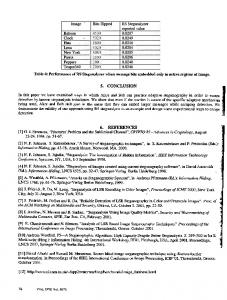
The RIASIWT algorithm for embedding is given in Table I. Cover image is adjusted against overflow and converted into wavelet domain using IWT. The payload is converted into one dimensional bit stream and embedded in 4x4 non overlapping blocks of approximation band of the cover image to derive the stego data. The stego data is converted into spatial domain stego-image using Inverse IWT. The RIASIWT algorithm for retrieval is given in Table II. The payload is retrieved at the destination using the reverse process of RIASIWT embedding.
7
TABLE II
Algorithm for retrieval: RIASIWT 1) Input stego image and separate the color planes. 2) Apply Integer Wavelet Transform. 3) Retrieve the position memory from the approximation band of corresponding color plane. 4) Divide the approximation band into non-overlapping matrices of size 4x4. 5) Start extracting the payload in the order in which it is embedded. Use position memory to know the exact number of pixels embedded in each matrix. 6) Convert the extracted one dimensional array of payload into an image.
Fig. 6.
Stego image(Flowers) and Retrieved payload(Parrots)
Fig. 7. Stego images generated by RIASIWT algorithm for different thresholds,T =0, 15, 30, 50 Fig. 4. Test Image Set: Bouquet, Lena, Flowers, Mandril, Mountain, Red parrot, Pepper, Saturn, Tigers
17 Pepper Mandril
16
Capacity in 1000 Pixels
15 14 13 12 11 10 9 8
Fig. 5.
Cover image(Flowers) and Original payload(Parrots)
0
10
20 30 Threshold
40
50
Fig. 8. Relationship of the Capacity versus the threshold obtained for high resolution(Pepper) and low resolution (Mandril) image.
8
Payload Size (in pixels) 128x128 150x150 200x200 256x256
DWT PSNR 44.51 43.91 42.53 41.10
DWT MSE 2.29 2.64 3.62 5.04
IWT PSNR 45.03 44.34 42.85 41.32
IWT MSE 2.04 2.38 3.37 4.79
TABLE III COMPARISON OF
DWT AND IWT WITH PARROTS AS THE PAYLOAD AND S ATURN (512 X 512) AS COVER IMAGE
TABLE IV E XPERIMENTAL RESULTS : PAYLOAD (PARROTS ), C OVER IMAGE ( FLOWERS )
V. EXPERIMENTAL RESULTS AND PERFORMANCE ANALYSIS We tested our algorithm on a test image set shown in Figure 4, which includes some of the common images used in steganography. The scheme provided excellent results in all the cases. The algorithm was simulated using MATLAB. Figure 5 shows the cover image and payload before embedding. The stego image obtained after embedding the payload using RIASIWT algorithm and the retrieved payload from the stego image are shown in Figure 6. It is observed that the cover image and stego image as well as the original payload and the retrieved payload are similar. We now show that, using the proposed algorithm, one can hide large volumes of data with high robustness and minimal perceptual degradation. We use PSNR as an objective metric to qualify the quality of the stego image. Table IV shows the number of pixels embedded in the cover image for different percentage threshold. It is observed that as the threshold increases, the capacity increases remarkably with slight decrease in PSNR. The entropy variation remains almost zero till the threshold reaches the value, 40. At threshold equal to 40, the entropy variation slightly increases. The MSE values are also acceptable. Figure 7 shows the different stego images obtained after embedding with different thresholds viz. 0, 15, 30 and 50. It is observed that the stego image in all the cases is very similar to the original cover image. However, minute changes can be observed in the low intensity regions of the
stego image for threshold equal to 50. A comparison between IWT and DWT has been made in Table III to show that IWT can perform better and lossless than DWT. It is observed that the PSNR and MSE of the images have improved remarkably after employing IWT. The Graph in Figure 8 shows the comparison between the performance of RIASIWT algorithm on a low resolution image (Mandril) and a high resolution image (Pepper). For low values of threshold, T, the algorithm embeds almost same volume of payload in both the images. However, beyond the threshold 10, there is a significant rise in the payload volume in the low resolution image. It is also observed that at threshold 30, the given payload of size 16,384 pixels gets completely embedded in Mandril whereas Pepper can accommodate only about 12,250 pixels of payload. VI. CONCLUSIONS A robust steganographic technique to embed high volumes of data in the integer wavelet domain has been proposed. The scheme uses the Condition Number of the blocks of the stego image as an objective metric to decide the amount of information to be hidden in the corresponding blocks of cover image. Embedding done in non-principal diagonal coefficients of the low frequency band ensures better robustness. The algorithm offers excellent performance without any error correction codes. It can hide high volumes of information compared to many existing robust and secure data hiding techniques and yet retain better values of PSNR and MSE. However, the algorithm requires hiding of the position memory along with the payload in the stego image which may be a drawback in certain cases. This when avoided can increase the capacity to a higher value. R EFERENCES [1] Xinpeng Zhang, Shuozhong Wang, “Dynamical Running Coding in Digital Steganography,” in IEEE Signal Processsing Letters, vol. 13, pp. 165–168, 2006. [2] Yu-Chee Tseng, “Data Hiding in Two Colour Images,” in IEEE Transactions on Computers, vol. 51, pp. 873–878, 2002. [3] Zhang Liang, “Wavelet Domain Steganography for JPEG 2000,” in IEEE Proceedings of International Conference on Communication,Circuit and System, pp. 40–43, 2006. [4] Yusuke Seki, Hiroyuki Kobayushi, Masaaki Fujiyoshi, Hitoshi Kiya, “Quantization-Based Image Steganography without Data Hiding Position Memorization,” in International Symposium on Circuits and Systems, pp. 4987–4990, 2005. [5] Niansheng Liu, Donghui Guo, Gerard Parr, “A New Image Steganography For Internet Communications based on Chaotic Sequences,” in Proceedings of International Conference on Intelligent Information Hiding and Multimedia, pp. 121–124, 2006. [6] A. R. Calderbank, Ingrid Daubechies, Wim Sweldens, Boon-Lock Yeo, “Wavelet Transforms that Map Integers to Integers,” in Applied and Computational Hormonic Analysis, vol. 5, pp. 332–369, August 1998. [7] Steven Dewitte, Jan Cornelis, “Lossless Integer Wavelet Transform,” in IEEE Signal Processing Letters, vol. 4, pp. 158–160, June 1997.