APPLIED PHYSICS LETTERS 88, 232106 共2006兲
Improvement of resistive memory switching in NiO using IrO2 D. C. Kim,a兲,b兲 M. J. Lee, S. E. Ahn, S. Seo, J. C. Park, and I. K. Yoo Samsung Advanced Institute of Technology, Suwon 440-600, Korea
I. G. Baek,a兲,c兲 H. J. Kim, E. K. Yim, J. E. Lee, S. O. Park, H. S. Kim, U-In Chung, J. T. Moon, and B. I. Ryu Process Development Team, Semiconductor R & D Center, Samsung Electronics, Co. Ltd., San No. 24, Nongseo-Ri, Kiheung-Eup, Yongin City, Kyeonggi-Do 449-711, Korea
共Received 13 January 2006; accepted 20 April 2006; published online 6 June 2006兲 For the development of resistive memory devices using NiO, improvements of several memory switching properties are required. In NiO memory cells with noble metal electrodes, broad dispersions of memory switching parameters are generally observed with continuous memory switchings. We report the improvements in minimizing the dispersions of all memory switching parameters using thin IrO2 layers between NiO and electrodes. The role of thin IrO2 layers on NiO growth and memory switching stabilization are discussed. © 2006 American Institute of Physics. 关DOI: 10.1063/1.2210087兴 A resistive switching memory with NiO has been widely investigated for memory device applications due to a number of advantages over other oxide materials.1–4 The memory cell, which consists of insulator and noble metal electrodes, typically has a structure of M-I-M where M and I are Pt and NiO, respectively. Despite its good retention and endurance properties, several problems need to be elucidated before taking into consideration device applications. One of the issues is about minimizing the dispersion of memory switching parameters such as Ron, Roff, Vset, and Vreset. Here, Ron and Roff represent the resistance values of low and high resistance states, and Vset and Vreset are the required voltages for resistive transition from Roff state to Ron state and vice versa.1,2 In fact, as the device is getting stressed from memory switching cycling, one could observe broad dispersions of these parameters. It would cause severe problems in controlling and reading the memory switching states as a result. In this letter, we report one of the ways to minimize the dispersions of memory switching parameters by inserting thin IrO2 layers at M-I interfaces. IrO2 is one of the wellknown conducting oxides. It has been used as a diffusion barrier for the improvement of fatigue properties in ferroelectric memory devices.5 Details on NiO film deposition and measurement setup were described elsewhere.2,3 Dc magnetron sputtering method was used for deposition of IrO2 and Pt electrodes. IrO2 was deposited at temperature of 300 ° C with working pressure of 共Ar+ O2兲 gases at 5 mTorr. Oxygen content in the gas mixture was 30%. X-ray diffraction 共XRD兲 measurement clearly showed IrO2 peaks, which validates the formation of crystalline IrO2. Figure 1 shows representative I-V curves of memory switching with and without thin IrO2 layers at M-I interfaces. The area of memory cells is 30⫻ 30 m2 with 50 nm of NiO layer. The thickness of IrO2 layer is about 5 nm. In order to continuously switch the memory state of samples, an autoa兲
Authors to whom correspondence should be addressed. Electronic mail:
[email protected] c兲 Electronic mail:
[email protected] b兲
matic measurement program using dc voltage sweep method was developed and used.2,3 It is clearly noticed that I-V curves with successive memory switchings are greatly stabilized by inserting IrO2 at Pt–NiO interfaces. This result can be reconfirmed by replotting the switching parameters with the switching cycles as shown in Fig. 2. The improvements are especially evident in dispersions of Vset and Roff. Also a “set fail” phenomenon, which is a failure of switching from Roff state to Ron state by applying Vset, observed at times in Pt/ NiO / Pt cells effectively disappears by using IrO2. In Fig. 3 the switching parameters shown in Fig. 2 are replotted in histograms and summarized in Table I. With IrO2 layers standard deviations of all memory switching parameters and average resistance values show large decrease compared to those in NiO memory cell with Pt electrodes only. Especially the average value of Roff decreases more than one order of magnitude. The large leakage current with conducting oxide electrodes has been a well-known issue in ferroelectric memory devices. It has been attributed to the absence of a potential barrier at the interfaces due to its low work function compared to noble metals.6 However, NiO is a well-known Ni-deficient p-type semiconductor and it would form a Schottky barrier with low work function materials such as IrO2. It could result in increased values of memory switching parameters or an ab-
FIG. 1. Memory switching I-V curves in Pt/ NiO / Pt 共left figure兲 and Pr/ IrO2 / NiO / IrO2 / Pt 共right figure兲 memory cells. The data are from continuous memory switchings of 200 times. The gray lines are the reset transition curves from Ron state to Roff state by sweeping the voltage form zero to V 艌 Vreset whereas the black lines are the set transition curves from Roff state to Ron state by sweeping the voltage from zero to Vset.
0003-6951/2006/88共23兲/232106/3/$23.00 88, 232106-1 © 2006 American Institute of Physics Downloaded 06 Jun 2006 to 202.20.193.170. Redistribution subject to AIP license or copyright, see http://apl.aip.org/apl/copyright.jsp
232106-2
Kim et al.
Appl. Phys. Lett. 88, 232106 共2006兲 TABLE I. Summary on variation of memory switching parameters with the switching cycles shown in Fig. 2. Avg. 共Std.兲 represents an average value 共standard deviation兲 of the parameter. Vreset 共V兲 Ron 共⍀兲 Vset 共V兲 Avg. 共Std.兲 Avg. 共Std.兲 Avg. 共Std.兲
Roff 共⍀兲 Avg. 共Std.兲
Pt/ NiO / Pt 1.65 共0.61兲 0.56 共0.16兲 173 共126兲 392 k 共317 k兲 14.4 k 共1.8 k兲 Pt/ IrO2 / NiO / IrO2 / Pt 1.43 共0.16兲 0.41 共0.03兲 100 共23兲
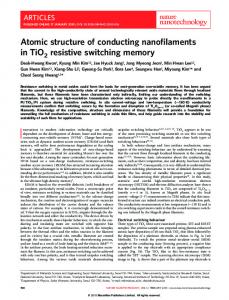
FIG. 2. Variation of the memory switching parameters with respect to switching cycles in Pt/ NiO / Pt 共unfilled兲 and Pr/ IrO2 / NiO / IrO2 / Pt 共filled兲 memory cells. In the left figure triangle 共square兲 symbols represent Vset 共Vreset兲 data. In the right figure triangle 共square兲 symbols represent Roff 共Ron兲 data. Ron and Roff are resistances measured at V = 0.2 V in each memory state. The parts encircled by dotted line represent the “set fail” phenomena.
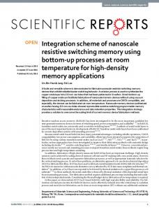
sence of memory switching.7 Actually degradation of memory switching properties with a severe reduction of switching endurance was observed if the IrO2 layer was thicker than 20 nm. This indicates that IrO2 should be used as a thin layer for the improvement in dispersions of memory switching parameters. Considering a significant amount of defects or dopants expected in semiconductorlike oxides, the depletion width in Schottky-barrier formation would become much wider than in doped semiconductors. Interface effects in consideration of work function and thickness of electrodes need further qualification. Physical reasons for memory switching stabilization by IrO2 are investigated. Figure 4 shows the XRD patterns of NiO with and without a thin IrO2 layer on the bottom Pt electrode. The XRD patterns of samples were measured using a grazing incidence mode. An increase of peak intensities more than three times in NiO on IrO2 indicates an enhancement of crystallinity compared with NiO on Pt. This suggests that more crystalline NiO would help the memory switching be more stable. It is consistent with empirical observations that the memory switching would become stable as the NiO crystallinity increases. Figure 5 shows the transmission electron microscopy 共TEM兲 images of NiO with and without IrO2 layers. The microstructures at interfaces look different. Columnar microstructures are observed from bottom to top in NiO deposited on Pt 共left figure兲. In contrast, NiO deposited on IrO2 shows fine microstructures near IrO2. NiO becomes columnar shapes with an increase of grain size as it approaches the top electrode 共right figure兲. The XRD and TEM results show that a thin IrO2 layer does have effects on crystalline structure of NiO. However, it should be mentioned that the TEM images were obtained from pristine NiO
films which did not go through the electroforming process to initiate the memory switching. Recent investigation showed that the memory switching in NiO would be associated with the formation and rupture of localized filamentary conducting paths, and the resistive switching by local filaments with an area size of several tenths of nanometers was directly observed using conducting atomic force microscopy 共C-AFM兲.8,9 In connection with the improved memory switching by IrO2, this suggests that highly crystalline NiO might confine filamentary conducting paths locally much better, avoiding their random formation and rupture for memory switching. Due to the localized nature of filaments it is not an easy task to investigate the relations of NiO microstructures and their evolution with successive memory switchings. Further experiments to study these subjects are ongoing. From the view of filaments, the dispersions of memory switching parameters could be minimized by stabilizing the filament formation and rupture, which might occur at local domains near M-I interfaces. If the filament formation and rupture are associated with oxygen at local domains, the ruptured part of the filament would naturally form high resistance domains via oxidation with the help of high currentinduced local Joule heating. In the opposite case, the conducting filament at local domains would be formed via generation of oxygen-related defects by high electric field with possible assistance of Joule heating effect. One might guess that thin IrO2 layers would help to stabilize local oxygen migrations for filament formation and rupture, thus giving the stable memory switching parameters. Recently microarea Auger electron spectroscopies 共AES兲 were carried out on NiO with electrical stress. Local spot on NiO surface was electrically stressed by a C-AFM tip with a voltage bias
FIG. 3. Histograms of memory switching parameters by replotting the data in Fig. 2. Lines are obtained by fitting to the Gaussian distribution. Due to FIG. 4. XRD data of NiO deposited on Pt and IrO2 / Pt. The inset shows a the “set fail,” parameters from Pt/ NiO / Pt memory cell show overlap of magnified view of 共111兲 and 共200兲 peaks of NiO for comparison. data. Downloaded 06 Jun 2006 to 202.20.193.170. Redistribution subject to AIP license or copyright, see http://apl.aip.org/apl/copyright.jsp
232106-3
Appl. Phys. Lett. 88, 232106 共2006兲
Kim et al.
FIG. 5. TEM images of Pt/ NiO / Pt 共left figure兲 and Pt/ IrO2 / NiO / IrO2 / Pt 共right figure兲 memory cells. In the right figure top Pt electrode and IrO2 was peeled off during the TEM sample preparation. The inset in the right figure shows a magnified view of NiO / IrO2 / Pt interface.
of 10 V for 150 s. The AES depth profiles at the local area 共1 ⫻ 1 m2兲 including the stressed spot showed a significant decrease of oxygen content at interfaces, compared to bare NiO without any electrical stress.10 This suggests that oxygen migrations by electric field and their control would be important to obtain stable memory switching parameters.11 In summary, the broad dispersions of memory switching parameters by continuous memory switchings in NiO with Pt electrodes are greatly minimized by inserting thin IrO2 layers between NiO and Pt. The roles of IrO2 on memory switching are investigated. Compared to NiO deposited on top of Pt, a thin IrO2 layer enhances the crystallinity of NiO on top with fine microstructures at NiO – IrO2 interfaces. Based on a filamentary conduction model where the memory switching is associated with the formation and rupture of filaments at local domains near interfaces, IrO2 can be thought to help stabilize the local oxygen migrations for the filament formation and rupture, thus resulting in more stable memory switching parameters. Further experiments using C-AFM and electric pulses are ongoing to reveal the physical mechanisms of formation and rupture of local filaments in consideration of special roles of oxygen.
1
I. G. Baek, M. S. Lee, S. Seo, M. J. Lee, D. H. Seo, D.-S. Suh, J. C. Park, S. O. Park, H. S. Kim, I. K. Yoo, U-I. Chung, and J. T. Moon, Tech. Dig. - Int. Electron Devices Meet. 2004, 587. 2 S. Seo, M. J. Lee, D. H. Seo, E. J. Jeoung, D.-S. Suh, Y. S. Joung, I. K. Yoo, I. R. Hwang, S. H. Kim, I. S. Byun, J.-S. Kim, J. S. Choi, and B. H. Park, Appl. Phys. Lett. 85, 5655 共2004兲. 3 S. Seo, M. J. Lee, D. H. Seo, E. J. Jeoung, D.-S. Suh, Y. S. Joung, I. K. Yoo, I. R. Hwang, S. H. Kim, I. S. Byun, J.-S. Kim, J. S. Choi, and B. H. Park, Appl. Phys. Lett. 86, 093509 共2005兲. 4 I. G. Baek, D. C. Kim, M. J. Lee, H. J. Kim, M. S. Lee, J. E. Lee, S. E. Ahn, S. Seo, J. H. Lee, J. C. Park, Y. K. Cha, S. O. Park, H. S. Kim, I. K. Yoo, U-I. Chung, and J. T. Moon, Tech. Dig. - Int. Electron Devices Meet. 2005, 769. 5 Takashi Nakamura, Yuichi Nakao, Akira Kamisawa, and Hidemi Takasu, Appl. Phys. Lett. 65, 1522 共1994兲. 6 C. S. Hwang, B. T. Lee, C. S. Kang, J. W. Kim, K. H. Lee, and M. Y. Lee, J. Appl. Phys. 83, 3703 共1998兲. 7 S. Seo, M. J. Lee, D. C. Kim, S. E. Ahn, B.-H. Park, Y. S. Kim, I. K. Yoo, I. S. Byun, I. R. Hwang, S. H. Kim, J.-S. Kim, J. S. Choi, J. H. Lee, S. H. Jeon, S. H. Hong, and B. H. Park, Appl. Phys. Lett. 87, 263507 共2005兲. 8 D. C. Kim, S. Seo, S. E. Ahn, D.-S. Suh, M. J. Lee, B.-H. Park, I. K. Yoo, I. G. Baek, H.-J. Kim, E. K. Yim, J. E. Lee, S. O. Park, H. S. Kim, U-In Chung, J. T. Moon, and B. I. Ryu, Appl. Phys. Lett. 88, 202102 共2006兲. 9 J. B. Yun, S. Seo, D. H. Seo, M. J. Lee, D. C. Kim, S. E. Ahn, B. H. Park, I. K. Yoo, C. Kim, and H. Shin 共unpublished兲. 10 M. Porti, M. Nafria, X. Aymerich, A. Olbrich, and B. Ebersberger, J. Appl. Phys. 91, 2071 共2002兲. 11 R. Fors, S. I. Khartsev, and A. M. Grishin, Phys. Rev. B 71, 045305 共2005兲.
Downloaded 06 Jun 2006 to 202.20.193.170. Redistribution subject to AIP license or copyright, see http://apl.aip.org/apl/copyright.jsp