Rice University. 6100 Main St, Houston, TX 77005. [vivekb, Kaushik.Mitra, vashok] @rice.edu. Abstract. Current light field (LF) cameras provide low spatial res-.
Improving Resolution and Depth-of-Field of Light Field Cameras Using a Hybrid Imaging System Vivek Boominathan, Kaushik Mitra, Ashok Veeraraghavan Rice University 6100 Main St, Houston, TX 77005 [vivekb, Kaushik.Mitra, vashok] @rice.edu
Abstract
1. Introduction Light field (LF) is a 4-D function that measures the spatial and angular variations in the intensity of light [2]. Acquiring light fields provides us with three important capabilities that a traditional camera does not allow: (1) render images with small viewpoint changes, (2) render images with post-capture control of focus and depth-of-field, and (3) compute a depth map or a range image by utilizing either multi-view stereo or depth from focus/defocus methods. The growing popularity of LF cameras is attributed to these three novel capabilities. Nevertheless, current LF cameras suffer from two significant limitations that hamper their widespread appeal and adoption: (1) low spatial resolution and (2) limited DOF control.
Angular Resolution
Current light field (LF) cameras provide low spatial resolution and limited depth-of-field (DOF) control when compared to traditional digital SLR (DSLR) cameras. We show that a hybrid imaging system consisting of a standard LF camera and a high-resolution standard camera enables (a) achieve high-resolution digital refocusing, (b) better DOF control than LF cameras, and (c) render graceful highresolution viewpoint variations, all of which were previously unachievable. We propose a simple patch-based algorithm to super-resolve the low-resolution views of the light field using the high-resolution patches captured using a high-resolution SLR camera. The algorithm does not require the LF camera and the DSLR to be co-located or for any calibration information regarding the two imaging systems. We build an example prototype using a Lytro camera (380 × 380 pixel spatial resolution) and a 18 megapixel (MP) Canon DSLR camera to generate a light field with 11 th MP resolution (9× super-resolution) and about 91 of the DOF of the Lytro camera. We show several experimental results on challenging scenes containing occlusions, specularities and complex non-lambertian materials, demonstrating the effectiveness of our approach.
Hybrid Imager (our system)
Lytro camera
11 megapixels 9 X 9 angular resolution.
0.1 megapixels 9 X 9 angular resolution.
Fundamental resolution trade-off
11 megapixels no angular information.
DSLR camera
Spatial Resolution
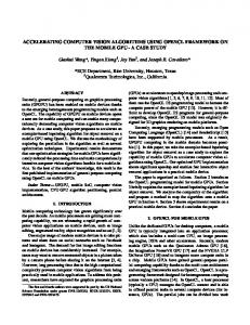
Figure 1: Fundamental resolution trade-off in light-field imaging: Given a fixed resolution sensor there is an inverse relationship between spatial resolution and angular resolution that can be captured. By using a hybrid imaging system containing two sensors, one a high spatial resolution camera and another a light-field camera, one can reconstruct a high resolution light field.
1.1. Motivation Fundamental Resolution Trade-off: Given an image sensor of a fixed resolution, existing methods for capturing light-field trade-off spatial resolution in order to acquire angular resolution (with the exception of the recently proposed mask-based method [26]). Consider an example of a 11 MP image sensor, much like the one used in the Lytro camera [24]. A traditional camera using such a sensor is capable of recording 11 MP images, but acquires no angular information and therefore provides no ability to perform post-capture refocusing. In contrast, the Lytro camera is capable of recording 9 × 9 angular resolution, but has a low spatial resolution of 380 × 380 pixels (since it contains a 9 × 9 pixels per lens array). This resolution loss is not restricted to microlens array-based LF cameras but is a common handicap faced by other LF cameras including traditional mask-based LF cameras [37], camera arrays [31], and angle-sensitive pixels [38]. Thus, there is an imminent need for improving the spatial resolution characteristics of LF sensors. We propose using a hybrid imaging system containing two cameras, one with a high spatial resolution sen-
Near Focused
Far Focused
Depth Map
DSLR Camera (high-resolution image)
Light-field Camera (low-resolution light-field)
+ Hybrid Imaging (high-resolution light-field)
Depth Map
Near Focused
Far Focused
Figure 2: Traditional cameras capture high resolution photographs but provide no post-capture focusing controls. Common light field cameras provide depth maps and post-capture refocusing ability but at very low spatial resolution. Here, we show that a hybrid imaging system comprising of a high-resolution camera and a light-field camera allows us to obtain high-resolution depth maps and post-capture refocusing.
sor and the second being a light-field camera, which can be used to reconstruct a high resolution light field (see Figure 1). Depth Map Resolution: LF cameras enable to computation of depth information by the application of multi-view stereo or depth from focus/defocus methods on the rendered views. Unfortunately, the low spatial resolution of the rendered views result in low resolution depth maps. In addition, since the depth resolution of the depth maps (i.e., the number of distinct depth profiles within a fixed imaging volume) is directly proportional to the disparity between views, the low resolution of the views directly result in very few depth layers in the recovered range map. This results in errors when the depth information is directly used for vision tasks such as segmentation and object/activity recognition. DOF Control: The DOF of an imaging system is inversely proportional to the image resolution (for a fixed f# and sensor size). Since the rendered views in a LF camera are low-resolution, this results in much larger DOF than can be attained using high resolution DSLR cameras with similar sensor size and f#. This is a primary reason why DSLR cameras provide shallower DOF and are favored for photography. There is a need for a high resolution shallow DOF LF imaging device.
1.2. Contributions In this paper, we propose a hybrid imaging system consisting of a high resolution standard camera along with the low-resolution LF camera. This hybrid imaging system (Figure 2) along with the associated algorithms enables us
to capture/render (a) high spatial resolution light field, (b) high spatial resolution depth maps, (c) higher depth resolution (more depth layers), and (d) shallower DOF.
2. Related Work LF capture: Existing LF cameras can be divided into two main categories: (a) single shot [29, 18, 37, 24, 32, 17, 31, 38], and (b) multiple shot [22, 4]. Single shot light field cameras multiplex the 4-D LF onto the 2D sensor, losing spatial resolution to capture the angular information in the LF. Such cameras employ either a lenslet array close to the sensor [29, 17], a mask close to the sensor [37], angle sensitive pixels [38] or an array of lens/prism outside the main lens [18]. An example of multiple shot LF capture is programmable aperture imaging [22], which allows capturing light fields at the spatial resolution of the sensor. Recently, Babacan et al. [4], Marwah et al. [26] and Tambe et al. [35] show that one can use compressive sensing and dictionary learning to reduce the number of images required. The reinterpretable imager by Agrawal et al. [3] has shown resolution trade-offs in a single image capture. Another approach for capturing LF is to use a camera array [20, 21, 40]. However, such approaches are hardware intensive, costly and require extensive bandwidth, storage and power consumption. LF Super-resolution and Plenoptic2.0: The Plenoptic2.0 camera [17] recovers the lost resolution by placing the microlens array at a different location compared to the original design [29]. Similarly, the Raytrix camera [32] uses a microlens array with lenses of different focal length to improve spatial resolution.
Recently, several LF super-resolution algorithms have been proposed to recover the lost resolution [7, 39, 27]. Apart from these hardware modifications to the plenoptic camera, super-resolution algorithms in context of LF have also been proposed. Bishop et al. [7] proposed a Bayesian framework in which they assume Lambertian textural priors in the image formation model and estimate both the high resolution depth map and light field. Wanner et al. [39] propose to compute continuous disparity maps using the epipolar plane image (EPI) structure of the LF. They then use this disparity map and variational techniques to compute super-resolved novel views. Mitra et al. [27] learn Gaussian mixture model (GMM) for light field patches and perform Bayesian inference to obtain super-resolved LF. Most of these methods show modest super-resolution by a factor of 4×. Here, we exploit the presence of a high resolution camera to obtain significantly higher resolution light-fields. Hybrid Imaging: The idea of hybrid imaging was proposed by Sawhney et al. [33], where a stereo setup of a lowresolution (LR) camera and a high-resolution (HR) camera was used to produce high-resolution stereoscopic images. Following this, several examples of hybrid imaging have found utility in different applications. As an application in deblurring, Ben-Ezra et al. [6] proposed a hybrid imaging system, where a LR high speed video camera co-located with a HR still camera was used to deblur the blurred images. Related to hyper-spectral imaging, Kawakami et al. [19] have proposed a hybrid imaging system consisting of co-located HR RBG camera and LR hyper-spectral camera to produce HR hyper-spectral data. Cao et al. [9] used a co-located RBG video camera and LR multi-spectral camera to produce HR multispectral video. Another example of hybrid imaging system is the virtual view synthesis system proposed by Tola et al. [36], where four regular video cameras and a time-of-flight sensor is used. They show that by adding the time-of-flight camera they could render better quality virtual views than just using camera array with similar sparsity. Recently, Lu et al. [23] proposed a LF hybrid imaging system, using a HR CCD camera co-located with a ShackHartmann sensor [30] to improve the resolution of 3D images from a microscope. However, the CCD camera has a small DOF setting and hence the super-resolved refocused images degrade away from focal plane of the CCD camera. Most of the above-mentioned hybrid imaging systems require that the different sensors be co-located in order for the algorithms to be able to effectively super-resolve image information. Motivated by the recent success of patch based matching algorithms, we propose a patch based strategy for super-resolution absolving the need for co-location providing significant ease of practical realization. Patch Matching-based Algorithms: Patch matchingbased techniques have been used in a variety of applica-
tions including texture synthesis [14], image completion [34], denoising [8], deblurring [12], image super-resolution [15, 16]. The patch based image super-resolution either performed matching in a database of images [16] or exploited the self-similarity within the input image [15]. In our hybrid imaging method, patches from each view of a LF is matched with a reference high resolution image the same scene. Since the high resolution image has the exact details of the scene, the super-resolved LF has the true information compared to hallucinated information by [16, 15]. Recently, a couple of fast approximate nearest patch search algorithms have been introduced [5]. We use the fast library for approximate nearest neighbors (FLANN) [28] to search for matching patches in the reference high-resolution image.
3. Hybrid Light Field Imaging The hybrid imager we propose is a combination of two imaging systems: a low resolution LF device (Lytro camera) and a high-resolution camera (DSLR). The Lytro camera captures the angular perspective views and the depth of the scene while the DSLR camera captures a photograph of the scene. Our algorithm combines these two imaging systems to produce a light field with the spatial resolution of the DSLR and the angular resolution of the Lytro.
3.1. Hybrid Super-resolution Algorithm Motivated by the recent success and adoption of patchbased algorithms for image super-resolution, we adapt existing patch-based super-resolution algorithm for our hybrid LF reconstruction. Traditional patch-based super-resolution algorithms replace low-resolution patches from the test image with high-resolution patches from from a large database of natural images [16]. These super-resolution techniques work reliably up to a factor of about 4; artifacts become noticeable in the reconstructed image when used for larger upsampling problems. In our example, the loss in spatial resolution due to light-field capture is significantly larger (9× in the case of the Lytro camera), beyond the scope of these techniques. Our hybrid imaging system contains a single high-resolution detailed texture of the same scene (albeit from a slightly different viewpoint) which we will show significantly improves our ability to perform super-resolution with large upsampling factors. Overview: Consider the process of super-resolving a LF by a factor of N . Using our setup, the DSLR captures an image that has a spatial resolution N times that of the LF camera. From the high-resolution image, we extract patches {href,i }ni=1 and store them in dictionary Dh , where n is the total number of patches in the HR image. Lowresolution features {fref,i }ni=1 are computed from each of the HR patches by down-sampling by a factor of N and then computing first- and second-order gradients. The lowresolution features are stored in dictionary Df .
For super-resolving the low-resolution LF, we superresolve each view separately using the reference dictionary pair Dh /Df . For each patch lj in a given view of the lowresolution LF, gradient feature fj is calculated. Following from [42], the 9 nearest neighbors in dictionary Df with the smallest L2 distance from fj are computed; these 9 j nearest neighbors are denoted as {fref,k }9k=1 . Let the highresolution patches in Dh , corresponding to the 9 nearest neighbors in Df , be denoted as {hjref,k }9k=1 . The estimated high-resolution patch hˆj corresponding to lj is estimated by: P9 j j −||fj − fref,k ||2 k=1 wk href,k ˆ , where wk = exp hj = P9 2σ 2 k=1 wk (1) The reconstruction weights are motivated from [42]. In practice, we extract an overlapping set of low-resolution patches with a 1-pixel shift between adjacent patches and reconstruct the high-resolution intensity at a pixel as the average of the recovered intensities for that pixel. We use the Stanford light-field database [1], to cross validate and estimate the value of σ 2 that minimizes the prediction error and use that value in all of our experiments. Feature selection: Gradient information can be incorporated into patch matching algorithms to improve accuracy when searching for similar patches. Chang et al. [10] use first- and second-order derivatives as features to facilitate matching. We also use first- and second-order gradients as the feature which is extracted from the low-resolution patches. The four 1-D gradient filters used to extract the features are: g1 =[−1, 0, 1], g3 =[1, 0, −2, 0, 1],
g2 = g1 T
(2)
T
(3)
g4 = g3
where the superscript “T” denotes transpose. For a lowresolution patch l, filters {g1 , g2 , g3 , g4 } are applied and feature fl is represented as concatenation of the vectorized filter outputs.
3.2. Performance Analysis To characterize the performance of image restoration algorithms, Zontak et al. [42] have proposed two measures: 1) prediction error and 2) prediction uncertainty. We use these performance metrics to compare our LF super-resolution approach against the super-resolution approaches based on external image statistics [16]. All these approaches are instances of “Example-based superresolution” [16], where we use a dataset of high-res/low-res patch pairs (hi , li ), i = 1, 2, ..., n to super-resolve a given image. We extract patches from the given image, and match them to low resolution patches and then replace them with corresponding high resolution patches to obtain the superresolved image. In this paper, we are going to match low
resolution features (Mentioned in Section 3) instead of low resolution patches. In our super-resolution approach, we create the HR-LR patch pairs database using the reference HR image. In the external image statistics method, we obtain the patch pairs from the Berkley segmentation dataset (BSD) [25], as was done in [42]. For testing, we use the light-field data from the Stanford light-field dataset [1]. While [42] analyze the prediction error and uncertainty for 2× image super-resolution, we do so for a 4× light-field super-resolution problem since the upsampling factors for LF capture are typically larger. Given a LR patch lj of size 8 × 8, we compute its 9 nearest neighbors {lkj }9k=1 and corresponding HR patches {hjk }9k=1 with respect to the HR-LR databases for the two approaches. The HR patches are of size 32 × 32. The reconstructed HR patch, hˆj , is then given by Equation 1. We choose the parameter σ 2 in the weight-term by crossvalidation. As in [42], the prediction error is defined as ˆ j ||2 and the prediction uncertainty is the ||hGroundT ruth − h 2 weighted variance of the predictors {hjk }9k=1 . The prediction error and prediction uncertainty were averaged over all the views of the input light-field. And this was done for nine different light-field datasets and averaged. Since the Stanford light field database contains 17 × 17 views, we are able to analyze the reconstruction performance of a 5 × 5 light-field with (a) co-located reference camera, (b) a reference camera with medium baseline and (c) another with a large baseline. Figure 3 (Left) shows the prediction error for both approaches under varying operating conditions. The image pixel intensities are in the range 0 to 255. This result shows that our approach has a lower prediction error even when the reference image is separated from the LF camera by a wide baseline. Figure 3 (Right) shows the prediction uncertainty, when finding the nearest neighbors. This plots shows the reliability measure of the prediction. High uncertainties (entropy) among all the HR candidates {hjk }9k=1 of a given LR patch indicates high ambiguity in prediction and results in artifacts like hallucinations and blurring. Our hybrid approach has a consistently low uncertainty suggesting that computed nearest neighbors have low entropy. These experiments clearly establish the efficacy of hybrid imaging over traditional light field superresolution.
4. Experiments Experimental Prototype: We decode the Lytro camera’s raw sensor output using the toolbox provided by Dansereau et al. [13]. This produces a light-field of spatial resolution 380 × 380 pixels and an angular resolution 9 × 9 views. For a high-resolution DSLR, we use the 18 MP Canon T3i DSLR with a Canon EF-S 18 − 55mm f/3.5 − 5.6 IS II DSLR Lens. It has a spatial resolution of 5184 × 3456
Prediction Error
1.6
RMSE per Pixel
1.4 1.2
Prediction Uncertainity 300
External DB of 5 images External DB of 10 images External DB of 40 images Hybrid (Large Baseline) Hybrid (Medium Baseline) Hybrid (Co−located)
250
200 Uncertainity
1.8
1 0.8
External DB of 5 images External DB of 10 images External DB of 40 images Hybrid (Large Baseline) Hybrid (Medium Baseline) Hybrid (Co−located)
150
100
0.6 0.4
50
0.2 0 0
10
20 30 40 50 Mean Gradient Magnitude per Patch
60
70
0 0
10
20 30 40 50 Mean Gradient Magnitude per Patch
60
70
Figure 3: Prediction error and prediction uncertainty using a ground truth LF: (Left) We first compare the prediction error of our hybrid imaging approach with respect to extrinsic image statistics [16]. Our approach has lower prediction error than the other techniques. This experiment shows that our approach has lower prediction error even when the reference image is separated by a wide baseline. (Right) We show the prediction uncertainty when finding the 9 nearest neighbors in the low-resolution dictionary. Our approach consistently has less uncertainty than using a database of images. These experiments clearly establish the superiority of hybrid imaging over using a database of images. (Pixel intensities vary between 0 and 255) Bicubic 9x
Mitra et al. 9x
Cho et al. 9x
Hybrid (ours) 9x
Figure 4: 9× LF super-resolution of a real scene: The scene is captured using a Lytro camera with a spatial resolution of 380 × 380 for each view. We show the central view of the 9× super-resolved LF, reconstructed using bicubic interpolation, Mitra et al. [27], Cho et al. [11], and our algorithm. As shown in the insets, our algorithm is better able to retain the highly textured regions of the scene.
pixels. The lens is positioned such that the FOV of the Lytro camera occupies the maximum part of the Canon FOV. The overlapping FOVs results in a 3420 × 3420 pixel region of interest on the Canon image is; 9 times larger than the spatial resolution of LF produced by the Lytro camera. The product of our algorithm will be a 9× spatially superresolved LF. Algorithmic Details:
We consider low resolution
patches of size 8 × 8 and high resolution patches of size 72 × 72. To reduce the reconstruction time, we learn a tree structure using the FLANN library [28] on the dictionary Df instead of using it dictionary directly. The value of σ 2 in Equation 1 was chosen to be 40. For the rest of the details of reconstruction, refer Section 3. Shallow DOF: In order to quantitatively analyze the shallow depth of field produced by our hybrid system, we
Bicubic 9x
Mitra et al. 9x
Cho et al. 9x
Hybrid (ours) 9x
Figure 5: 9× LF super-resolution of a complex scene: We show the central view of the 9× super-resolved LF, of another scene, reconstructed using bicubic interpolation, Mitra et al. [27], Cho et al. [11] and our algorithm. This scene features complex elements such as colored liquids and a reflective ball. Our algorithm is able to accommodate these materials and provides a better reconstruction than the other methods.
(a) The red box and green box correspond to EPI of lines shown in our reconstruction (right image) in Figure 4
(a) Refocusing using disparity obtained from low resolution LF
(b) Refocusing using disparity obtained from 9× super-resolved LF (b) The violet box and yellow box correspond to EPI plots of lines shown in our reconstruction (right image) in Figure 5
Figure 6: Epipolar constraints: In this figure, we show the EPIs from our reconstructed LF. We don’t explicitly enforce epipolar constraints in our algorithm, but from the above Figure it can be seen that the depth dependent slope of textured surfaces are generally preserved in our reconstruction.
render (using Blender) a scene containing a slanted plane and a ruler. By performing super-resolution and refocusing, we clearly see that the hybrid imaging approach produces about 9× shallower DOF than traditional LF refocusing directly from the Lytro data (see Figure 7). High resolution LF and Refocusing Comparisons: We compare our algorithm with the super-resolution techniques of Mitra et al. [27] and Cho et al. [11] as well as using bicubic interpolation. Mitra et al. [27] present a method to super-resolve LFs using a GMM-based approach. Cho et al. [11] present an algorithm that is tailored to decode a higher spatial resolution LF from the Lytro camera and then
Figure 7: Shallow depth of field: We simulate a low-resolution LF camera with focal length of 40mm, focused at 200mm and having an aperture of f /8 using the Blender software. A high-resolution image of 9 times the spatial resolution of the LF is also generated. A high-resolution LF is reconstructed using our algorithm. We synthetically refocus the high-resolution LF to represent a camera with an aperture corresponding to f /0.8. (a) Refocusing done using disparity obtained from low-resolution LF is shown. The region between the red dashed-lines are in-focus and the resulting DOF is 5mm. Also note that the blurring varies slowly outside of the in-focus region. (b) Refocusing done using disparity obtained from the super-resolved LF is shown. The resulting DOF is 0.55mm, nine times smaller than (a). This illustrates that our hybrid system can obtain a DOF that is 9 times narrower than the DOF of the low-resolution LF.
uses dictionary-based method [41] to further super-resolve the LF. Figure 4 shows the central view of the 9× super-resolved LF using the bicubic, GMM [27], Cho et al. [11] and our algorithm. Clearly, our algorithm recovers the highly textured
regions of the LF better than the other algorithms. Figure 5 shows the reconstructed LF for a more complex scene with translucent color liquids and a shiny ball. Again, our algorithm produces better reconstruction. We next show refocusing results. Figure 8 and 9 show refocused images from the first and second scenes respectively. From the inserts, it is clear that our refocusing results are superior to the current state-of-art algorithms.
5. Discussions and Conclusions Epipolar Constraints: In our approach, we do not explicitly constrain the super-resolution to follow epipolar geometry. But, as shown in Figure 6, our reconstruction adheres to epipolar constraints. In the future, we would like to incorporate these constraints in the reconstruction. All in focus DSLR: In our hybrid imaging system, the HR camera is set to a small aperture in order to capture an all in focus image. This is required to reconstruct an all in focus HR LF. For low light conditions, as well as for capturing dynamic objects with short exposure, the HR camera will produce a noisy high resolution image. However, our algorithm is able to tolerate moderate levels of noise due to the weighted averaging of the matched patches, producing a clean reconstruction of the high resolution LF. Computational Efficiency: Our algorithm was implemented in MATLAB and takes 1 hour on a Intel i7 thirdgeneration processor with 32GB of RAM to compute a super-resolved LF of resolution 11 MP given an input LF with spatial resolution of 0.1 MP. A parallelized implementation of our algorithm is possible since the search for each LR patch is independent. The reconstruction of the superresolved light field can be significantly sped up by incorporating the epipolar constraint and reducing the search space of all the patches lying on the same epipolar line in the Lytro camera’s light field. Conclusions: Current LF cameras such as the Lytro camera have low spatial resolution. To improve the spatial resolution of the LF, we introduced a hybrid imaging system consisting of the low-resolution LF camera and a high-resolution DSLR. Using a patch-based aglorithm, we are able to marry the advantages of both cameras to produce a high-resolution LF. Our algorithm does not require the LF camera and the DSLR to be co-located or any calibration information relating the cameras. We show that using our hybrid system, a 0.1 MP LF caputred using a Lytro camera can be super-resolved to an 11 MP LF while retaining high fidelity in textured regions. Furthermore, the system enables users to refocus images with DOFs that are nine times narrower than the DOF of the Lytro camera.
Acknowledgments Vivek Boominathan, Kaushik Mitra and Ashok Veeraraghavan acknowledge support through NSF Grants NSFIIS: 1116718, NSF-CCF:1117939 and a research grant from
Samsung Advanced Institute of Technology through the Samsung GRO program.
References [1] Stanford light field archive. http://lightfield.stanford.edu/lfs.html. [2] E. Adelson and J. Bergen. The plenoptic function and the elements of early vision. Computational Models of Visual Processing, MIT Press, pages 3–20, 1991. [3] A. Agrawal, A. Veeraraghavan, and R. Raskar. Reinterpretable imager: Towards variable post-capture space, angle and time resolution in photography. Computer Graphics Forum, 29:763–773, May 2010. [4] D. Babacan, R. Ansorge, M. Luessi, P. Ruiz, R. Molina, and A. Katsaggelos. Compressive light field sensing. IEEE Trans. Image Processing, 21:4746–4757, 2012. [5] C. Barnes, E. Shechtman, A. Finkelstein, and D. B. Goldman. PatchMatch: A randomized correspondence algorithm for structural image editing. ACM Transactions on Graphics (Proc. SIGGRAPH), 28(3), Aug. 2009. [6] M. Ben-Ezra and S. K. Nayar. Motion deblurring using hybrid imaging. In Computer Vision and Pattern Recognition, 2003. Proceedings. 2003 IEEE Computer Society Conference on, volume 1, pages I–657. IEEE, 2003. [7] T. E. Bishop, S. Zanetti, and P. Favaro. Light field superresolution. In Proc. Int’l Conf. Computational Photography, pages 1–9, 2009. [8] A. Buades, B. Coll, and J.-M. Morel. A non-local algorithm for image denoising. In Computer Vision and Pattern Recognition, 2005. CVPR 2005. IEEE Computer Society Conference on, volume 2, pages 60–65. IEEE, 2005. [9] X. Cao, X. Tong, Q. Dai, and S. Lin. High resolution multispectral video capture with a hybrid camera system. In Computer Vision and Pattern Recognition (CVPR), 2011 IEEE Conference on, pages 297–304, 2011. [10] H. Chang, D.-Y. Yeung, and Y. Xiong. Super-resolution through neighbor embedding. In Proc. Conf. Comp. Vision and Pattern Recognition, volume 1, pages 275–282, 2004. [11] D. Cho, M. Lee, S. Kim, and Y.-W. Tai. Modeling the calibration pipeline of the lytro camera for high quality lightfield image reconstruction. In ICCV, 2013. [12] S. Cho, J. Wang, and S. Lee. Vdeo deblurring for hand-held cameras using patch-based synthesis. ACM Transactions on Graphics, 31(4):64:1–64:9, 2012. [13] D. Dansereau, O. Pizarro, and S. Williams. Decoding, calibration and rectification for lenselet-based plenoptic cameras. In Computer Vision and Pattern Recognition (CVPR), 2013 IEEE Conference on, pages 1027–1034, 2013. [14] A. A. Efros and W. T. Freeman. Image quilting for texture synthesis and transfer. Proceedings of SIGGRAPH 2001, pages 341–346, August 2001. [15] G. Freedman and R. Fattal. Image and video upscaling from local self-examples. ACM Transactions on Graphics (TOG), 30(2):12, 2011. [16] W. Freeman, T. Jones, and E. Pasztor. Example-based superresolution. Computer Graphics and Applications, IEEE, 22(2):56–65, 2002.
Mid Focused
Far Focused
Hybrid
Near Focused
In-Focus
In-Focus
Bicubic
Mitra et al.
Cho et al.
In-Focus
Figure 8: Refocusing results for real scene: On the top, we show the LF super-resolved using our method refocused at different depths. Below that, we show zoomed insets from refocused results produced by bicubic interpolation, Mitra et al. [27], Cho et al. [11] and our algorithm. The focused region produced by our algorithm are much more detailed compared to other results.
[17] T. Georgiev and A. Lumsdaine. Superresolution with plenoptic camera 2.0. Adobe Systems Inc., Tech. Rep, 2009. [18] T. Georgiev, C. Zheng, S. Nayar, B. Curless, D. Salasin, and C. Intwala. Spatio-angular resolution trade-offs in integral photography. In Eurographics Symposium on Rendering, pages 263–272, 2006. [19] R. Kawakami, J. Wright, Y.-W. Tai, Y. Matsushita, M. BenEzra, and K. Ikeuchi. High-resolution hyperspectral imaging via matrix factorization. In Computer Vision and Pattern Recognition (CVPR), 2011 IEEE Conference on, pages 2329–2336. IEEE, 2011. [20] M. Levoy, B. Chen, V. Vaish, M. Horowitz, I. McDowall, and M. Bolas. Synthetic aperture confocal imaging. ACM Trans. Graph., 23(3):825–834, 2004. [21] M. Levoy and P. Hanrahan. Light field rendering. In SIGGRAPH, pages 31–42, 1996.
[22] C.-K. Liang, T.-H. Lin, B.-Y. Wong, C. Liu, and H. Chen. Programmable aperture photography: Multiplexed light field acquisition. ACM Trans. Graphics, 27(3):55:1–55:10, 2008. [23] C.-H. Lu, S. Muenzel, and J. Fleischer. High-resolution light-field microscopy. In Computational Optical Sensing and Imaging. Optical Society of America, 2013. [24] Lytro. The lytro camera. https://www.lytro.com/. [25] D. Martin, C. Fowlkes, D. Tal, and J. Malik. A database of human segmented natural images and its application to evaluating segmentation algorithms and measuring ecological statistics. In Proc. 8th Int’l Conf. Computer Vision, volume 2, pages 416–423, July 2001. [26] K. Marwah, G. Wetzstein, Y. Bando, and R. Raskar. Compressive light field photography using overcomplete dictionaries and optimized projections. ACM TRANSACTIONS ON GRAPHICS, 32(4), 2013.
Mid Focused
Far Focused
Hybrid
Near Focused
In-Focus
In-Focus
Bicubic
Mitra et al.
Cho et al.
In-Focus
Figure 9: Refocusing results for complex scene: On the top, we show the LF super-resolved using our method refocused at different depths. Below that, we show zoomed insets from refocused results produced by bicubic interpolation, Mitra et al. [27], Cho et al. [11] and our algorithm. Objects in the green snippet and the red snippet are only 2 inches apart in depth. By refocusing between, we are able to show that we attain a shallow DOF. [27] K. Mitra and A. Veeraraghavan. Light field denoising, light field superresolution and stereo camera based refocussing using a gmm light field patch prior. In Computer Vision and Pattern Recognition Workshops (CVPRW), 2012 IEEE Computer Society Conference on, pages 22–28. IEEE, 2012. [28] M. Muja and D. G. Lowe. Fast approximate nearest neighbors with automatic algorithm configuration. In International Conference on Computer Vision Theory and Application VISSAPP’09), pages 331–340. INSTICC Press, 2009.
[32] Raytrix. 3d light http://www.raytrix.de/.
field
camera
technology.
[33] H. S. Sawhney, Y. Guo, K. Hanna, and R. Kumar. Hybrid stereo camera: an ibr approach for synthesis of very high resolution stereoscopic image sequences. In In SIGGRAPH, pages 451–460. Press, 2001. [34] J. Sun, L. Yuan, J. Jia, and H.-Y. Shum. Image completion with structure propagation. ACM Transactions on Graphics (ToG), 24(3):861–868, 2005.
[29] R. Ng, M. Levoy, M. Brdif, G. Duval, M. Horowitz, and P. Hanrahan. Light field photography with a hand-held plenoptic camera. Technical report, Stanford Univ., 2005.
[35] S. Tambe, A. Veeraraghavan, and A. Agrawal. Towards motion-aware light field video for dynamic scenes. In IEEE International Conference on Computer Vision. IEEE, 2013.
[30] B. C. Platt et al. History and principles of shackhartmann wavefront sensing. Journal of Refractive Surgery, 17(5):S573–S577, 2001.
[36] E. Tola, C. Zhang, Q. Cai, and Z. Zhang. Virtual View Generation with a Hybrid Camera Array. Technical report, 2009.
[31] Pointgrey. Profusion 25 camera.
[37] A. Veeraraghavan, R. Raskar, A. Agrawal, A. Mohan, and J. Tumblin. Dappled photography: Mask enhanced cameras
[38]
[39]
[40]
[41]
[42]
for heterodyned light fields and coded aperture refocusing. ACM Trans. Graph., 26(3):69:1–69:12, 2007. A. Wang, P. R. Gill, and A. Molnar. An angle-sensitive cmos imager for single-sensor 3d photography. In Solid-State Circuits Conference Digest of Technical Papers (ISSCC), 2011 IEEE International, pages 412–414. IEEE, 2011. S. Wanner and B. Goldluecke. Variational light field analysis for disparity estimation and super-resolution. 2013 (to appear). B. Wilburn, N. Joshi, V. Vaish, E.-V. Talvala, E. Antunez, A. Barth, A. Adams, M. Horowitz, and M. Levoy. High performance imaging using large camera arrays. ACM Trans. Graph., 24(3):765–776, 2005. J. Yang, J. Wright, T. Huang, and Y. Ma. Image superresolution via sparse representation. Image Processing, IEEE Transactions on, 19(11):2861–2873, 2010. M. Zontak and M. Irani. Internal statistics of a single natural image. 2013 IEEE Conference on Computer Vision and Pattern Recognition, 0:977–984, 2011.