REFERENCES. [1] Padhee, Subhransu, Yuvraj Bhushan Khare, and Yaduvir. Singh. "Internal model based PID control of shell and tube heat exchanger system.
International Journal of Computer Applications (0975 – 8887) Volume 121 – No.11, July 2015
Improving the Performance of Heat Exchanger System by better Control Circuits Eslam Ezzat Ismail
Roshdy AbdelRassoul
Electronics and Communications Engineering Department Arab Academy for Science and Technology Alexandria, Egypt
Electronics and Communications Engineering Department Arab Academy for Science and Technology Alexandria, Egypt
AbdElmoniem AbdElbary
Omar M. ElSaid
Electronics and Communications Engineering Department Arab Academy for Science and Technology Alexandria, Egypt
ABSTRACT Heat exchanger system is widely used in chemical process industries, including petroleum refining and petrochemical processing, especially in the hazard zones because its convert the fluid from high range of temperature and pressure from the storage tanks to the pipe lines. A heat exchanger consists of two main modules, the first module is mechanical (vessel, shell, tube) It happens inside heat transfer, the second module is the controller circuit which controls the mechanical module by opening and closing the valves according to the set point temperature. This paper will focus on improving the performance of control circuits which is used in the heat exchanger. Genetic controller will replace the PID and the Fuzzy controller to obtain the best solution. As a consequence, the overshoot ratio and the settling time is reduced to 0.03% and 110 seconds respectively.
General Terms Heat exchanger, Genetic algorithm, PID control.
Keywords Heat exchanger, PID, feedback, feedforward, fuzzy controller, Genetic controller.
1. INTRODUCTION The heat exchange is a very vital device in the chemical industry. The shell & tube is a very common model used in chemical industry for heating or cooling the fluid of the process. The main parameters required for controlling the operation of heating or cooling the input temperature, the output temperature (set point), the input flow rate and the output flow rate. The outlet temperature of the heat exchanger system has to be kept at a desired set point according to a process requirement. Firstly a classical PID controller [1] is implemented in a feedback control loop so as to obtain the control objectives. To further optimize the command performance, feed-forward controller is utilized in conjugation with the PID controller. Classical control methods different performance indices were calculated for feedback and feedback plus feed-forward control loops to achieve the desired system stability. Autotuning of PID controllers is also implemented and simulated in this paper. To attain the desired control objective and
National Research Institute of Astronomy and Geophysics Helwan, Cairo, Egypt
implement human intelligence in controller architecture a fuzzy logic controller is planned and carried out [2]. In addition, genetic controller is designed to reach less overshoot ratio and settling time. Altogether the system level simulation and controller design in this paper are packed out in Simulink. A comparative study of all the control performance is evaluated in this paper.
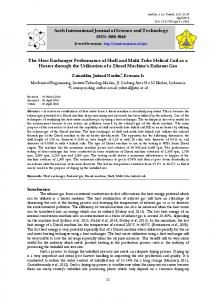
2. CASE STUDY A typical interacting chemical process for heating consists of a chemical reactors and a heat exchanger system. The process fluid which is the output of the chemical reactor is stored in the storage tank. The storage tank supplies the fluid to the heat exchanger system. The heat exchanger heats up the fluid to a desired set point using super-heated steam at 180 C supplied from the boiler. The storage tank supplies the process fluid to a heat exchanger system using a pump and a non-returning valve. The super-heated steam comes from the boiler and flows through the tubes, whereas the process fluids flow through the shells of the heat exchanger system. After the steams heat up the process fluid, the condensed steam at 100 C goes out of the heat exchanger system. There is also a path of non-condensed steam to go out of the shell and heat exchanger system in order to avoid the blocking of the heat exchanger. Different assumptions have been considered in this research paper. The first assumption is that the inflow and the outflow rate of fluid are same, so that the fluid level is maintained constant in the heat exchanger. The second assumption is the heat storage capacity of the insulating wall is negligible. In this feedback process control loop, the controller is reverse acting, the valve used is of air to open (fail-close) type. A thermocouple is used as the sensing element, which is implemented in the feedback path of the control architecture. The temperature of the outgoing fluid is measured by the thermocouple and the output of the thermocouple (voltage) is sent to the transmitter unit, which eventually converts the thermocouple output to a standardized signal in the range of 4-20 ma. This output of the transmitter unit is given to the controller unit. The controller implements the control algorithm, compares the output with the set point and then gives necessary command to the final control element via the actuator unit. The actuator unit is a current to pressure converter and the final control unit is an air to open (fail-close) valve. The actuator unit takes the controller output
57
International Journal of Computer Applications (0975 – 8887) Volume 121 – No.11, July 2015 in the range of 4-20 ma and converts it in to a standardized pressure signal, i.e. in the range of 3-15 psig. The valve actuates according to the controller decisions. Figure 1 show the basic feedback control scheme implemented in a heat exchanger system [3]. There can be two types of disturbances in this process, one is the flow variation of input fluid and the second is the temperature variation of input fluid. But in practice the flow variation of input fluid is a more prominent disturbance than the temperature variation in input fluid. So, in feed forward control loop, the input fluid flow is measured and the disturbance in the flow is controlled using a feed forward controller. The output of the feedback and the feed forward controller is added and the resultant output is given to thee control valve. With the addition of feed forward controller the control performance is further optimized [4]. Figure 1 shows the basic feedback control scheme implemented in a shell and tube heat exchanger system.
Gain of I to P Converter Disturbance Variables
0.75
Critical Gain Transfer function of the Sensor
Kc
4. PID CONTROLLER The Characteristic equation (1+ G(s)* H(s) = 0) in this case is obtained as follows: 900s3 + 420s2 + 43s + 0.798Kc + 1 = 0
(1)
Applying Rout stability criterion in equation (1) gives Kc as 23.8. The auxiliary equation is shown in equation (2) 420s2 + 0.798Kc + 1 = 0
(2)
From equation (2) ω = 0.218 and T = 28.79 The equation of PID controller is shown in equation (3)
Table 3. The rule base for fuzzy (7 memberships)
e(t)
Fig 1: Flowchart of heat exchanger system
3. EXPERIMENTAL DATA Experimental data used for mathematical modeling of heat exchanger system shown in table 1 and table 2. Table 1. Experimental Data Parameter Exchanger response to the steam flow gain Time constant Exchanger response to variation of process fluid flow gain Exchanger response to variation of process temperature gain Control valve has capacity Time constant of the control valve The range of sensor Time constant of sensor
Value 50o C /(kg/sec) 30 sec 3o C/kg/sec Exchanger 1o C /Kg/sec
1.6 kg/sec of steam 3 sec 50o C to 150o C 10 sec
Table 2. Transfer function of disturbance variables Parameter
Transfer function of disturbance variables
Transfer function of the Process Gain of the Valve Transfer function of the Valve
0.133
Δe(t)
NB
NS
NM
Z
PS
PM
PB
NB
NB
NB
NB
NB
NM
NS
Z
NM
NB
NB
NB
NM
NS
PS
PS
NS
NB
NB
NM
NS
NS
PS
PS
Z
NB
NS
NS
Z
Z
PM
PM
PS
NM
NS
Z
PS
PS
PB
PB
PM
NS
Z
PS
PM
PM
PB
PB
PB
Z
PS
PM
PB
PB
PB
PB
According to Zeigler-Nichols tuning criteria [5]; Kp=0.6Kc, Ti=0.5T and Td=0.125T. For the PID controller in the heat exchanger, the values of tuning parameters are obtained as Kp=14.28, Ti=14.395, Td=3.59 P= Kc = 23.8 I= Kc/Ti = 0.99 D= Kc*Td= 85.446 For the PID controller in the heat exchanger, the values of tuning parameters obtained are Kp=14.28, τi=14.395, τd=3.59 and P= 23.8, I= 1.65, D=85.442.
5. FEEDBACK AND FEED-FORWARD CONTROLLER In feed forward controller [6] we have tried to regulate the flow disturbance of the input fluid. Gp(s) is the transfer function of the process where as Gd(s) is the transfer function of flow disturbance as shown in equation (4) and equation (5).
(4)
58
International Journal of Computer Applications (0975 – 8887) Volume 121 – No.11, July 2015
The transfer function of the feed-forward controller is sown in equation (6) and equation (7)
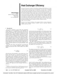
PID controller in figure 7 and figure 8. Figure 9 shows the enchantment when using 9 memberships rule base fuzzy instead of 7 memberships. Finally the genetic controller implemented in figure 10 and figure 11 to reach zero overshoot and minimum settling time. Figure 12 shows the number of generations for genetic algorithm versus OSSTM. Figure 13 shows a comparison of step response for different controllers; our work (Fuzzy9 and GA) and [3].
9. RESULTS AND OBSERVATIONS
Here, ‘λ’ is the filter parameter, whose range is from 0 to 1. It has been used to make the transfer function semi proper
6. FUZZY LOGIC CONTROLLER Previous study has been done to reach the optimum coefficients of PID and PI using fuzzy algorithm [7]. In this paper, multi-valued logic is fuzzy logic. Fuzzy logic is derived from fuzzy set theory. It deals with reasoning, approximations rather than precise values. The rule base for fuzzy for 7 memberships is shown in table 3, Where NB indicates Negative Big, NM indicates Negative Medium, NB indicates Negative Big, Z indicates Zero, PS indicates Positive Small, PM indicates Positive Medium, PB indicates Positive Big. Designing a good fuzzy rule base is the key to obtain satisfactory control performance for a particular operation. Classical analysis and control strategy are incorporated in the rule base. The rule base used in simulation and each rule has the form IF e(t) is NB AND Δe(t) is NB THEN u(t) is NB. r. At last defuzzified output is obtained from fuzzy inputs. In this research work centroid method of de-fuzzification is used. On the other hand, 9 memberships rule base as shown in table 4 can replace the 7 memberships rule base to obtain the minimum overshoot and settling time. Very big positive (VPB) and very big negative (VNB) is added to the rule base as shown in table 4.
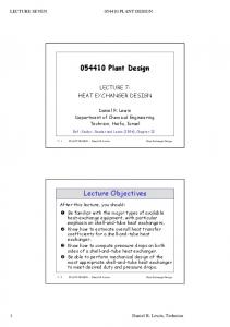
7. GENETIC CONTROLLER Genetic controller depend on genetic algorithm [8] which consists of three main steps, initialization of population (usually random), evaluation of fitness function and finally generation of new population. In random initialization of population, the initial population is created randomly with corresponding number of chromosomes. Each chromosome consists of number of genes. In evaluation of fitness function all the chromosomes of the initially created population are evaluated by means of a fitness function. After evaluating the fitness of the chromosomes of the initial population, a new population is created. The creation of a new generation is performed basically in three stages, reproduction, crossover and mutation. The overall goal of this step is to obtain a new population with chromosomes which have high fitness values. Figure 2 shows the topology of genetic algorithm. A new figure of merit is defined to reach less overshoot ratio and settling time which is called OSSTM (overshoot settling time mean). OSSTM is defined as the mean value of the overshoot error and the settling time error.
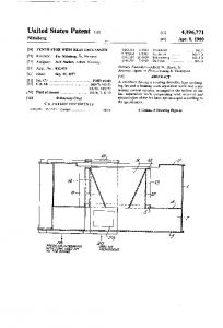
8. SIMULATION AND TESTING Figure 3 and figure 4 show the step response of heat exchanger with feedback process using SIMULINK on MATLAB 2012a. However, Figure 5 and figure 6 show the step response for heat exchanger with feed forward and feedback process. Fuzzy controller takes place to replace the
The simulation results clearly shows that the fuzzy controller gives a much better control of temperature rather than classical PID controller and PID controller in conjunction with feed forward controller. To evaluate the performance of the different controllers we have considered two parameters of the step response of the system. The first parameter is the maximum overshoot and the 2nd parameter is the peak time and 3rd is the settling time. In all the fifth controllers these three parameters are evaluated and a comparative study of their performance has been shown in table 5.
Fig 2 : Flowchart of genetic algorithm
10. CONCLUSION This paper takes a case study of shell and tube heat exchanger system and evaluates different methods to control the outlet fluid temperature. Four different kinds of controllers are designed to control the outlet temperature of fluid and the performances of these controllers are evaluated. By applying the genetic controller the overshoot ratio reduced to be 0 % and the settling time is reduced to be 110 second. In future scope of this paper an existing, PSO optimization can be applied to reach better settling time. Furthermore, the number of rule base should be optimized to reach the optimum solution with minimum numbers of rule base.
11. REFERENCES [1] Padhee, Subhransu, Yuvraj Bhushan Khare, and Yaduvir Singh. "Internal model based PID control of shell and tube heat exchanger system." In Students' Technology Symposium (TechSym), 2011 IEEE, pp. 297-302. IEEE, 2011. [2] Tabatabaee, Sajad, Pegah Roosta, Mokhtar Sha Sadeghi, and Alireza Barzegar. "Fuzzy PID controller design for a heat exchanger system: The energy efficiency approach." In Computer Applications and Industrial Electronics (ICCAIE), 2010 International Conference on, pp. 511515. IEEE, 2010. [3] Satyendra Dhakad, Dilip Dandotiya, P. K. Pandey and D. B. V. Singh.'' An Intelligent Control Strategies
59
International Journal of Computer Applications (0975 – 8887) Volume 121 – No.11, July 2015 Implemented on Heat Exchanger System: A Case Study.'' International Journal of Emerging Technologies in Computational and Applied Sciences, 6(3), SeptemberNovember, 2013, pp. 195-200.
Temperature Control of a HTST Heat Exchanger", 2th Mercosur Congress on Chemical Engineering and 4th Mercosur Congress on Process Systems Engineering, Sao Paulo, Brazil, 2004.
[4] Khare, Yuvraj Bhushan, and Yaduvir Singh. "PID control of heat exchanger system." International Journal of Computer Applications 8, no. 6 (2010): 22-27.
[7] Maidi, A., Diaf, M., and Corriou, J. P., "Optimal Linear PI Fuzzy Controller Design of a Heat Exchanger", Chemical Engineering and Processing, Vol.47, PP.938945, 2008.
[5] Duka, A-V., and S-E. Oltean. "Fuzzy control of a heat exchanger." In Automation Quality and Testing Robotics (AQTR), 2012 IEEE International Conference on, pp. 135-139. IEEE, 2012. [6] Berto, M. I., and JR, V. S., "Configuration of PID / Feed Back and PID / Feed Back / Feed Forward Controllers in
[8] Mitchell, Melanie. An introduction to genetic algorithms. MIT press, 1998.
12. APPENDIX
Fig 3 : Simulink model of process with feedback PID controller with disturbance.
Fig 4 : Step response of feedback PID controller with disturbance
Fig 5 : Simulink model of process with feedback and Feed-forward PID controller with disturbance
60
International Journal of Computer Applications (0975 – 8887) Volume 121 – No.11, July 2015
Fig 6 : Step response of process with feedback and feed-forward controller
Fig 7 : Simulink model of fuzzy controller
Fig 8 : Step response of process with fuzzy controller 7memberships
61
International Journal of Computer Applications (0975 – 8887) Volume 121 – No.11, July 2015 Table 5. Comparison between different implementation of heat exchanger Parameters
Feedback PID
Feedback and Feed forward PID
Fuzzy Controller
Fuzzy Controller
7 memberships
9 memberships
Genetic Controller
Overshoot (%)
76
40
1.8
0.5
0.03
Peak Time(Sec)
35
41
120
120
120
Settling Time(Sec)
200
145
130
114
110
Fig 9 : Step response of process with fuzzy controller 9memberships
Fig 10 : Simulink model of Genetic Controller
62
International Journal of Computer Applications (0975 – 8887) Volume 121 – No.11, July 2015
Fig 11 : Step response of process with genetic controller
Fig 12 : The generations number versus OSTTM for genetic algorithm
Fig 13 : Comparison of step response for different controllers
IJCATM : www.ijcaonline.org
63