APPLIED PHYSICS LETTERS
VOLUME 83, NUMBER 21
24 NOVEMBER 2003
In-plane polarization anisotropy and polarization rotation for M -plane GaN films on LiAlO2 Pranob Misra, Yue Jun Sun, Oliver Brandt, and Holger T. Grahna) Paul-Drude-Institut fu¨r Festko¨rperelektronik, Hausvogteiplatz 5–7, 10117 Berlin, Germany
共Received 5 August 2003; accepted 1 October 2003兲 We investigate the dependence of the transmittance spectra of strained M -plane GaN films on the angle of the linear in-plane polarization, with the c axis of the underlying wurtzite crystal structure in the film plane. Because of the reduced in-plane symmetry and the large in-plane anisotropic strain, the transmission spectra for an arbitrary in-plane polarization angle can be directly derived from two transitions with polarizations parallel and perpendicular to the c axis. Since the energy gap for these two polarizations is shifted by more than 50 meV, the M -plane GaN film becomes dichroic, resulting in a polarization rotation after transmission for energies between the two gaps for an initial angle of 45° by as much as 40° towards the c axis. © 2003 American Institute of Physics. 关DOI: 10.1063/1.1630168兴 Optically anisotropic materials are used to fabricate devices such as polarization-sensitive photodetectors 共PSPDs兲, in which the state of polarization is of critical importance for optical information processing. The advantage of intrinsically anisotropic materials for the fabrication of PSPDs is that it allows for the miniaturization of the detection system, leading to large-scale integration and easier alignment. Isotropic materials such as GaAs can exhibit a polarization anisotropy in the in-plane dielectric function, when anisotropic strain reduces the underlying symmetry of the valence bands 共VBs兲, resulting in a mixing of heavy- and light-hole states.1 Modulators based on the rotation of the polarization vector have been demonstrated in uniaxially strained, 关001兴oriented GaAs/共Al,Ga兲As multiple quantum wells 共MQWs兲2,3 and biaxially strained 关110兴-oriented MQWs.4 The anisotropic crystal properties of CuPtB -type ordered materials such as In0.5Ga0.5P alloys have been increasingly utilized for devices such as tunable polarization converters5 and polarized light-emitting diodes6 as well as a device feature such as polarization stabilization of vertical-cavity surfaceemitting lasers.7,8 Polarization threshold switches9 and resetset flip flops10 have also been realized using ordered In0.5Ga0.5P alloys, which exhibit different absorption coeffi¯ 兴 directions. cients along the 关011兴 and 关011 Recently, it has been shown that strained M -plane GaN films are a potential candidate for the fabrication of PSPDs,11,12 since the c axis of the wurtzite crystal structure lies in the film plane. Theoretical calculations of the strain dependence of the interband transition energies as well as the oscillator strengths reveal that for anisotropically strained M -plane GaN with sufficiently large strain values the VB structure 共VBS兲 is modified in such a way that the corresponding transitions with electrons in the conduction band T 1 , T 2 , and T 3 can be fully x-, z-, and y-polarized, respectively.13 In this letter, we study the in-plane polarization anisotropy and polarization rotation for an anisotropically strained M -plane GaN film with the c axis of the wurtzite crystal structure lying in the film plane. The transmission spectrum a兲
Electronic mail:
[email protected]
for an arbitrary in-plane polarization angle is a linear combination of the transmission spectra originating from two transitions with polarizations parallel and perpendicular to the c axis. An incident linearly polarized light beam with an energy between these two transitions is rotated after transmission through the film. For an initial polarization angle of 45°, the measured angle of polarization rotation can be as large as 40°, which corresponds to about 90% of its maximum value. LiAlO2 has a tetragonal unit cell with lattice constants a⫽b⫽5.1687 Å, which is almost equal to c GaN , and c ⫽6.2679 Å, which is about 2a GaN . Therefore, the M plane of GaN exhibits a rather good lattice matching with the 共100兲 face of LiAlO2 . The M -plane GaN film was grown by rf plasma-assisted molecular-beam epitaxy on a ␥ -LiAlO2 共100兲 substrate.14,15 The film thickness of 0.7 m was determined by scanning electron microscopy. The M -plane orientation of the film and its single phase nature were verified by high-resolution triple-axis x-ray diffraction 共XRD兲. The XRD measurement performed at 295 K revealed that the film is under biaxial compressive strain of ⑀ y y ⫽0.57% 共the y direction is perpendicular to the M plane兲 giving rise to an anisotropic in-plane strain with 兩 ⑀ xx 兩 and 兩 ⑀ zz 兩 共the z direction is parallel to the c axis in the M plane兲 being both larger than 0.2%. The anisotropic compressive strain is due to the anisotropic mismatch of the lattice con¯ 00) and ␥ -LiAlO2 (100), which at stants between GaN(11 room temperature is ⫺0.3% and ⫺1.7% in the z and x direction, respectively. At low temperatures, the lattice mismatch increases due to the difference in the thermal expansion coefficients of the two materials. The polarized transmittance was measured using a monochromatic beam from a Xe arc lamp filtered by a 0.64 m monochromator 共energy bandpass of about 4 meV兲. The incident beam was linearly polarized with a Glan–Taylor prism. The measurement of the polarization rotation after transmission through the film was carried out using a photoelastic modulator and an analyzer as described by Oakberg.16 In order to remove any rotation by the substrate, we attached a second LiAlO2 crystal on the substrate with the crystal orientation rotated by 90°. The light was detected with an
0003-6951/2003/83(21)/4327/3/$20.00 4327 © 2003 American Institute of Physics Downloaded 19 Nov 2003 to 62.141.165.51. Redistribution subject to AIP license or copyright, see http://ojps.aip.org/aplo/aplcr.jsp
4328
Misra et al.
Appl. Phys. Lett., Vol. 83, No. 21, 24 November 2003
UV-enhanced photodetector connected to a lock-in amplifier. The k•p approach to calculate the band structure reveals that for M -plane GaN under biaxial anisotropic compressive strain the VBS is modified in such a way that only two transitions T 1 and T 2 have to be considered for light polarized in the M plane.13 These two transitions occur for light linearly polarized parallel to the z axis (E储 c) and parallel to the x axis (E⬜c). Therefore, we expect that for light polarized at an arbitrary angle with respect to the c axis the transmittance becomes a linear combination of the transmittance for the two orthogonally polarized transitions T 1 and T 2 . The calculation of the transmittance and reflectance of multilayered system is usually performed using the transfer matrix method 共TMM兲 because of its power to deal with multiple reflections at the various interfaces. In the case of an isotropic layered system, the TMM involves only the manipulation of 2⫻2 matrices, since the electromagnetic wave can be expressed by two independent modes. However, the M -plane GaN film is clearly an anisotropic medium, since the interband-transition oscillator strength depends on the inplane polarization angle.12,13 In such anisotropic media, the electromagnetic wave is expressed by four modes, two for E储 c and two for E⬜c, resulting in a 4⫻4 matrix.17 We will apply this formalism to our particular system, which consists of a thin M -plane GaN film on a thick LiAlO2 substrate. Both the film and the substrate are anisotropic media with different dielectric constants for the two orthogonal directions. Following Yeh,17 we obtain
冉冊冉 Az Bz Ax Bx
⫽
M 11M 12M 13M 14 M 21M 22M 23M 24 M 31M 32M 33M 34 M 41M 42M 43M 44
冊冉 冊 Cz Dz Cx Dx
,
共1兲
where A z and A x (C z and C x ) denote the amplitudes of the waves traveling before the system 共after the system兲 in air to the right with a polarization parallel to the z and x axis, respectively, while B z and B x (D z and D x ) denote the corresponding amplitudes for waves traveling before the system 共after the system兲 in air to the left. Since we consider the transmission under normal incidence, the axes in the laboratory frame overlap with the optical axes of the uniaxial medium. Therefore, the matrix elements M 13 , M 14 , M 23 , and M 24 as well as M 31 , M 32 , M 41 , and M 42 are all equal to zero so that the 4⫻4 matrix is reduced to a block diagonal form with two 2⫻2 matrices, corresponding to the two primary directions, i.e., z and x. Since the final medium 共air兲 is considered to be semi-infinite, there are no traveling waves to the left so that D z and D x are equal to zero. After multiplication, we therefore obtain
冉冊冉 冊 Az Bz Ax Bx
⫽
M 11C z M 21C z M 33C x M 43C x
.
共2兲
The transmittance for E储 c (E⬜c) is then given by T 储 ⫽1/兩 M 11兩 2 (T⬜ ⫽1/兩 M 33兩 2 ). The transmittance T( i ) for an arbitrary initial polarization angle i can be expressed as T 共 i 兲 ⫽T 储 cos2 共 i 兲 ⫹T⬜ sin2 共 i 兲 ,
共3兲
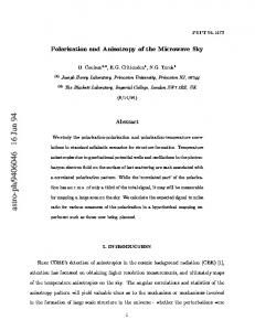
FIG. 1. Measured transmission spectra 共symbols兲 for several polarization angles i between 0° and 90° in steps of 15° at 共a兲 6 and 共b兲 295 K for the M -plane GaN film. The solid lines for i ⫽15°–75° indicate the result of the calculation according to Eq. 共3兲.
where T 储 and T⬜ denote the transmittance for i ⫽0° and i ⫽90°, respectively. Note that the transmittance should be exactly the same for i and 180°⫺ i . A similar expression exists for the transmittance T as a function of the polarization angle after transmission f through the film 1 1 1 ⫽ cos2 共 f 兲 ⫹ sin2 共 f 兲 . T共 f 兲 T储 T⬜
共4兲
The polarization angle after transmission f is related to i by
冋
f ⫽arctan tan共 i 兲
冑 册
T⬜ , T储
共5兲
For any initial polarization angle 0⬍ i ⬍90°, this equation implies that in the energy region, where T⬜ is zero, but T 储 is finite, f ⫽0°, i.e., the initial polarization will be completely rotated back to be parallel to the c axis after transmission. The measured transmittance under normal incidence of the M -plane GaN film is shown in Figs. 1共a兲 and 1共b兲 by the full symbols for polarization parallel ( i ⫽0°) and perpendicular to the c axis ( i ⫽90°) for 6 and 295 K, respectively. At both temperatures, we observe a significant shift of the effective energy gap towards higher energies for i ⫽0°, i.e., E储 c, in comparison to i ⫽90°, i.e., E⬜c. The band gap increases by 49 meV 共60 meV兲 at 295 K 共6 K兲. The larger separation at low temperatures may be due to a higher inplane strain because of the larger thermal expansion coefficient mismatch compared to room temperature. A different inhomogeneous broadening of the two transitions at the two temperatures could also contribute to the difference in the separation. Note that the energy scales in Figs. 1共a兲 and 1共b兲 are identical in order to clearly demonstrate the redshift of the energy gap from low to room temperature. The different energy gaps for the two polarizations occur, because the
Downloaded 19 Nov 2003 to 62.141.165.51. Redistribution subject to AIP license or copyright, see http://ojps.aip.org/aplo/aplcr.jsp
Misra et al.
Appl. Phys. Lett., Vol. 83, No. 21, 24 November 2003
three uppermost VBs have changed their symmetry and energy separation due to the anisotropic in-plane strain as discussed in Ref. 13. In order to experimentally prove the independence of the two transitions for i ⫽0° and 90°, we have measured the angular dependence of the transmittance for i between 0° and 180°. First, we confirmed that the transmittances for i and 180°⫺ i , e.g., for 60° and 120°, are the same. Second, we measured T( i ) for i ⫽15° to 75° in steps of 15°, the results of which are shown by the open symbols in Fig. 1. Using Eq. 共3兲, we calculated the transmittance for different values of i from the measured transmittances T 储 ( i ⫽0°) and T⬜ (90°). The solid lines in Fig. 1 show the calculated transmittances, which agree very well with the measured data, proving the independence of the two transitions for i ⫽0° and 90°. A consequence of the large in-plane anisotropy is the rotation of the polarization vector in the energy range, where the transmittances 共absorption coefficients兲 for the two orthogonal polarizations are very different. In this energy range, the film is dichroic. An incoming beam linearly polarized at an angle i with respect to the c axis will be rotated to f according to Eq. 共5兲 by
冋
⌽⫽ i ⫺ f ⫽ i ⫺arctan tan共 i 兲
冑 册
T⬜ . T储
共6兲
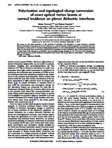
Since in the energy range of interest T⬜ ⬍T 储 共cf. Fig. 1兲, the polarization rotation angle ⌽ will be positive so that the rotation will occur towards the c axis. In the ideal case, when T⬜ becomes orders of magnitude smaller than T 储 , the rotation angle ⌽ will become almost equal to i . Experimentally, however, the ratio T⬜ /T 储 is considerably larger than in the ideal case due to a finite signal-to-noise ratio. Furthermore, the incident linearly polarized light will become elliptically polarized during transmission, since also the indices of refraction are different for both polarizations in this energy range, i.e., both the film and the substrate are birefringent. Figures 2共a兲 and 2共b兲 show the measured 共full symbols兲 and calculated 共open symbols兲 polarization rotation angles for linearly polarized light with i ⫽45° at 6 and 295 K, respectively, as a function of energy. The agreement between the measured and calculated curves is very good. Note that in comparison to ZnO, for which the largest measured rotation angle is 10°,18 the maximum measured rotation angle for M -plane GaN at 6 K is almost equal to 40°, which corresponds to about 90% of the expected rotation angle of 45°. According to Eq. 共6兲, the smaller the value of the ratio T⬜ /T 储 , the larger the experimentally achievable rotation angle. Since the shift of the energy gap between the two polarization directions is much larger for our M -plane GaN film than for the ZnO film in Ref. 18, the minimum value of the ratio T⬜ /T 储 becomes much smaller for the GaN film in comparison to the ZnO film. This difference demonstrates the advantage of M -plane GaN over ZnO for devices based on polarization rotation. In summary, we have demonstrated that for anisotropically strained M -plane GaN films with large values of the in-plane strain the transmittance for an arbitrary in-plane polarization angle can be described by a linear combination of the transmittances originating from two transitions being po-
4329
FIG. 2. Measured 共full squares兲 and calculated 共open circles兲 rotation angle ⌽ of the polarization vs energy for i ⫽45° at 共a兲 6 and 共b兲 295 K for the M -plane GaN film.
larized parallel and perpendicular to the c axis. At the same time, M -plane GaN films can produce a very large rotation of the polarization vector, because within a certain energy range the transmittance for one polarization direction is orders of magnitude smaller than the transmittance for the orthogonal polarization direction. 1
H. Shen, M. Wraback, J. Pamulapati, P. G. Newman, M. Dutta, Y. Lu, and H. C. Kuo, Phys. Rev. B 47, 13933 共1993兲. 2 H. Shen, M. Wraback, J. Pamulapati, M. Dutta, P. G. Newman, A. Ballato, and Y. Lu, Appl. Phys. Lett. 62, 2908 共1993兲. 3 H. Shen, J. Pamulapati, M. Wraback, M. Taysing-Lara, M. Dutta, H. C. Kuo, and Y. Lu, IEEE Photonics Technol. Lett. 6, 700 共1994兲. 4 D. S. McCallum, X. R. Huang, A. L. Smirl, D. Sun, and E. Towe, Appl. Phys. Lett. 66, 2885 共1995兲. 5 R. Wirth, A. Moritz, C. Geng, F. Scholz, and A. Hangleiter, Appl. Phys. Lett. 69, 2225 共1996兲. 6 E. Greger, K. H. Gulden, P. Riel, H. P. Schweizer, M. Moser, G. Schmiedel, P. Kiesel, and G. H. Do¨hler, Appl. Phys. Lett. 68, 2383 共1996兲. 7 K. D. Choquette, R. P. Schneider, Jr., and J. A. Lott, Opt. Lett. 19, 969 共1994兲. 8 Y. H. Chen, C. I. Wilkinson, J. Woodhead, J. P. R. David, C. C. Button, and P. N. Robson, IEEE Photonics Technol. Lett. 9, 143 共1997兲. 9 E. Greger, P. Riel, M. Moser, T. Kippenberg, P. Kiesel, and G. H. Do¨hler, Appl. Phys. Lett. 71, 3245 共1997兲. 10 J. Krauss, T. Kippenberg, J. Spieler, P. Kiesel, G. H. Do¨hler, and M. Moser, Electron. Lett. 35, 1878 共1999兲. 11 S. Ghosh, P. Waltereit, O. Brandt, H. T. Grahn, and K. H. Ploog, Appl. Phys. Lett. 80, 413 共2002兲. 12 S. Ghosh, O. Brandt, H. T. Grahn, and K. H. Ploog, Appl. Phys. Lett. 81, 3380 共2002兲. 13 S. Ghosh, P. Waltereit, O. Brandt, H. T. Grahn, and K. H. Ploog, Phys. Rev. B 65, 075202 共2002兲. 14 P. Waltereit, O. Brandt, M. Ramsteiner, R. Uecker, P. Reiche, and K. H. Ploog, J. Cryst. Growth 218, 143 共2000兲. 15 Y. J. Sun, O. Brandt, and K. H. Ploog, J. Vac. Sci. Technol. B 21, 1350 共2003兲. 16 T. C. Oakberg, Linear Birefringence and Optical Rotation 共Hinds Instruments, Hillsboro, OR, 1992兲. 17 P. Yeh, J. Opt. Soc. Am. 69, 742 共1979兲. 18 M. Wraback, H. Shen, S. Liang, C. R. Gorla, and Y. Lu, Appl. Phys. Lett. 74, 507 共1999兲.
Downloaded 19 Nov 2003 to 62.141.165.51. Redistribution subject to AIP license or copyright, see http://ojps.aip.org/aplo/aplcr.jsp