188
IEEE TRANSACTIONS ON INSTRUMENTATION AND MEASUREMENT, VOL. 49, NO. 1, FEBRUARY 2000
Increasing the Performance of Arbitrary Waveform Generators Using Periodic Sigma–Delta Modulated Streams Benoit Dufort and Gordon W. Roberts, Member, IEEE
Abstract—This paper describes a new method to increase the performance of existing arbitrary waveform generators (AWG’s). ) techniques, By encoding the digital words using sigma-delta ( it is possible to decrease the noise floor in a narrow band while keeping the same memory requirements. Calibration techniques to deal with the nonidealities of the AWG are also presented and verified experimentally. Improvements in spurious free dynamic ranges (SFDR’s) of over 40 dB will be demonstrated with commercial test equipment.
coding the signals using sigma-delta modulation techniques to reduce the noise in a narrow band. In this paper, techniques to increase the performance of AWG are described in more detail, and calibration techniques to reduce the effects of the nonidealities are presented. Static, pseudo-dynamic and dynamic calibration methods are described. Experimental results demonstrate the validity of these techniques.
Index Terms—Calibration, jitter, sigma-delta modulation, signal generators, quantization, testing.
II. PERIODIC SIGMA–DELTA MULTI-BIT STREAMS
61
I. INTRODUCTION
T
HE cost of testing mixed-signal and analog integrated circuits is very high and keeps increasing. One reason for this increase in cost is the complexity of the testing equipment. With integrated circuit specifications such as speed and resolution increasing at a rapid pace, automated test equipment (ATE) must be kept up-to-date to ensure proper testing. This is usually done by replacing all or part of the equipment with newer, more powerful machines. This paper explores periodic multi-bit ) generation as a new approach to increase the sigma-delta ( performance of existing arbitrary waveform generators (AWG) and thus prolonging their useful lifetime at little or no cost. Arbitrary waveform generators are used in automated test setups to generate stimuli for the device under test. A typical AWG consists of two main parts: the memory and the DAC. The converter is usually a high-speed Nyquist-rate converter. A pattern is stored in the memory of the AWG and by cycling through this memory and sending each word to the DAC, it is possible to generate an arbitrary band-limited analog signal. An analog lowpass filter is also needed at the output of the DAC to filter the images created by the digital signal. A simplified block diagram of a typical AWG is shown in Fig. 1. Other waveforms are also available with AWG’s, such as frequency shift keying, but they will not be discussed in this paper. The AWG used to obtain the experimental results of this paper is a Hewlett-Packard HP E1445A. It has a memory of 256K and uses a DAC with 13 b of resolution [1]. A method to increase the performance of AWG’s was introduced in [2] and further refined in [3]. It is based on enManuscriot received February 5, 1999; revised November 7, 1999. The authors are with the Microelectronics and Computer Systems Laboratory, McGill University, Montréal, P.Q., Canada H3A 2A7 (e-mail:
[email protected];
[email protected]). Publisher Item Identifier S 0018-9456(00)01044-5.
Oversampling has been used extensively in ADC’s and DAC’s as a way to reduce the effect of quantization noise in the band of interest. By sampling at many times the Nyquist frequency and using feedback, it is possible to shape the quantization noise of the converter out of the band of interest. modulators have been used widely for high accuracy conversion using a coarse DAC (often 1-b). In addition to offering high accuracy, the requirements for the analog reconstruction filters are also reduced [4]. The 1-b DAC has been the prime choice for modulators owing to its inherent linearity. However, more recently, with the advent of dynamic element matching [5]–[8], modulators is becoming the use of multi-bit DAC’s in more and more common. They offer many advantages such as better resolution and increased stability [9]. modulation has been for the genOne application of 1-b eration of high-quality analog signals. The basic idea was to modulate or encode a digital sequence representing the desired analog signal into a single-bit stream of binary bits [10]. Subsequently, this stream is fed from memory to an analog filter from which the analog signal is created. In order to incorporate this signal generator on-chip with little area overhead, the bit-pattern was reduced to a very short length and reproduced periodically to approximate the longer length bit pattern [11]. Optimization techniques were later used to select the samples that will best approximate the signal [2]. This paper is concerned with adapting similar techniques for multi-bit DAC’s, such as those found in AWG’s. As we shall see, improvements of several orders of magnitude in spurious free dynamic ranges (SFDR’s) can be obtained over a narrow band. modulator The periodic stream is generated using the setup shown in Fig. 2. The modulator consists of two main blocks arranged in a negative feedback configuration: a filter and a multi-bit quantizer. The input section denoted by is assumed to be a floating-point number with denoted by is limited to the resoluvery large precision and the output is loaded into the memory tion of the quantizer. The output
0018–9456/00$10.00 © 2000 IEEE
DUFORT AND ROBERTS: INCREASING THE PERFORMANCE OF AWG’S
189
Fig. 1. Simplified block diagram of a typical arbitrary waveform generator (AWG).
Fig. 2. Graphical representation of the technique. (a) Desired signal; (b) quantized signal; (c) optimization; and (d) pattern loaded in the AWG.
of the AWG and is used to produce the desired analog signal. The parameters that impact the quality of the signals generated are summarized in the following subsections. A. Input Signal
change. The NTF, on the other hand, describes the effect of the quantization noise on the output signal and is directly related to according to (2)
The method begins by defining the attributes of the desired analog signal and to mathematically represent this signal by its . It is the objective of the modulator to convert samples this signal into a multi-bit stream that can then be used by the AWG to produce a corresponding analog signal. Owing to the periodic nature of this signal generation method, the frequencies of the input signal should obey the rules of coherent sampling, as described in [13], and repeated here for our convenience (1) is the sampling frequency and is the length of the where should not exceed the stream. Further, the amplitude of modulator, which maximum input level allowable by the will vary with modulator type and order. B. Signal and Noise Transfer Function modulation Two quantities define the behavior of the process: the signal transfer function (STF) and the noise modulator transfer function (NTF). The structure of the illustrated in Fig. 2 has a unity STF for all physical frequencies [12]. Hence, we are guaranteed that the input signal will be encoded into the output bitstream without amplitude or phase
It is desirable to have the NTF approach zero, i.e., be large, around a bandwidth occupied by the signal. In this way, the effect of the quantization noise on the desired signal is minimized. We refer to this action as noise-shaping. One can also envision a situation where we may want to shape the noise away from a band of frequencies not necessarily occupied by the signal. We will have more to say about this in Section III-B. There are two main types of NTFs: one that has a high-pass behavior and one that has a bandstop behavior. The former one acts to eliminate quantization noise at low frequencies thereby modulator with a low-pass behavior. Recall providing the modulation opthat the input signal is not disturbed by the eration. The other situation acts to eliminate noise around a demodulator with a sired signal band thereby providing the bandpass behavior. Using the appropriate filter function it is possible to center the passband region at any frequency . We find that this point in the Nyquist band type of modulator is well suited for handling high-speed signals. modulation are probably aware Readers familiar with 1-b of the limited amplitude range at the input due to instability. Multi-bit modulation does not suffer from the same stringent stability issues and their input amplitude range is greater.
190
Fig. 3.
IEEE TRANSACTIONS ON INSTRUMENTATION AND MEASUREMENT, VOL. 49, NO. 1, FEBRUARY 2000
SFDR versus modulator output length
xN for N equal to 1024.
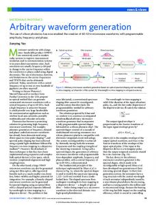
C. Quantizer The number of bits associated with the quantizer should be chosen according to the AWG. Of course, it is best to choose the same number of bits as the DAC, but as will be shown, better quality signals can be obtained even if the number of bits in the modulator quantizer is less than the number of bits in the AWG's DAC. The maximum quantizer value is selected to be larger than the maximum input signal, otherwise the modulator will go unstable. In the results presented in this paper, the quantizer produces levels ranging between 1 and 1, while the input is kept between 0.9 and 0.9. This does not, however, constitute an upper limit for the amplitude range, which will depend on the modulator order, type and the number of bits in the quantizer. D. Optimization Once a long stream has been obtained, the best sequence of must be chosen. This can be done length in the stream using different criteria. The one used in this work is the one that maximizes the SFDR in the desired passband region. The optimization is based on a search, where different length seare evaluated. This can be performed quence coming from sequentially, increasing word by word, or randomly, choosing a different sequence every time. Both methods give similar results, but the random method usually gives better results faster, , while the seas it searches throughout the whole stream . This result quential method scans from the beginning of is illustrated in Fig. 3, which shows the SFDR of the optimized bitstream versus the modulator output length. Simulations have shown that a slight variation in the amplitude of the input sinewave can have significant impact on the quality of the periodic stream approximation. The same effect has been observed by varying the phase of the input signal. This characteristic can be used to further improve the optimization: by slightly varying the amplitude or phase of the sinewave at the input, better SFDR can be obtained. Fig. 4 shows a plot of SFDR versus input amplitude of the sinewave. Notice the small amplitude scale, ranging from 0.4999 V to 0.5001 V. Variations of
Fig. 4. SFDR versus tone amplitude. Note the small amplitude variation.
approximately 18 dB for the SFDR are obtained for a slight variation of less than 40 V in input amplitude. This phenomenon helps the user in achieving better dynamic range by varying the amplitude of the signal within the bounds which has been set. An example of the phase variation is shown in Fig. 5. The same kind of improvement is obtained as in the case of the amplitude variation. An advantage in using the phase variation is that it does not normally have to be small as it is arbitrary in many applications. Since many parameters of the NTF and the input sinewave can be changed, there is an infinitely large number of possible bitstreams. After numerous simulations, a graph that can help in the choice of the modulator NTF was plotted. Usually, the designer or test engineer wants to generate a certain signal with known frequency into a circuit with a fixed bandwidth. Since the bitstreams are generated in software, as mentioned previously, there is no apparent drawbacks in using any NTF order. The length of the bitstream, which is another design parameter, will depend on the memory available in the AWG. The user may also wish to reduce the time it takes to load the patterns into the AWG by using shorter streams. Fig. 6 shows a plot of the SFDR versus the order of the modulator for different bitstream lengths.
DUFORT AND ROBERTS: INCREASING THE PERFORMANCE OF AWG’S
Fig. 5.
191
SFDR versus phase of the input signal.
In this case, the OSR is 32 and the amplitude of the embedded sinewave is 0.5 V (the bitstream has levels of +1 V and −1 V). The modulator is of the lowpass type, but similar graphs have been observed with bandpass modulators. A general trend can be seen from this graph (and others not presented in this paper): for short bitstreams, going up in order increases the SFDR only to a certain point and then it decreases. However, as the number increases, the optimization gives of bits in the bitstream results closer to the response of an ideal modulator output after windowing (shown as a dashed line in Fig. 6).
Fig. 6. Optimization results: SFDR versus modulator order (amplitude V, OSR 32, quantizer 13 b).
=
=
= 0.5
TABLE I
H (z) COEFFICIENTS
III. INCREASING THE PERFORMANCE OF AWGS This section illustrates the improvements obtained by using multi-bit streams with an AWG using two different approaches, in-band and out-of-band testing. The last subsection deals with the tradeoff between resolution and bandwidth. A. In-Band Tone Test The first simulated results are shown in Fig. 7 for an 8-b quantizer and a stream of 2048 points. The graph in Fig. 7(a) shows the 16 384 point FFT for a sinewave signal generated directly by the AWG. By encoding the same signal using an eighth-order modulator with given by (3) with coefficients listed in Table I, and passing the encoded signal through the AWG, we obtain the FFT plot shown in Fig. 7(b). Here we clearly see the reduction in the noise floor (70 dB) around the low frequency region occupied by the signal (i.e., ). When high frequency generation is required, a bandpass type modulator is more suitable. Results of such a modulator are shown in Fig. 8. This time the noise has been pushed down in a band around the desired signal. Once again the graphs in Fig. 8(a) and (b) have the same memory requirements. It should be noted that the noise can be shaped around any signal . If the out-of-band noise is frequency ranging from dc to a concern, it can be suppressed using an additional analog filter between the AWG and the circuit under test. It should be noted that this filter is often unnecessary because of the already low
noise power outside the band obtained with the multi-bit quantizer. The results of Figs. 7 and 8 are simulation results. Fig. 9 shows the spectrum analyzer trace when the stream is loaded inside an AWG and applied to the input of an HP 3588A spectrum analyzer. In this case, a 4-b quantizer was used to clearly encoding. The graph in Fig. 9(a) shows show the benefits of a sinewave generated using the standard technique. The length modulated sequence of the sequence is 1024. In Fig. 9(b), a is shown and an improvement of about 50 dB is achieved. The length of the sequence is still 1024 and therefore the memory requirements are the same for both sequences. The resolution bandwidth of the spectrum analyzer was set to 18 Hz for both , graphs. A clock frequency of 1 MHz was used with MHz, or 250.98 kHz. giving a tone frequency of coded streams can be downloaded from a webExamples of generation at site dedicated to single and multi-bit periodic http://www.macs.ece.mcgill.ca/~roberts/awg.html. B. Out-of-Band Tone Test So far in this paper, the tones of interest were always placed modulator bandwidth. This is of somewhere within the
192
IEEE TRANSACTIONS ON INSTRUMENTATION AND MEASUREMENT, VOL. 49, NO. 1, FEBRUARY 2000
Fig. 7. Comparison between: (a) standard generation and (b) SD generation. Both signals occupy the same memory space in the AWG, 2048 samples of 8 b. Lowpass modulation.
Fig. 8. Comparison between: (a) standard generation and (b) SD generation. Both signals occupy the same memory space in the AWG, 2048 samples of 8 b. Bandpass modulation.
Fig. 9.
Experimental results obtained from an HP E1445A Arbitrary Waveform Generator (4-b DAC). (a) Standard generation and (b) SD generation.
course necessary if filtering to remove the out-of-band noise is performed. Since multi-bit quantizers are used, the power of the noise in the whole Nyquist band remains low even outside the bandwidth of the modulator. It is therefore possible to place the tone anywhere in the Nyquist band, even outside the bandwidth of the modulator. This approach is particularly interesting when distortion measurements are desired or when measuring the influence of an out-of-band interferer. An example is given
through the use of a simulation. A sinewave signal of 13 b precision is sent through a nonlinear system (a voltage buffer). The input and output frequency behavior of the system are in Fig. 10(a) and (b), respectively. It is impossible to measure the nonlinearity of the system because the harmonics are buried in the noise. An arrow in Fig. 10(b) shows where the second encoded 13 b precision harmonic should be. By using a sinewave (same hardware) but this time reducing the noise
DUFORT AND ROBERTS: INCREASING THE PERFORMANCE OF AWG’S
193
Fig. 10.
Nonlinear system test. (a) input signal and (b) output signal. The nonlinearity is small and the second harmonic is buried in the quantization noise (arrow).
Fig. 11.
Nonlinear system test, SD encoding. (a) Input signal and (b) output signal. The second harmonic is apparent now with the lower noise floor.
around the frequency location where the second harmonic should appear, the same test is performed. The resulting input and output PSD’s are plotted in Fig. 11. This time the second harmonic is visible because of the lower noise floor provided encoding. by
bandwidth. Notice the small change in noise level outside the band when compared with the standard case.
C. Tradeoff Between Resolution and Bandwidth
So far, the discussion has been focused on how to generate streams to achieve better performance with existing equipment. However, the equipment will contain nonidealities that streams. While these nonwill affect the performance of the idealities may not appear with standard streams, their effects can streams because of the lower noise be important when using floor. They will set limits on how much improvement can be achieved. Section V will discuss, when possible, different calibration methods which were designed to reduce the effects of the nonidealities presented in this section.
The increase in resolution obtained using sigma-delta coding are made by trading-off bandwidth, not speed. The same frequencies originally possible with the AWG are still encoding. The price to pay is a reduction in possible with bandwidth, because the gains in resolution are obtained only for a limited frequency band. It should be noted however that due to multi-bit quantization, the noise outside the bandwidth, while being slightly higher than for traditional generation, does not increase significantly, which is not the case with single-bit encoding. This tradeoff is shown in Fig. 12. The spectrum of a standard sinewave generated with an AWG is shown in Fig. 12(a). The resolution is constant for the entire Nyquist band. In Fig. 12(b), the sinewave of the same amplitude and frequency is shown, but with an increase resolution in a narrow
IV. NONIDEAL BEHAVIOR
A. Clock Jitter Clock jitter can be defined as a random variation in the period of the clock. This variation will introduce an error in the affected by jitter reconstructed signal. The analog voltage
194
IEEE TRANSACTIONS ON INSTRUMENTATION AND MEASUREMENT, VOL. 49, NO. 1, FEBRUARY 2000
Fig. 12. Tradeoff between resolution and bandwidth. (a) Standard generation and (b) SD generation. Gain of resolution over limited bandwidth. Same speed as standard generation.
will be different from the ideal voltage
by an error voltage
(4) With the help of Fig. 13, the error voltage as
can be expressed
(5) is a unit step function. By renaming the first differwhere ence for simplicity, i.e., (6) the RMS value of the jitter can be derived and written as Fig. 13.
Example of jittered reconstruction.
(7) is the period of the generating frequency. This where equation means that the RMS value of the jitter is proportional to the first difference between the samples stored in the AWG and proportional to the square root of the generating frequency. Like nonlinearities, the amount of jitter introduced by the clock will depend on the AWG and will limit its resolution. It will be shown in Section V-A how this jitter affects the maximum coding can achieve. possible resolution that B. Static Nonlinearities A linear DAC has constant quantization intervals. However, when the DAC is implemented in hardware, the steps are never exactly the same size. If the nonlinearities are assumed to be uncorrelated with the signal, they will create additional noise in the DAC (in addition to the expected quantization noise). The effects of these nonlinearities are mathematically derived in [14]. While this noise may have little effect when using a standard coding scheme, as the system is usually limited by its quantization noise, it can become dominant in the band of interest when
using streams. This is because the noise created by the nonlinearities in the DAC is not modeled by the quantizer and, as such, it does not enter into the feedback loop around the quantizer. C. Dynamic Nonlinearities The nonlinearities treated above in subsection B are static in the sense that the dc transfer characteristic of the DAC will contain uneven steps. The internal DAC must also convert the digital signals to analog levels at high speeds to accommodate high frequency generation. This will introduce errors in the output levels that will be dependent on the frequency and also the signal generated. These nonlinearities tend to be more pronounced for high-speed conversions. Again, since they are not included in streams, their impact can be significant in the generation of the resulting quality of the generated signal. V. CALIBRATION In this section, different methods to reduce the effects of generation are presented. The the nonidealities on the
DUFORT AND ROBERTS: INCREASING THE PERFORMANCE OF AWG’S
195
techniques are fully automated using C programs and the IEEE 488.2 bus connected to the instruments. The AWG used is an HP E1445A, the multimeter is an HP 3458A and the waveforms are observed using an HP 3588A Spectrum Analyzer. Relative accuracy metrics given are calculated according to (8) is where is the number of bits in the quantizer and the maximum integral nonlinearity with offset and gain errors removed [15]. A. Clock Jitter While there is no method to increase the jitter performance of the AWG clock other than to use a better clock source, a formula relating the maximum resolution limited by jitter can be calculated. It is important to approximate the noise introduced by the jitter before attempting calibration, because it sets the limit on how much improvement can be achieved. For a sinewave signal , the RMS value of the of amplitude and frequency derivative is given by
Fig. 14. Static calibration. (a) Step 1: Measuring the DAC transfer function. (b) Step 2: generating the stream with the measured quantizer values.
(9) The value of the first difference derivative
can be found from the
sinewave on the HP AWG, the maximum at and is bits of resolution.
MHz,
B. Static Calibration (10) Substituting (9) in (10) we get (11) and then substituting (11) in (7), we write (12) If we consider the effect of the jitter to have negligible effect on the resolution when its RMS value is less than one LSB (13) then for a full scale sinusoid the maximum resolution that can be achieved is (14) Rearranging (14) to isolate the number of bits
gives (15)
For the HP E1445A, the best clock source available has a typical RMS jitter of 80 ps [1]. As an example, for a full scale amplitude
This method consists of modifying the modulator quantizer to reflect the static nonlinearities introduce by the AWG DAC. Static calibration is illustrated in Fig. 14. The first step is to measure the dc transfer characteristic of the DAC by applying all the AWG input words and measuring the corresponding analog output level. This can be done using a multimeter with an integrating converter since the measurement is done at low speeds. The next step is to use the measured data as the new quantizer and then re-generate the stream. Since the nonlinear levels are now included, they will be shaped by the NTF in the same way the quantization noise is shaped. Fig. 15 illustrates the measured results of a 4-b DAC after a static calibration. The fact that no improvement is apparent is due to the relative accuracy of the AWG DAC (13.1 b). This is more accurate than what is measurable with the spectrum analyzer. To demonstrate the validity of the calibration technique, a different experiment was conducted. Still only 4 b of the AWG were used, but this time the DAC was made nonlinear by changing its codes. This is easily done since the AWG DAC has 13-b resolution. A 4-b DAC with a relative accuracy of 7 b was generated. A bandpass tone was optimized and sent to the generator. The result is shown in Fig. 16(a). As expected, encoding is used, it is impossible to obtain a SFDR even if larger than 42 dB with the nonlinear DAC. A new stream was generated after static calibration. The transfer characteristic of the nonlinear DAC was measured and used to optimize the stream as previously explained (Fig. 14). The results are shown in Fig. 16(b). The improvement is clearly visible, on the order of 38 dB. The same memory requirement and the same DAC
196
IEEE TRANSACTIONS ON INSTRUMENTATION AND MEASUREMENT, VOL. 49, NO. 1, FEBRUARY 2000
Fig. 15. Experimental results of a static calibration. (a) The SD stream optimized without calibration. (b) The SD stream optimized with the measured DAC levels. The similarities in the plots is due to the high linearity of the AWG DAC (relative accuracy 13.1 b).
Fig. 16. Experimental results of static calibration. (a) Noncalibrated stream, with nonlinear DAC (relative accuracy 7 b) and (b) calibrated stream with the same DAC. Both streams have the same memory requirements and use the same voltage levels.
are used in both cases. The difference is only the values sent to the AWG. C. Pseudo-Dynamic Calibration In this technique, rather than measure the transfer function of the DAC and then use it to generate the streams, the hardware is included directly in the loop of the stream generation process. At each time step, a new value is sent to the AWG. The analog signal is measured with the multimeter and sent back to the computer. The technique is illustrated in Fig. 17. It is called pseudo-dynamic because a stream is used for calibration (rather than a staircase signal in the case of the static calibration) but the maximum speed at which the AWG will perform the calibration may not be the speed at which the generation will take place, and thus not all the nonideal dynamic behavior will be captured. An obvious limitation is the inclusion of the multimeter in the signal path. Since it will not be present at the time of generation, any errors introduced by the multimeter will be shaped but will not be reproduced in the signal generation. It is thus necessary that the accuracy of the multimeter be high enough so as not to interfere in the calibration loop. This can be done by increasing the measurement time, which will of course reduce the speed of the calibration and limit the extent of the corrections when the AWG runs at speed. Our first experiment was performed using a linear 4-b DAC. The stream length was set to 1024. A sequence of 8192 was computed and the best stream was chosen. The results are shown
Fig. 17. Pseudo-dynamic calibration. The ideal quantizer is replaced by the AWG and multimeter 35.
in Fig. 18(a). Once again, to verify the technique, a nonlinear DAC was used in the AWG (relative accuracy of 8.3 b). The results of this experiment are shown in Fig. 18(b). As expected, a low noise floor is obtained even with a nonlinear DAC. D. Dynamic Calibration Dynamic calibration can be performed by measuring the DAC transfer function when the AWG is operating at speed. This can
DUFORT AND ROBERTS: INCREASING THE PERFORMANCE OF AWG’S
Fig. 18.
197
Pseudo-dynamic calibration results. (a) Linear DAC and (b) nonlinear DAC.
Fig. 19. Dynamic calibration. (a) Step 1: Generating a stream with an ideal DAC. (b) Step 2: Digitizing the stream and measuring the DAC transfer function. (c) Step 3: Generating the stream with the measured quantizer.
be done using a high-speed multimeter, given that its measurement accuracy is sufficiently high. Once the new transfer function is obtained, a new stream is generated with the measured quantizer in exactly the same manner as with the static calibration case. This is illustrated in Fig. 19. The first step [Fig. 19(a)] consists of generating a stream using an ideal DAC. In step 2 [Fig. 19(b)], this stream is generated at speed using the AWG and digitized with the multimeter. The DAC transfer function is
calculated in the third step and the new measured DAC is used to regenerate a new calibrated stream [Fig. 19(c)]. This approach was verified experimentally. The maximum speed that can be attained by the multimeter while achieving good accuracy is 100 kHz. The measured results are shown in Fig. 20. A nonlinear 4-b DAC (relative accuracy of 6 b) was used as illustrated by the distortion in Fig. 20(a). After calibration, the improved results of Fig. 20(b) are obtained. A stream AWG block diagram with the above modifications is shown in Fig. 24. The above calibration method has a tradeoff between the accuracy of the measurement and the maximum speed at which the signal can be generated. Executing accurate measurements at high speeds can be difficult. However, subsampling the DAC output allows high-speed periodic errors to be captured at low speed. Fig. 21 illustrates this approach. A stream is generated using the AWG clocked at . A high-speed sample-and-hold is placed between the AWG and circuit clocked at the accurate multimeter. Of course, if more time is required to increase the measurement accuracy, the sample-and-hold can , where is an inbe triggered by a clock of teger. The streams must be chosen carefully in order to stimulate all the levels of the DAC needed for software generation. This approach was tested experimentally using the internal sample-and-hold circuitry associated with the HP 3458A multimeter. Rather than directly integrate the signal at its input, the multimeter is made to sample-and-hold the signal using a short sampling burst (2 ns). The held signal is then transformed into digital form using the internal low speed integrating DAC. The results of this experiment are shown in Fig. 22. The noncalibrated DAC results are shown in Fig. 22(a), with large distortion apparent. Once calibrated, the spectrum trace obtained is shown in Fig. 22(b). In this case, the improvement is not as significant as in the other calibration schemes. Some experiments were conducted to explain this phenomenon and the conclusion was that the sample-and-hold did not achieve the manufacturer specified accuracy of 16 b, instead measurements indicate only 10-b accuracy. In the two methods described to dynamically calibrate the AWG, there was no consideration given for the previous sequence of codes. It can give rise to different voltage levels for the same code as illustrated in Fig. 23. This can be thought as some kind of intersymbol interference. Using the same hardware, but
198
Fig. 20. levels.
IEEE TRANSACTIONS ON INSTRUMENTATION AND MEASUREMENT, VOL. 49, NO. 1, FEBRUARY 2000
Experimental results of dynamic calibration. (a) The SD stream optimized without calibration and (b) the SD stream optimized with the measured DAC
Fig. 21. Dynamic calibration using subsampling. The sample-and-hold circuit (S/H) is clocked at low speed of a high-speed AWG.
N +1 times slower than the AWG, which allows the measurement
Fig. 22. Experimental results of dynamic calibration using the subsampling approach. (a) The SD stream optimized without calibration and (b) the SD stream optimized with the measured DAC levels.
with a different program, it would be possible to account for these different steps and include them in the noise shaping loop. A different voltage value could be used in the feedback path depending on the previous code. VI. FUTURE ARBITRARY WAVEFORM GENERATOR So far the techniques presented apply to existing AWG’s that coded streams. Some inwere not designed to generate teresting ideas are presented below that could be built in new coded streams. AWG’s that are designed specifically for
Smaller RAM: coded streams require less bits to obtain the same accuracy as regular streams. New AWG could take advantage of this by reducing their memory capacity. Smaller DAC: Since each word in the stream can be made smaller, a lower resolution DAC can be used. Such a DAC can run at higher speeds and is less prone to jitter. Built-in filter: Afilter is already necessary to filter the images in a standard AWG. By making this filter programmable, coded streams and still have an it would be possible to use analog signal free of out-of-band noise.
DUFORT AND ROBERTS: INCREASING THE PERFORMANCE OF AWG’S
199
[4] J. C. Candy and G. C. Temes, “Oversampling methods for A/D and D/A conversion,” in Oversampling Delta-Sigma Data Converters Theory Design and Simulation, IEEE Press Collection of Paper. Piscataway, NJ: IEEE Press, 1992, pp. 1–25. [5] B. H. Leung and S. Sutarja, “Multi-bit sigma-delta A/D converter incorporating a novel class of dynamic element matching techniques,” IEEE Trans. Circuits Syst. II, vol. 39, pp. 35–51, Jan. 1992. [6] R. W. Adams and T. W. Kwan, “Data-directed Scrambler for Multi-bit Noise Shaping D/A Converters,” U.S. Patent 5 404 142, Apr. 4, 1995. DAC linearity using data [7] R. T. Baird and T. S. Fiez, “Improved weighted averaging,” IEEE Proc. ISCAS'95, vol. 1, pp. 13–16, May. [8] R. Schreier and B. Zhang, “Noise-shaped multi-bit D/A converter employing unit elements,” Electron. Lett., vol. 31, no. 20, pp. 1712–1713, Sept. 28, 1995. [9] P. M. Aziz, H. V. Sorensen, and J. Van Der Spiegel, “An overview of sigma-delta converters,” IEEE Signal Processing Mag., pp. 61–84, Jan. 1994. [10] M. F. Toner and G. W. Roberts, “A BIST scheme for an SNR test of a sigma-delta ADC,” in Proc. 1993 IEEE Int. Test Conf., Baltimore, MD, Oct., pp. 805–814. [11] E. M. Hawrysh and G. W. Roberts, “An integration of memory-based analog signal generation into current DFT architectures,” IEEE Trans. Instrum. Meas., vol. 47, pp. 748–759, June 1998. [12] X. Haurie and G. W. Roberts, “A multiplier-free structure for 1-bit high-order digital delta-sigma modulators,” in Proc. 1995 IEEE Midwest Symp. Circuits and Systems, 1995, pp. 889–892. [13] M. Mahoney, DSP-Based Testing of Analog and Mixed-Signal Circuits. Washington, DC: Computer Society Press of the IEEE, 1987. [14] R. L. Carley, R. Schreier, and G. C. Temes, “Delta-sigma ADC’s with multibit internal converters,” in Delta-Sigma Data Converters, Theory, Design, and Simulation, S. R. Norsworthy, R. Schreier, and G. C. Temes, Eds. Piscataway, NJ: IEEE Press, 1997. [15] D. A. Johns and K. Martin, Analog Integrated Circuit Design. New York: Wiley, 1997.
16
Fig. 23. Different voltage values due to a different previous code (Intersymbol interference).
Fig. 24. Components of a SD AWG. Smaller RAM, smaller DAC, a programmable filter, a digital input, and subsampled analog output from sample-and-hold circuit.
Built-in calibration circuitry: By including some of the calibration circuitry inside the AWG, it is possible to ease the calibration techniques proposed in this paper. Two examples of such circuitry: a direct digital input to the DAC and a high-speed sample-and-hold circuit with clock generator. VII. CONCLUSION This paper extended periodic sigma-delta generation to multi-bit coding. The technique was used to increase the performance of existing AWG’s. Simulation and experimental results show the technique is efficient in reducing the noise floor of the analog signal around the generated tone or elsewhere without hardware modification and using the same amount of memory as traditional digital generation methods. Three different calibration techniques to reduce the effects of the nonidealities were presented, along with experimental results. Static calibration was shown to reduce the effects of mismatches between the step sizes of the DAC transfer function. Pseudo-dynamic and dynamic calibrations on the other hand are useful to reduce the nonlinear effects of high-speed signal generation. Extensive experimental results have proven the usefulness of the technique to reduce the noise floor in a desired bandwidth. REFERENCES [1]
Hewlett Packard HP E1445A Arbitrary Waveform Generator User's Manual, Hewlett-Packard, 1992. [2] B. Dufort and G. W. Roberts, “Signal generation using periodic single and multi bit sigma-delta modulated streams,” in Proc. 1997 IEEE Int. Test Conf., Washington, DC, Nov. 1997, pp. 396–405. [3] B. Dufort and G. W. Roberts, “Increasing the performance of arbitrary waveform generators using sigma-delta coding techniques,” in Proc. IEEE Int. Test Conf., Washington, DC, Oct. 1998, pp. 241–248.
Benoit Dufort was born in Quebec City, Canada, on July 22 1970. He received the B.Sc. degree in electrical engineering from Universite Laval, Quebec, P.Q., Canada, in 1993, the M.A.Sc. degree in engineering science from Simon Fraser University, Burnaby, B.C., Canada in 1995, and the Ph.D. degree in electrical engineering from McGill University, Montreal, P.Q., Canada, in 1999. His research interests include analog and mixedsignal integrated circuit design, analog signal generation for mixed-signal built-in self-test and sigmadelta conversion techniques. In May 1999, he joined Philips Research, Briarcliff Manor, NY, as a Senior Member of research staff, where he is working on analog and mixed-signal integrated circuit design.
Gordon W. Roberts (S'84–M'89) received the B.A.Sc. degree from the University of Waterloo, Waterloo, Ont., Canada, in 1983 and the M.A.Sc. and Ph.D. degrees from the University of Toronto, Toronto, Ont., Canada, in 1986 and 1989, respectively, all in electrical engineering. He is currently an Associate Professor in the Department of Electrical and Computer Engineering, and the Director of the Microelectronics and Computer Systems Laboratory (MACS), both at McGill University, Montreal, P.Q., Canada. Over the years, he has conducted extensive research on analog integrated circuit design and mixed-signal test issues. He has published over 80 papers, coauthored several textbooks related to mixed-signal test and analog integrated circuit design, and contributed nine chapters to other books. Prof. Roberts is presently a Distinguished Lecturer for the IEEE Computer Society. He is past Associate Editor of the IEEE TRANSACTIONS ON CIRCUITS AND SYSTEMS PART II, and an Associate Editor for the IEEE DESIGN AND TEST OF COMPUTERS MAGAZINE. He has received numerous department and faculty awards for teaching electronics to undergraduates, and received several IEEE awards for his work on mixed-signal testing.