Information Modeling for Distributed Energy Resource Integration in IEC 61850 based Substations Ikbal Alia, Mini S. Thomasb, Sunil Guptac and S. M. Suhail Hussaind a,b,d
c
Department of Electrical Engineering, Jamia Millia Islamia, New Delhi, India. Department of Electrical & Electronics Engineering, Maharaja Surajmal Institute of Technology, New Delhi, India Email: a
[email protected], b
[email protected], c
[email protected], d
[email protected]
Abstract— With the increasing deployment of Distributed Energy Resources (DERs) in the distribution system, DERs presents many challenges for smooth and stable operation of the grid. For the effective management of DERs extensive communication between different components of DER and distribution system is required. To standardize the communication methods and modeling of logical nodes required for Intelligent Electronic Devices (IEDs) in DERs, data modeling of DERs is issued in IEC 61850-7-420 standard. This paper has contributed communication modeling of Green Energy Resources (GERs) and other DERs, modeling of messages exchanged among different IEDs with regard to their optimum structure & size and a Substation Communication Network (SCN) topology. End to End (ETE) time delay performance of the designed communication configuration architecture is presented using OPtimized Network Engineering Tool (OPNET). The dynamic performance result in the SCN has demonstrated the successful communication configuration for integrating the DERs in distribution system. Keywords— Communication Modeling, Distributed Energy Resources, IEC 61850; OPNET, Substation Automation System; SCN
I. INTRODUCTION Generation of electrical energy from fossil fuels is currently the single largest source of carbon dioxide emission in the world's atmosphere, making it a significant contributor to climate change or global warming [1]. This has negative consequences for society in general [2]. Though Green Energy Resources (GERs), especially solar and wind, provide alternative energy source in abundance but there is an uncertainty associated with their power output levels due to their dependence on climatic conditions [3]. Hence, are not fit to provide required quality power to the end user’s needs when acting alone [4]. In a scenario, when load demand is growing rapidly, to mitigate the consequences of climate change and to satisfy the increasing demand for power, integration of GERs/Distributed Energy Resources (DERs) to the traditional power grid becomes inevitable [5], [6]. However, increased penetration of DERs in the distribution system has posed many challenges in the operation of distribution system. The communication architecture plays an important role in smooth functioning of DER integrated distribution system. 978-1-4673-6540-6/15/$31.00 ©2015 IEEE
Robust, deterministic and interoperable communication architecture is essential in order to ensure that all DER components exchange information, control commands and real time measurements effectively without any delay or loss. High cost and complexity involved with proprietary communication protocols for integrating DER devices in distribution system has come up with major issues, and demands for communication interoperability among multivendor devices for implementation of communication architectures. IEC 61850-7-420 [7] as an extension to IEC 61850 [8] is a widely accepted standard to standardize the communications between DERs and other equipment. In literature IEC 61850 based communication architectures for automation, protection and monitoring of substations has largely been reported [9], [10]. References [11], [12] have proposed IEC 61850 communication based distribution system protection schemes. Taha et al. [13] and Apostolov [14] presented the object modeling of DERs with IEC 61850-7-420 and its extensions from the control and communication point of view. Kanabar et al. [15] presented the study of different communication systems between DERs and IEC 61850 based distribution system. Communication modeling of GERs/DERs and modeling of messages has led to smooth integration of Green Energy, e.g. solar and wind etc., in the distribution system. SMART, i.e. Standard based, Multi-layered, Available, Resilient and Timely, management has provided secure, reliable and stable electricity supply to the end users. SMART management is made possible through a robust, redundant and deterministic SCN topology. Therefore a hybrid of the GERs and other DERs, SMARTly managed and integrated through robust, redundant and deterministic SCN, is crucial to provide a sustainable, environment friendly and energy efficient power system. This paper presents the information modeling of DER IEDs according to IEC 61850-7-420 and its extensions. Further, an innovative SCN architecture incorporating both communication and components redundancy is proposed. OPtimized Network Engineering Tool (OPNET) modeler is used for the performance simulation of this proposed SCN architecture integrated with DER in distribution system using wired communication technologies [16]. The paper is organized as follows: Section II provides a brief description of IEC 61850 object modeling and communication approach, Section III explains the
communication modeling of IEC 61850 substation IEDs and different DERs system according to IEC 61850-7-420, and Section IV discusses the detailed modeling and the simulation study of communication between different DERs and distribution system using wired communication technologies in OPNET. Finally, Section V presents conclusion. II.
IEC 61850 OBJECT MODELING & COMMUNICATION APPROACH
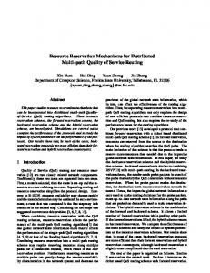
IEC 61850 provides an object oriented modeling approach for power system devices to organize data, configure objects and map them on to protocols, so that they are consistent and interoperable. IEC 61850 standardized data models and ACSI services are mapped over standard communication protocols and hardware such as Transmission Control Protocol (TCP)/Manufacturing Message Specification (MMS) and Switched Ethernet, to make this standard a future proof standard. To reduce the additional overhead caused by TCP/IP layers in transmission time performance, real-time and mission-sensitive messages such as Sampled Values (SVs) from Merging Units (MUs) and Generic Object Oriented Substation Event (GOOSE) messages are mapped to the Ethernet layer of the ISO/OSI communication stack as shown in Fig.1. Further, Network traffic segregation and prioritization through network management features in switched Ethernet avoids delays and plays an important role in the design and real time performance protection applications. Thus, IEC 61850 communication approach and switched Ethernet ‘QoS’ features such as RSTP (IEEE 802.1w), full duplex, priority tagging (IEEE 802.1p), VLAN (IEEE 802.1q), multicast filtering and others allow system designer to optimize the SCN architecture as per IEC 61850-5 performance requirements taking into consideration the constraints of the system [17].
IEDs to the substation. Table I gives the time requirements of different messages of distribution substation and DERs. TABLE I. Information Type Protection information Monitoring and control information
MAXIMUM MESSAGE DELIVERY TIME Internal in substation (ms) 0-4 16
External (DER) to substation (ms) 8-12 1s
IEC 61850 was initially proposed for substation automation systems SASs) later it was extended to utility automation. The new extensions of the standard such as part 7420 defines the logical nodes for DERs, part 90-1 describes the communication between two substations, part 90-5 describes the use of IEC 61850 to transmit synchrophasors information according to IEEE C37.118, part 90-7 describes the Object Models for DER inverters, etc. III.
COMMUNICATION MODELLING OF SMART SUBSTATION AND DER SYSTEM
Non-Conventional Instrument Transformers (NCITs), MUs, Protection & Control IEDs (P&C IEDs), Ethernet switches (ESs), Time Synchronization (TS) sources, and Circuit Breaker IEDs (CB_IEDs) etc. are a part of IEC 61850 SAS. Bay level P&C IEDs are independently connected to process level equipments such as MUs, NCITs through a process bus network. MU IEDs transmits process level data in the sampled value format, as per IEC 61850-9-2 ‘LE’ guidelines, to the bay level IEDs for necessary protection and control functions. CB_IEDs controls the status and condition of circuit breaker on the basis of tripping, status and interlocking commands from P&C IEDs.
Fig. 2. Single line diagram of a typical 220/132 kV D2-1 type substation. Fig.1. ISO/OSI 7-layer communication stack of IEC 61850
The IEC 61850-5 standard specifies the time requirements of IEC 61850 SAS messages, but the time requirements for DERs connected to distribution system are not specified. IEEE 1646 standard [18] gives the time requirements to different types of information messages for external or remote or DER
Fig.2 shows the single line diagram of D2-1 type substation that consists of six (F1-F6) feeder bays), two (TI&T2) transformer bays and one(S) bus section bay [9]. Fig. 3 shows the redundant SCN architecture, drawn for 220/132 kV substation, as shown in Fig.2, where each feeder bay has one MU IED, two P&C IEDs, and one CB_IED. Each transformer bay and bus section bay has two MU IEDs, one CB_IED, and two P&C IEDs.
F2_IEDS_MAIN_2
F6_IEDS_MAIN2
TS
T1_IEDS_MAIN2
T2_IEDS_MAIN2
S_IEDS_MAIN2
STATION_SWITCH_2
CB_IED2 MU_IED2
Process Data P&C_IED2
Trip Signal
STATION_SWITCH_1
Interconnected Links connecting inter-bay Ethernet switches of two ring networks F1_ES11
F2_ES22
F6_ES66
T1_ES11
T2_ES22
S_ES22
Ring 1 Network Ring 2 Network
F1_ES1
F2_ES2
F6_ES6
T1_ES1
T2_ES2
S_ES1
Links connecting Bay IEDs to its own bay switch Links connecting Bay IEDs to the adjacent bay switch
P&C_IED1 TS CB_IED_1 MU_IED1
F2_IEDS_MAIN1
F6_IEDS_MAIN1
T1_IEDS_MAIN1
T2_IEDS_MAIN1
S_IEDS_MAIN1
Redundant NCITs & CB Trip Coils
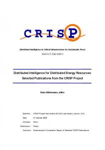
Fig. 3. Innovative IEC 61850 SCN architecture.
This design of this innovative and conceptual SCN architecture is based on the fact that current substation IEDs have redundant Ethernet communication ports. These IEDs run DHP to automatically switch over the communication to back up port when the primary port fails, and hence maintains the continuity and stability in substation operations [19]. This SCN architecture can be generalized to any substation. The way network component redundancy as well as the communication links redundancy is incorporated is the USP of this innovative SCN architecture. This makes this architecture free of single-point-failure, link failure, component failure and
even a protection systems failure. The communication model of GERs/DERs and Substation components is developed using the basic logical nodes (LN) in IEDs. Logical nodes are group of data objects which serve specific functions. The IEDs associated with specific GER/DER/substation components contains the relevant logical nodes needed for communication, according to functions performed by them. The logical nodes associated with different types of GERs like photovoltaic, wind plant and DERs like diesel plant, CHP plant are shown in Fig. 4.
Fig. 4. Organization of DER logical nodes and Logical devices at ECP [7]
IEC 61850-7-420 defines the logical nodes for DER systems except for wind power plant which are defined in a separate standard IEC 61400-25-2 [20]. These logical nodes and data classes are in accordance or compatible with the nodes defined part 7-4.The DER system communication IEDs are modeled with relevant logical nodes defined in the IEC 61850 standards. Modeling of following types of DER systems is presented: 1. Photo Voltaic (PV) system 2. Diesel Generator system 3. Wind plant system Each DER plant is connected to the distribution substation via Electrical Connection Point (ECP). At this point of connection a circuit breaker and metering devices are present. Fig. 4 shows different logical nodes associated with the DER system components. Every DER plant is modeled to have 4 IEDs – ECP control IED, DER control IED, Breaker IED and Measuring Unit (MU) IED. ECP control IED receives the settings, commands or modes from the control center and sets the implement the same at DER. DER control IED corresponds to the controller of each DER which sets or controls the different parameters of the DER plant. Breaker IED corresponds to the circuit breaker connecting DER to the substation and Merging Unit IED corresponds to the CT and PT at the ECP. IV. MODELLING AND SIMULATION USING OPNET
standard and customized network nodes. Table II enlist different network nodes with their description. Fig. 5 shows the customized node models developed in OPNET node model editor, which supports GOOSE, Sample Values and MMS type of traffic. The Merging Unit IED only sends Sample values to other IEDs, in which data is directly mapped on to the MAC layer, is modeled as ‘ethernet_station_adv’ node.
(a)
A. IED Modeling Opnet modeler provides Proto-C based object-oriented modeling approach, with many editors such as Project editor, Node editor, Process editor, Packet editor for detailed customization of the dynamic models of IEC 61850 substation/DER system IEDs, Ethernet switches and fiber optics communication links. TABLE II.
NETWORK NODES AVAILABLE IN SIMULATED SCN ARCHITECTURE
SCN component Type
OPNET Node Model
MU IED
ethernet_station_adv
P&C IED
ethernet_wkstn_adv
CB_IED
ethernet_wkstn_adv
Ethernet switch
ethernet16_switch_ adv
Full Duplex, 100 Mbps
100BaseFX_adv
Full Duplex, 100 Mbps
ethernet_wkstn_adv ethernet_server_adv
Standard Standard
Fiber optics communication links Station PC Server
Description Standard (Support SVs Stack) Customized (MMS & GOOSE stack) Customized (MMS & GOOSE stack)
From Fig. 4 it quite clear that the breaker IED, DER Control IED and ECP control IEDs receive or send the GOOSE, Sample Values and MMS type messages. Hence, the simulated SCNs and DER system make use of the available
(b) Fig. 5. Customized Node models (a) MU IED, (b) Breaker and control IEDs.
B. Simulation and Traffic Modelling Fig. 6 shows the OPNET modeler’s simulated DER system integrated with the proposed SCN. The detail modeling and simulation of the substation can be obtained from [9]. The DER system and all the substation bays are modeled as subnets in project window of OPNET. Each subnet contains
Fig. 6. OPNET’s simulated Innovative SCN architecture with DERs integration.
its corresponding bay IEDs and a bay Ethernet switch. The SCN also consist station server and station PC which are connected to station switch, also all bay switches are connected to the station switch. The DER’s subnet, which contains the DER IEDs and a switch, is connected to the station switches of SCN. The IEC 61850 substation/DER IEDs basically exchange three types of messages. First are the trip/open commands which are exchanged between substation P&C IEDs/DER control and Breaker IEDs. Sometimes these commands are also issued from substation control PC to DER breaker IED. TABLE III.
SIZE OF DIFFERENT MESSAGES EXCHANGED BY DER IEDS
Type of message Trip commands
Source IED
Destination IED
DER Control IED P&C IEDs (substation) Station PC
Sample Values
MU IED
Status Update
DER control IED DER Breaker IED
Packet Size (bytes) 98
DER Breaker IED
substation server/station PC. Table III & IV gives details of the traffic configured in SCN through ‘Application Configuration’, ‘Profile Configuration’, and ‘Task Configuration’ windows of OPNET for all the SAS applications [10]. TABLE IV.
Type of Message
Source IED
Sampled Packets Protection Controls
MU IED
102
DER Control IED Server
150
200
Second types of messages are the sample values of process data from substation CTs/VTs or the current and voltage values at the ECP of DERs. The Merging Unit IEDs send these messages to their corresponding substation P&C IEDs/DER control IED. Third type of messages is status updates in which the substation P&C IEDs/DER controls IEDs and breaker IEDs constantly updates their status to the
Value
P&C IED
File Transfer Status Update
TABLE V.
DER Control IED Server
SIZE OF DIFFERENT MESSAGES EXCHANGED BY SUBSTATION IEDS
Message Type GOOSE Sampled Values MMS Traffic
P&C IED, CB IED
Destination IED P&C IED
Size (Bytes) 102
CB IED P&C IED, CB IED Server Server
104 200 1 MB 200
PERFORMANCE EVALUATION OF 100 MBPS WIRED LAN FOR MESSAGES FROM DER TO SUBSTATION Delay (ms) 0.11 0.14 0.22
100 Mbps Throughput (Kbps) 80 3500 1000
1000 Mbps Delay Throughput (ms) (Kbps) 0.08 80 0.106 3500 0.203
1000
The performance of the communication network is studied for wired configurations. In Fig. 6, the simulation of SCN using wired technology in OPNET Modeler software is presented. Here 100 Mbps wired communication links between DER IEDs and DER switch; and between DER subnet and substation switch are considered. The distance between the substation and DER for the simulation is considered to be 5 km. For the performance evaluation of the SCN architecture, the ETE delay for time-critical messages
and throughput are selected as a key statistics. The results are tabulated in Table V. V. CONCLUSION This paper presented the communication configuration for integrating DER in distribution network. The information modeling of different IEDs of DER plant and substation with the relevant logical nodes as per IEC 61850 standards is discussed. The paper proposed innovative redundant substation communication network architecture. This novel SCN is integrated with DER plant communication network. Hence this communication network paves way for smooth integration of DERs in distribution network. OPNET modeler software is used evaluate the performance of the proposed communication network. The dynamic performance evaluation of the innovative SCN architecture, under various network parameters conditions, has demonstrated its SMART capabilities and ease of integration of DERs. REFERENCES [1] [2]
[3]
[4] [5] [6]
EEA Energy and Environment Report 2008 (Copenhagen, 2008). Climate Change 2007: Climate Change Impacts, Adaptation and Vulnerability Summary for Policymakers. A Report of Working Group II to the Fourth Assessment Report of the Intergovernmental Panel on Climate Change. E. Rikos, S. Tselepis, C. Hoyer-Klick, and M. Schroedter-Homscheid, "Stability and Power Quality Issues in Microgrids Under Weather Disturbances, “ Selected Topics in Applied Earth Observations and Remote Sensing, IEEE Journal of ,” vol.1, no.3, pp.170-179, Sept. 2008. F. Katiraei, R.Iravani, N.Hatziargyriou, and A. Dimeas, “Microgrids management,” Power and Energy Magazine, IEEE , vol.6, no.3, pp.5465, May-June 2008. J. Driesen and F. Katiraei, “Design for distributed energy resources,” Power and Energy Magazine, IEEE , vol.6, no.3, pp.30-40, May-June 2008. Intergovernmental Panel on Climate Change (IPCC) (2011), “IPCC Special Report on Renewable Energy Sources and Climate Change Mitigation” By O. Edenhofer, R. Pichs-Madruga, Y. Sokona, K. Seyboth, P. Matschoss, S. Kadner, T. Zwickel, P. Eickemeier, G. Hansen, S. Schlömer, C. von Stechow (eds), Cambridge University Press, Cambridge, United Kingdom and New York, NY, USA, 1075 pp.
[7] [8] [9]
[10]
[11]
[12]
[13]
[14]
[15]
[16] [17] [18]
[19]
[20]
Part 7-420: Basic communication structure - Distributed energy resources logical nodes, 2009, IEC 61850-7-420, 1st ed. Communication networks and systems for power utility automation 2013, IEC 61850, 2nd ed. T.S.Sidhu and Y. Yin, “Modelling and Simulation for performance evaluation of IEC61850-Based substation communication systems,” Power Delivery, IEEE Transactions on , vol.22, no.3, pp.1482-1489, July 2007. M.S.Thomas and I. Ali, “Reliable, fast, and deterministic substation communication network architecture and its performance simulation,” Power Delivery, IEEE Transactions on , vol.25, no.4, pp.2364-2370, Oct. 2010. M. Adamiak, R. Hunt, A. King, and S. McCreery, “ Application of digital radio for distribution pilot protection and other applications,” in Proc. 2008 IEEE Protective Relay Conf., pp. 310-333. B. Hadzi-Kostova, Z.Styczynski, and R. Krebs, “New protection concepts for distribution systems with dispersed generation,” in Proc. IEEE Power Tech. Conf., pp. 1-6, June 2005. Ustun, T.S.; Ozansoy, C.; Zayegh, A., "Distributed Energy Resources (DER) object modeling with IEC 61850–7–420,” Universities Power Engineering Conference (AUPEC), 2011, 21st Australasian , pp.1-6, 2528 Sept. 2011. A.P.Apostolov, “Modeling systems with distributed generators in IEC 61850,” Power Systems Conference, 2009. PSC '09., pp.1,6, 10-13 March 2009. P. M. Kanabar, M.G. Kanabar, W. El-Khattam, T.S. Sidhu, and A. Shami, "Evaluation of communication technologies for IEC 61850 based distribution automation system with distributed energy resources," Power & Energy Society General Meeting, 2009. PES '09. IEEE, pp.1,8, 26-30 July 2009. OPNET Modeler – OPNET Technologies, [Online], Available: http://www.opnet.com. IEC 61850-5: Communication requirements for functions and device models, IEC INTERNATIONAL STANDARD, July 2003. IEEE Standard Communication Delivery Time Performance Requirements for Electric Power Substation Automation," IEEE Std 1646-2004. I. Ali, M. S. Thomas, S. Gupta, and S. M. Suhail Hussain, “IEC 61850 Substation communication network architecture for efficient energy system automation,” Energy Technology & Policy, Taylor & Francis, 2:1, 82-91, 2015. DOI: 10.1080/23317000.2015.1043475 IEC, Wind Turbines—Part 25: Communications for Monitoring and Control of Wind Power Plants, IEC Std. 61400-25, 2006.


![Nuclear Energy Is Dirty Energy - Nuclear Information and Resource ... [PDF]](https://m.moam.info/img/260x300/nuclear-energy-is-dirty-energy-nuclear-information_648ca334098a9e23088b4670.jpg)


