ues. This paper deals with the development of the. PWM algorithm for the three-phase three-level AC to DC converter based on the switching matrix ap- proach.
ISSN 0005−1144 ATKAAF 42(1−2), 53−61 (2001) Miro Milanovic, Alenka Hren, Franc Mihalic
Input Displacement Factor Correction for Three-Phase Three-Level AC to DC PWM-based Boost Rectifier UDK 621.314.6 IFAC IA 5.5.4;4.7.1 Original scientific paper Pulse width modulation (PWM) strategy for a matrix structured three-phase three-level AC to DC boost rectifier is developed. Such approach has been used on purpose to control the input displacement power factor close to unity. The connection between matrix switching function and PWM requirement very well describes all restrictions that occur in the modulation algorithm. This modulation algorithm enables the input displacement factor correction without an input current sensor. The only necessary control variable is the measured displacement angle between input voltage and input current. Key words: matrix converter, ac-dc converter, switching function, pulse width modulation, input displacement factor
1. INTRODUCTION
A switching matrix analysis in power converter circuits was first investigated in [1] and then more recently, using the generalized high frequency switching strategy, in [2]. Such analyzes offer a pleasant method for understanding the power conversion between sources and sinks through the switching converter circuit. The AC-AC conversion function has been discussed in [2] and [3], where the emphases were done in the modulation strategies and improving the range of three-phase output voltage. In [4] the authors introduced a space vector modulation strategy in the AC to AC converter. In [5] and [6] it is shown that for the hysteresis control of the in-
put phase current and resistive fundamental mains behavior the central point potential can be controlled by an offset of the phase current reference values. This paper deals with the development of the PWM algorithm for the three-phase three-level AC to DC converter based on the switching matrix approach. 2. DESCRIPTION OF CONVERTER BY SWITCHING FUNCTIONS
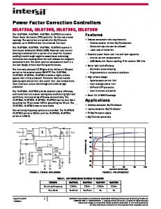
In approaching a design of the switching power converter shown in Figure 1(a) for any application, two related sets of parameters are of paramount
Fig. 1 (a) General switching matrix with current inputs. (b) The rectifier circuit with M = N = 3
AUTOMATIKA 42(2001) 1−2, 53−61
53
M. Milanovic, Alenka Hren, F. Mihalic
Input Displacement Factor Correction ...
interest. The internal currents and voltages of the converter switching loops will determine the selection of active switching device to be used and also auxiliary passive components needed to enable the devices to operate properly. The switching algorithm used to connect the M input lines with the N output lines is based on Figure 1(a). In order to obtain a precise, quantitative means for describing the converter internal structure and external terminal properties, the switching pattern is needed. This can be conveniently done by defining a function, so called a Switching function which has been defined in [1](1): H ij
R|1 =S |T0
for for
Sij = ON Sij = OFF
(1)
N
∑ H ij = 1 , i = 1K M .
j =1
(2)
The switch in the switching matrix connects the Iini current sources from the set of M input variables with Vinj voltage sources from the set of the N output variables. Whenever the switch is OFF, the blocking voltage appears across it. The voltage impressed on the input line i can be written as: N
∑ H ij V out j = 1 , i = 1K M .
(3)
j =1
The voltage across the switches can be obtained as a difference between the voltage on i and line j like: V swij = V ini − V out j .
(4)
Substitution of (3) into (4) gives: N
V swij = ∑ H imV out m − V out j m= 1
i = 1K M , j = 1K N . (5)
The next step to be defined is the current through the switches. In general the Kirchoff's current low valid for output matrix converter current could be expressed as: I out N = −
N −1
∑ I out j .
(6)
j =1
The input current could be represented as a linear combination of output currents as follows: 54
N −1
∑ H ij I out j − H iN I out N , i = 1K M .
j =1
(7)
Equation (6) should be substituted into (7) and finally: I inij =
N −1
N −1
j =1
j =1
∑ H ij I out j − H iN ∑ I out j , i = 1K M .
(8)
The main aim followed in this section was to find the expression for estimating the switches currents. The current through switch can be expression by: (9) I swij = H ij I in , i = 1K M , j = 1K N . i
.
The circuit shown in Figure 1(a) will not operate when the voltage sources are short-connected and when the currents have no path to flow. Because of this the switching function must satisfy next condition:
V ini =
I inij =
It is evident that the current through the switches can be estimated only when the output current is known. From (5) and (9) the internal structure of switching matrix converter was defined. 2.1. Power converter circuits analyzed by switching
Function In previous section the general approach has been introduced and presented. The circuit shown in Figure 1(b) is appropriate for further analysis. Anyway, the next presumptions will make the analysis easier. The number of input and output lines are equal: (10) M = N = 3. The quantitative assessment of switching converter performance and characteristics for AC to DC converter have been analyzed here are: – The current sources (voltage sources with inductors) are presented on the input lines. – The voltage sources/sinks (capacitors) are presented on the output lines. – The power flow has to be bi-directional. For output voltage definition it is necessary to presume the next requirements: – To establish the »output voltage« (Vini, see Figure 1(b)) the three output voltage sources (Voutj) are available. – The blocking voltage on semiconductor switches has to be half of the entire output voltage. 2.1.1. Voltage properties For three-level converter output the voltages will appear on the output capacitors. Because of DC requirements the output voltages could be defined as follows: V out1 = +V o1 V out2 = −V o2
(11)
V out3 = 0 . AUTOMATIKA 42(2001) 1−2, 53−61
M. Milanovic, Alenka Hren, F. Mihalic
Input Displacement Factor Correction ...
After defining the voltage external terminal properties, the internal properties will be further considered. The base of this analysis is given in (5) and (9). Let us define the voltages impressed on switches on the first vertical line. First, consider the switch S11. After expanding (9) the blocking voltage on the switch is: V sw11 = H 11V out1 + H 12 V out 2 + H 13V out3 − V out1 . (12)
e
j
The blocking voltage on the switch S11 has finally two values because of (2): – When H12 = 1 and H13 = 0, the blocking voltage will be: V sw11 = V out 2 − V out1 = −V o1 − V o2 .
From (13) and (14) the next conclusion could be done: When the switch S11 is OFF it must block the negative voltage in both case. For the switch S12 the voltage property can be evaluated by:
e
j
(15)
The blocking voltage on the switch S12 has also two values because of (2): – When H11 = 1 and H13 = 0, the blocking voltage will be:
b
g
V sw12 = V out1 − V out2 = V o1 − −V o2 .
(16)
– When H11 = 0 and H13 = 1, the blocking voltage will be:
b
g
V sw12 = V out 3 − V out2 = − −V o2 .
(17)
From (16) and (17) the next conclusion could be done: When the switch S12 is OFF it must block the positive voltage in both case. For the switch S13 the voltage property can be evaluated by: V sw13 = H 11V out1 + H 12 V out2 − V out 3 .
e
j
(18)
The blocking voltage on the switch S13 has also two values because of (2): – When H11 = 1 and H12 = 0, the blocking voltage will be: (19) V sw = V out − V out = V o1 . 13
1
3
– When H11 = 0 and H12 = 1, the blocking voltage will be: AUTOMATIKA 42(2001) 1−2, 53−61
(20)
From (19) and (20) the next conclusion could be done: When the switch S13 is OFF it must block the positive and negative voltage in both case. 2.1.2. Current properties The current can be evaluated from (8) and (9). For the switch in the first vertical line (8) could be expanded as follows: I in1 = H 11 I out1 + H 12 I out2 − H 13 I out1 + I out 2 . (21)
e
j
Because of (2) it follows:
(13)
– When H12 = 0 and H13 = 1, the blocking voltage will be: (14) V sw11 = V out 3 − V out1 = −V o1 .
V sw12 = H 11V out1 + H 13V out3 − V out2 .
V sw13 = V out 2 − V out3 = −V o2 .
I in1 = H 11 I out1 = I sw11 .
(22)
I in1 = H 12 I out2 = I sw12 .
(23)
I in1 = H 13 I out1 + I out 2 = I sw13 .
(24)
or or
e
j
From (22) appears the current property of switch S11. According to the DC converter output the output current into voltage source Vout1 must have positive direction. For the voltage and current properties of the switch S11 can be supposed: When the switch S11 is OFF it should block the negative voltage, and when it is ON it should conduct the positive current. Such properties are normal for the diode. From (23) appears the current property of switch S12. According to the DC converter output the output current into voltage source Vout2 must have negative direction. For the voltage and current properties of the switch S12 can be supposed: When the switch S12 is OFF it should block the positive voltage, and when it is ON it should conduct the negative current. Such properties are normal for the reverse connected diode. To define the properties of the switch S13 the next consideration from (24) should be done: Because of condition (2) the switching function H11 = = H12 = 0, but the current must have the way to flow. Because of this the switching function in the second vertical line must satisfy next conditions: H22 = 1 and H21 = 0 or H22 = 0 and H21 = 1 and similar for the third vertical line. From this description the next conclusion could be done: When H22 = 1 the switch S13 conducts the positive current which has the same direction as current Iout2. When the switching function H21 = 1 the switch S13 conducts current which has the same direction as current Iout1. The current trough switch S13 could has both directions. According to this for the voltage and 55
M. Milanovic, Alenka Hren, F. Mihalic
Input Displacement Factor Correction ...
current properties of the switch S13 could be done: When the switch S13 is OFF it should block the positive and negative voltage and when it is ON it should conduct the positive and negative current. Such properties are normal for a bi-directional switch. The results of above analysis are summarized in Table 1, where voltage and current characteristics of all switches in first vertical line are defined.
3. SWITCHING PATTERN
For establishing the switching pattern the switching matrix approach is very powerful tool. The power supply voltage and input currents are: V A = V$ cos( ωt )
VC
Table 1. The switching device current and voltage properties S11
S12
Current is:
Positive
Negative
Both
Blocking voltage is:
Negative
Positive
Both
Switching device is:
Diode
Diode
Bi-dir. switch
(25)
I in1 = I$ cos( ωt + ϕ)
S13
Bi-directional switches S13, S23 and S33 can be constructed in five different combinations of diodes and transistors. After it's substitution in the scheme in Figure 1(a) the five different structures, of the three-phase three-level boost rectifier can be established. The varieties of AC to DC converter types have been depicted in Figure 2(a), (b), (c), (d) and (e) respectively.
FH IK = V$ cos FH ωt − 4 π IK , 3
V B = V$ cos ωt − 2 π 3
FH IK = I$ cos FH ωt − 4 π + ϕIK . 3
I in2 = I$ cos ωt − 2 π + ϕ 3 I in3
(26)
From Figure 1(b) it can be seen that the switching matrix input voltages Vini can be formed as a combination of output voltages Voutj, as follows: V in1 = H 11V out1 + H 12 V out 2 + H 13V out3 V in2 = H 21V out1 + H 22 V out2 + H 33V out 3
(27)
V in3 = H 31V out1 + H 32 V out 2 + H 33V out3 .
Fig. 2 Six circuit topologies
56
AUTOMATIKA 42(2001) 1−2, 53−61
M. Milanovic, Alenka Hren, F. Mihalic
Input Displacement Factor Correction ...
H 11 + H 12 = 1 − H 13
On the other hand the voltages Vini can be constructed when the output voltages are connected by the switching matrix with the terminals u, v and w (Figure 2(f)) during the time intervals t1, t_2 and t_3. The input voltages can be defined as: V in1 = 1 t1V out1 + t 2 V out 2 + t 3V out3 TS V in2 V in3
e = 1 et V T = 1 et V T S
S
1
out 2 + t 2 V out 3 + t 3V out1
1
out 3 + t 2 V out1 + t 3V out 2
j j j
(28)
H 21 + H 22 = 1 − H 23 H 31 + H 32 = 1 − H 33 .
From (33) follows that the diodes switches S11 and S12 in the first vertical line could be active when the bi-directional switch S13 is non-active (H13 = 0). In this case the new active switch in this vertical line will be defined by the input current direction as: H 13 = 0
where Vout1, Vout2 and Vout3 are the output voltages defined in (11) and TS = t1 + t2 + t3. In (28) it is assumed that the voltage on terminals u, v and w is, in effect, the average value of the three switching events weighted by the time of »dwell« on each of the voltages connected to the output of the rectifier. Because of the input current wave-shape requirement the inductance voltage drop must have the sinusoidal wave-shape as well. Based on this the input voltages first harmonics Vini must have sinusoidal wave-shape and can be expressed by:
H 11 = 1 ⇒ I in1 > 0
Let us define the function whose will describe the sign of the input current: H ink =
|RS1 for |T0 for
I ink ≥ 0
(35)
I ink < 0
where k = 1...3. From (33), (34) and (35) it follows:
b g = b1 − H g ⋅ e1 − H j
H i1 = 1 − H i 3 ⋅ H ini
IK IK
V in2 = V$in cos ωt − 2 π + β 3 V in3 = V$in cos ωt − 2 π + β 3
H i1
(29)
(36)
ini
i3
where i = 1...3. Substituting (36) into (27) yields:
where β is the phase shift between Vin1 and VA. From (26) and (28) it follows: t1 = H 11 = H 22 = H 33 TS
(30)
t2 = H 12 = H 23 = H 31 TS
(31)
t3 = H 13 = H 21 = H 32 . TS
(32)
With appropriate β the current through the inductance LA, LB and LC will have no phase shift versus VA,B,C. Therefore the switching pattern algorithm must be sensitive on β in order to get the rectifier unity power factor operation. In (30) the switching function H33 represents the state of the bi-directional switch S33 in the third vertical line of the rectifier (Figure 1(b)). This switch is controllable. Other two switches S11 and S22 are diodes and they are turned on or off depending on the direction of the current through the switch S33. The same conclusion is follows from (8) and (9). There are two other controllable switches S23 and S13 as well. From (2) follow the conditions when the diodes switching function HI1 and HI2 will be unity. They can be expressed: AUTOMATIKA 42(2001) 1−2, 53−61
(34)
H 12 = 1 ⇒ I in1 < 0 .
V in1 = V$in cos ( ωt + β )
FH FH
(33)
b
g
V in1 = H in1 1 − H 13 ⋅ V o1 +
b
gb
g
+ 1 − H in1 1 − H 13 ⋅ V o2 + H 13V o3
b
g
V in2 = H in2 1 − H 23 ⋅ V o1 +
b
gb1 − H g ⋅V = H b1 − H g ⋅ V + + b1 − H gb1 − H g ⋅ V + 1 − H in2
V in3
in3
23
33
in3
o2
+ H 23V o3
o2
+ H 33V o3
(37)
o1
33
and comparing with (37) with (27) for t1/Ts, t2/Ts and t3/Ts yields:
FH
IK
FH
IK
q cos ω i t + 2 π + β t1 3 = H 33 = 1 − Ts 2 H in3 − 1 q cos ω i t − 2 π + β t2 3 = H 23 = 1 − Ts 2 H in3 − 1
b
q cos ω i t + β t3 = H 13 = 1 − Ts 2 H in3 − 1
g
(38)
(39) (40)
where q = V$in V$o1. From (29), it is evident that the switching function sum in vertical lines is always a unity (Figure 1(a)).
57
M. Milanovic, Alenka Hren, F. Mihalic
Input Displacement Factor Correction ...
4. VOLTAGE VECTORS
To define the available voltage vectors the scheme in Figure 2(f) is appropriate to define the states of the switches on the next way. For one of the vertical line (vertical legs of the converter) states of the switches are:
R|Q = 0 S|Q = 1 for I T |R Q = 1 −1 = S |TQ = 0 for I R| Q = 0 0=S |TQ = 0 .
1=
A1
A2
in1
(41)
>0
B1
B2
in1
(42)