Integrated, Document Centered Modelling in Fujaba Leif Geiger
Christian Schneider
Albert Zundorf ¨
SE, Universitat ¨ Kassel Wilhelmshoher Allee 73 ¨ 34121 Kassel
SE, Universitat ¨ Kassel Wilhelmshoher Allee 73 ¨ 34121 Kassel
SE, Universitat ¨ Kassel Wilhelmshoher Allee 73 ¨ 34121 Kassel
[email protected]
[email protected]
[email protected]
ABSTRACT Originally, Fujaba is an UML based CASE Tool with emphasis on code generation and round-trip engineering. To provide better process support, we have developed the XProM plugin. The XProM plugin provides a document centered view on a project where all UML diagrams are embedded in dedicated chapters of an overall project handbook. The UML diagram and the corresponding document are integrated such that adding diagram( element)s automatically adds chapters for the description of these diagram( element)s.
1.
INTRODUCTION
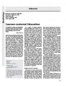
Many modern software development approaches propose a so-called usecase driven process, e.g. the Rational Unified Process RUP, [5]. In these approaches, requirements are analyzed using usecase diagrams and textual scenario descriptions. During the analysis phase these textual scenario descriptions are refined using UML behavior diagrams like sequence diagrams or collaboration diagrams. In the design phase, the program structure is defined using e.g. class diagrams and the program behavior may be modelled using e.g. statecharts. Unfortunately, processes like RUP define only the management aspects of software development. Technical guidance for the actual work and tight tool integration are still missing. Adressing these shortcomings we devloped the Fujaba Development Process (FUP) providing technical guidance for the use of UML diagrams in different development phases and guidance for going from one process phase to the next. To provide optimal tool support for FUP, we extended the Fujaba case tool with an HTML based text document editor with integrated editing of UML diagrams, shown in Figure 1. Thereby, Fujaba provides a project handbook that guides the developers through the development process.
Figure 1: Usecase diagram with scenario for usecase changeSpeed
2.
DOCUMENT STRUCTURE
When a new project is started, Fujaba loads a master copy file that provides an initial structure for the project handbook document. One may modify this initial document in order to adapt it to company or project standards and store the modified document as the new master copy for project handbooks. Similarly, a template description file is loaded, that contains example document fragments for different kinds of UML (diagram) elements. When such an element is added to an UML diagram, the corresponding document fragment is copied into the project handbook. The new fragment is linked to the corresponding diagram element. For each diagram, a pre-defined (and modifiable) anchor describes where template fragments are inserted. The user may modify the template to adapt it to company or project specific needs in the same manner like the other project documents. In the following we describe a possible document structure used in the software development laboratory course of Winter Term 2002 at the University of Kassel.
3.
RUNNING EXAMPLE
The students had to model a game called “Mississippi Queen” using the Fujaba project handbook. In this game, every player has a steamer and has to ship it up the Mississippi collecting passengers. This example was given to the students as an initial example for a development process. Every project starts with a skeleton of a project handbook. First the requirements are collected in usecases. By adding a usecase diagram to the document Fujaba automatically extends the handbook with a chapter for the description of this diagram. Similarly, adding a usecase to a usecase diagram automatically adds a template for the textual description of that usecase to the corresponding description chapter. These textual scenario descriptions have to be filled by the developer. Figure 1 shows a usecase diagram for the Mississippi Queen example and the textual description of a standard scenario for usecase changeSpeed. Our usecase description template defines that each textual usecase description has a paragraph for the start situation, a paragraph for the invocation of that usecase, a number of steps outlining the execution of the usecase and a paragraph for the result situation.
4.
AUTOMATISM
To provide further aid for transition from one process phase to another several automatisms have been introduced, cf. [2] or [3]. One of these derives a so-called story board from the textual scenario description. Initially, this story board is just an activity diagram with one activity for each element of the textual scenario. These activities contain the original textual descriptions as a comment. Now the developer is encouraged to model each step by a collaboration diagram that is embedded in the corresponding story board activity, cf. Figure 2. The first activity of Figure 2 models the start situation of the changeSpeed scenario with a steamer s belonging to player Fred having color green. The developer modelled this situation as an object diagram consisting of a steamer object s, a game object g and an object gui representing the players graphical user interface. The attribute values of the object s are modelled as attribute pre-conditions, saying e.g. that the steamer still has six units of coal.
Figure 3: Class diagram automatically created during story boarding
During creation of story boards all used elements like objects, links, attributes and methods have to be provided with appropriate declarations in an accompanying class dia-
Figure 2: Storyboard for scenario changeSpeed
gram. This already ensures a consistent use of object kinds, attributes, links and methods throughout all scenarios and even within the following design phase. Figure 3 shows the class diagram of the Mississippi Queen example, that has been created during story boarding. Again, adding a class to a class diagram automatically adds a description chapter to the project handbook and adding a method to a class adds a template for the description of this method that usually contains the activity diagram modelling the behavior of this method. Note, method bodies have to be specified, manually. However, in [2] and in [3] we propose a systematic approach for the derivation of method bodies from story boards. In our work presented at [4], this is extended by automatic support for the generation of tests and for the embedding of test protocols into the project handbook.
5.
CONCLUSIONS AND FUTURE WORK
In our approach, the concept of the initial project handbook structure and the automatically applied templates achieve a well structured and uniform project documentation. The approach showed to work well for the students in the software development laboratory course. An idea of a software process was given by the initial structure of the project handbook and was supported continually by the evolving document. This encourages us to specify a detailed software development process inspired by the Rational Unified Process, [5] and Extreme Programming [1] to be implemented as structured project handbooks. The developers can then be aided to apply the process by several automation tasks. In addition, we plan to provide support for team collaboration and for project planning and project management.
6.
REFERENCES
[1] K. Beck. Extreme Programming Explained: Embrace Change. Addison-Wesley Publishing Company, 1999. [2] I. Diethelm, L. Geiger, T. Maier, and A. Z¨ undorf. Turning collaboration diagram strips into storycharts. In Workshop on Scenarios and state machines: models, algorithms, and tools; ICSE 2002. Orlando, Florida, USA, 2002. [3] I. Diethelm, L. Geiger, and A. Z¨ undorf. Uml im unterricht: Systematische objektorientierte probleml¨ osung mit hilfe von szenarien am beispiel der t¨ urme von hanoi. In Erster Workshop der GI-Fachgruppe Didaktik der Informatik. Bommerholz, Germany, 2002. [4] L. Geiger and A. Z¨ undorf. Transforming graph based scenarios into graph transformation based junit tests. In Applications of Graph Transformations with Industrial Relevance (AGTIVE 2003). Charlottesville, Virginia, USA, Septembre 2003. [5] I. Jacobson, G. Booch, and J. Rumbaugh. The Unified Software Development Process. Addison-Wesley Publishing Company, 1999.