12
IEEE TRANSACTIONS ON MICROWAVE THEORY AND TECHNIQUES, VOL. 53, NO. 1, JANUARY 2005
Integrated Interconnect Networks for RF Switch Matrix Applications Mojgan Daneshmand, Student Member, IEEE, Raafat R. Mansour, Fellow, IEEE, Pedram Mousavi, Savio Choi, Bahram Yassini, Andre Zybura, and Ming Yu, Senior Member, IEEE
Abstract—In this paper, two new types of integrated RF interconnect networks are presented. The circuits are printed on double-sided alumina substrates, eliminating the need to use multilayer manufacturing technology. The interconnect networks employ finite ground coplanar lines and vertical transitions and can be easily integrated with semiconductor and microelectromechanical-systems switches. A wide-band 3 3 interconnect network utilizing single and double three-via vertical transitions is investigated theoretically and experimentally. The measured results show a return loss of 20 dB and an isolation of better than 40 dB up to 30 GHz. A vialess double-sided interconnect -band applinetwork is also studied and optimized for satellite cations. This type of interconnect network uses a process requiring only front and back pattern metallization. The measured results indicate a return loss of better than 17 dB and an isolation of better than 45 dB. Index Terms—Microwave integrated circuits (MICs), switch matrix interconnect network.
I. INTRODUCTION
M
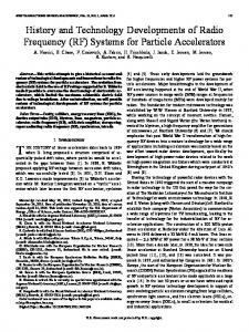
ICROWAVE AND millimeter-wave switch matrices are essential components in telecommunication systems since they enhance satellite capacity by providing full and flexible interconnectivity between the received and transmitted signals. The demand for more advanced switching systems has increased due to the recent growth in multimedia, mobile, and Internet applications. Satellite beam-linking systems vastly rely on switch matrix functionality to manage traffic routing and for optimum utilization of system bandwidth. Fig. 1 shows an example of a satellite payload receiving six different beams from various locations and transferring them to their intended spots. The beam-link system creates sub-channels for each uplink beam where the switch matrix provides the flexibility to independently direct them to the desired downlink channel. Semiconductor and microelectromechanical systems (MEMS) switches are two prominent candidates for realizing such types of switch matrices. The interconnect network, therefore, has to be amenable to integration with these switching Manuscript was received April 21, 2004; revised July 26, 2004. M. Daneshmand and R. R. Mansour are with the Department of Electrical and Computer Engineering, University of Waterloo, Waterloo, ON, Canada N2L 3G1 (e-mail:
[email protected];
[email protected]). P. Mousavi was with the Department of Electrical and Computer Engineering, University of Waterloo, Waterloo, ON, Canada N2L 3G1. He is now with Intelwaves Technologies Ltd., Waterloo, ON, Canada N2L 5R9. S. Choi, B. Yassini, A. Zybura, and M. Yu are with the Research and Development Department, COM DEV Ltd., Cambridge, ON, Canada N1R 7H6. Digital Object Identifier 10.1109/TMTT.2004.839893
Fig. 1.
Switch matrix application in satellite beam-linking network.
elements. Signal transmission and isolation of the interconnect lines are also key factors for the successful design of the switch matrix. By reducing the size and increasing the system density, signal transmission and isolation of the interconnect lines become an important issue. This highlights the fact that there is a need to develop a planar solution for network connectivity. The low-temperature co-fired ceramic (LTCC) technology is a good solution to provide the switch matrix connectivity. The basic materials are ceramic tapes that are fired together at around 900 . It allows the usage of high-conductivity materials such as gold and silver to provide multilayer structures. However, dimensional tolerances are still an issue, especially at high-frequency applications due to material shrinkage during the firing process. The achievable minimum dimensions for the lines and gaps in comparison with those of the conventional ceramic processes are considerably large. The fabrication process for LTCC is also more expensive in comparison with the conventional fabrication processes for microwave integrated circuits (MICs). Thus, a low-cost solution to provide matrix connectivity and maintain precise miniaturized dimensions is greatly desirable. In [1], a brief report is given on a 3 3 interconnect matrix using via vertical transition. In this paper, we expand the concept and present the design details of this interconnect network. We also present another novel configuration to realize a vialess interconnect network for switch matrix applications. The proposed concept eliminates the need for a multilayer manufacturing process and provides an excellent RF performance by using well-established microwave printed circuit technology. The characterization of the interconnect lines and the vertical interconnects are addressed in details. Coupled coplanar waveguide (CPW) vertical transitions are used as basic building blocks to form the interconnect network. A 3 3
0018-9480/$20.00 © 2005 IEEE
DANESHMAND et al.: INTEGRATED INTERCONNECT NETWORKS FOR RF SWITCH MATRIX APPLICATIONS
13
Fig. 2. Schematic of FCG lines printed on both sides of the substrate.
vialess interconnect network has been built and tested to verify the proposed concepts. II. PROPOSED DOUBLE-SIDED INTERCONNECT NETWORK PRINCIPLES One promising solution, using an alumina substrate, is to pattern the main circuit on one side of the substrate and use the other side for crossover transitions. The idea takes advantage of the planar nature of coplanar transmission lines, which makes it possible to reduce parasitic coupling, as well as appropriate layout design and relative placement of the lines, vias, and vertical transitions. When several transmission lines are printed on a common substrate, surface waves and radiation tend to induce parasitic currents on neighboring interconnects and circuits leading to unwanted crosstalk. This parasitic coupling becomes more problematic as circuits are printed on two opposite sides of one substrate. The major advantage of the finite ground coplanar (FGC) and waveguide is that the lowest surface wave mode is leakage occurs at higher frequencies compared to the infinite ground plane CPW line [2]. We use FGC lines to design the entire interconnect circuit. It is believed that due to the nature of the FGC and the thin substrate thickness (10 mil), the surface-wave mode and any additional substrate modes would have no effect on the switch matrix RF performance over the frequency band of interest (up to 30 GHz). In this paper, we study the isolation performance of two parallel and two orthogonal FGC lines. As it is known, increasing the overlapping area of two lines printed on two layers results in higher cross-coupling [3]. Therefore, the two parallel lines structure shown in Fig. 2 is expected to have more coupling than that of two orthogonal lines. To optimize the design, the effect of substrate thickness on the coupling of two parallel lines is investigated. The results of method of moments (MoM) simulation implemented by Sonnet Software1 for the ground strip width of m, central linewidth of m, gap space of m, length mm, and substrate permittivity of 9.8 are shown in Fig. 3(a). As illustrated, the thicker substrate yields less coupling. However, it leads to extra loading of the vertical transitions, which will be discussed later. A 10-mil substrate is a good candidate to obtain a better than 35 dB-isolation up to 30 GHz. 1High Frequency Planar Structure Simulator, Sonnet Software, North Syracuse, NY, 1983–2003. [Online]. Available: http://www.sonnetusa.com/ support/index. asp
Fig. 3. Numerical results for two 50- lines in both sides of the alumina substrate for various: (a) substrate thicknesses and (b) various w + 2s.
Fig. 3(b) illustrates the effect of the center linewidth and gap spacing on the coupling. To obtain this graph, three different 50- lines with various and on a 10-mil alumina equal to 120 m are considered. For substrate with equal to 58, 112, and 184 m, is 32, 64, and 105 m, respec, a better isolatively. Note that, for smaller values of tion is achieved, as the electric field is more confined within the gaps. However, it may increase the insertion loss of the line. To achieve a good isolation while accommodating a reasonable inm and m. For our sertion loss, we selected preliminary design, both MoM implemented by Sonnet and the finite-element method (FEM) realized by HFSS2 confirm that an isolation of better than 35 dB can be achieved. Cross-coupling between two perpendicular FGC lines is also studied. Schematic and FEM simulation results are shown in Fig. 4. The results are obtained for the optimized dimensions m, m, and m on a 10-mil of (254 m) substrate. The isolation between the lines is better than 45 dB for frequencies up to 30 GHz. As expected, the coupling is considerably less than that of parallel lines. The field distribution inside the substrate is also illustrated in this figure. It is evident that the fields of the lines are tightly limited around 2HFSS,
ver. 3.1.04, Ansoft Corporation, Palo Alto, CA, 2002.
14
IEEE TRANSACTIONS ON MICROWAVE THEORY AND TECHNIQUES, VOL. 53, NO. 1, JANUARY 2005
Fig. 4. Two perpendicular FGC lines on opposite sides of the substrate. (a) Schematic. (b) FEM simulation results and electric-field distribution.
the gaps and, thus, the use of smaller gaps results in a better isolation performance. III. BROAD-BAND PLANAR INTERCONNECT NETWORK The main goal here is to introduce a technique to design and fabricate broad-band planar integrated RF switch matrices. It starts by focusing on single and double conducting vertical transitions while minimizing the parasitic coupling. The entire switch matrix architecture, including the vertical transitions, is then investigated. A. Three-Via Vertical Interconnect While the design of vertical transitions in microstrip lines, strip lines, and conventional coplanar lines are well established in literature, very limited research has been reported on vertical transitions of FGC lines [4], [5]. A conceptual schematic of the three-via vertical interconnect is given in Fig. 5. The cylindrical vias form a three-conductor transmission line through the substrate, which minimizes radiation into the substrate. The choice of the via separation and junction dimensions are critical to optimize the performance of the transition.
Fig. 5. (a) Vertical interconnect schematic employing three via-holes and fabricated unit. (b) Measured and simulated S -parameters using the FEM method (HFSS). (c) Electric-field distribution.
For our preliminary interconnect network, the dimensions of the vias in a 10-mil alumina substrate are optimized. They are attached to FGC lines with a signal linewidth of 64 m, spacing between the signal and ground lines of 24 m, and a ground m linewidth of 120 m. The inner vias diameter is and the outer diameters of the via annular ring is 320 m. The via’s diameter is limited to 70% of the substrate thickness, as it is fabricated by laser drilling techniques. The three-via vertical interconnect is matched to 50- FGC lines through an optimized junction. Fig. 5(b) illustrates the HFSS simulation results of the optimized transition. A return loss of better than 30 dB up to 30 GHz has been achieved. To confirm the results, the via are matched to a 50- line on one side and one-port measurement is performed from the other side. The measured return loss agrees
DANESHMAND et al.: INTEGRATED INTERCONNECT NETWORKS FOR RF SWITCH MATRIX APPLICATIONS
15
Fig. 6. (a) Measured and simulated via input impedance. (b) Measured via inductance.
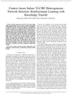
well with that of simulation. Insertion loss of the system is also optimized to better than 0.25 dB up to 30 GHz. As was previously mentioned, the three vias act as a three-conductor transmission line. The electric-field distribution proves this concept, while the field extends from the central line to both outer ground lines. It is well confined between the vias and vanishes at the outside of the outer lines, as shown in Fig. 5(c). Thus, it is expected to have minimum parasitic coupling to neighboring lines. Wide-band modeling of three-via structure is very difficult in terms of RLC discrete elements due to the intertwining and interrelating of the vias, tapered bends, and surrounding transmission lines. In general, the vias are significantly inductive. To get a precise insight, the three-via junction is shorted from one side, while one-port measurement is performed from the other side. The measured input impedance (shown in Fig. 6) indicates that the vias have an inductive effect of approximately 350 pH up to 15 GHz, which increases to 580 pH at higher frequencies. B. Double Three-Via Vertical Interconnect A double three-via transition can be used to establish a crossover for two intersecting FGC lines printed on the same layer, as shown in Fig. 7. The vias penetrate through the substrate and are connected together using a CPW at the backside of the substrate. The total junction is optimized to prevent parasitic interaction of the vias and to minimize the parasitic coupling to the crossing line of the top layer. At the backside, a m, gap space CPW with a central signal linewidth of m, and ground-plane width m is used. Application of the CPW on the backside instead of FGC lines improves the return loss and eliminates the need to use extra tapers at the backside of the substrate.
Fig. 7. (a) Conceptual schematic, (b) fabricated unit, and (c) simulated and measured results of double three-via vertical transition over alumina substrate.
Significant efforts were made to optimize the junction dimensions up to 30 GHz. The sonnet results are shown in Fig. 7(c). FEM analysis (implemented by HFSS) is also used to verify the performance of the double three-via configuration, and the results are illustrated in this figure. In both simulations, the structures are identical, except that in MoM analysis (implemented by Sonnet Software), the thickness of the conductor is ignored, which contributes to a slight deviation in the results of the two electromagnetic (EM) simulators. The insertion loss is less than 0.5 dB at 30 GHz, and approximately 0.25 dB of the overall loss can be attributed to loss of the two three-via vertical interconnects. The parasitic coupling of the transition on the top crossing line is expected to be better than 45 dB, as shown in Fig. 7(c).
16
IEEE TRANSACTIONS ON MICROWAVE THEORY AND TECHNIQUES, VOL. 53, NO. 1, JANUARY 2005
N2N
Fig. 8. (a) Small matrix as building block. (b) Bigger networks composed of several small building blocks (three-stage Clos rearrangeable interconnect network [7]). Fig. 9. (a) Schematic and (b) fabricated structure of our proposed double-sided network for 3 3 switch matrix.
2
A comparison of these results with those shown in Fig. 4 proves that the double three-vias interconnect does not add extra parasitic coupling to the other line. The proposed double three-via structure is fabricated over an alumina substrate and gold coating of 3.5 m, as shown in Fig. 7(b). Two-port -parameter measurement is performed, and the results are shown in Fig. 7(c). It is observed that the measured data agrees well with that of the simulation. It shows better than 30 dB return loss up to 25 GHz. The insertion loss is 0.5, as was predicted. The isolation of the two double-via structures with the crossing line is better than 45 dB. C. Switch Matrices Interconnect Architecture In conventional systems, switch matrices are used to provide a connection between a set of inputs and a set of outputs through the switch elements and a set of signal paths. One approach, for connecting input ports to output ports, is to use single-pole -throw (SPNT) switches and make pairwise connections between every input and output switch, as shown in Fig. 8(a). Although the concept can be theoretically used for any size switch matrix, in practical applications, small matrices are employed as basic building blocks to create larger structures. There are several topologies that can be used in this regard [6], [7]. Fig. 8(b) shows a Clos interconnect network that is made of several building blocks to form an matrix [7]. It is a rearrangeable network that has the capability of connecting any input to any output, while one or more existing links may need to be rearranged for each new set of connections. Our objective is to build an switch matrix (with as large as the technology allows) to be used as the building block
for the large switch matrices. To verify the idea of double-sided architecture, an interconnect circuit for a basic building block is designed and fabricated. As shown in Fig. 9, the of main circuit is patterned on the topside of the substrate, while the backside is used for crossover transitions. This configuration utilizes nine lines connecting three single-pole 3-throw (SP3T) switches at the input to three other SP3T switches at the outputs. One should note that, in any given state, only three of these lines are carrying RF signal. Throughout the design, an effort is made to have the maximum distance between the lines carrying signal to reduce unwanted couplings. For instance, two adjacent lines from two neighboring switches that may carry signal simultaneously are patterned in two different layers to increase the pitch in between. m, m, and The lines are 50- FGC with m on a 10-mil (254 m) substrate. The previously optimized dimensions of the vertical interconnects are used for signal lines connection from one side to the other. To predict the interconnect lines performance, they are subdivided and analyzed using full-wave techniques and then linked through net list coding. All the lines are optimized to have less than 20-dB return loss up to 30 GHz and an isolation of better than 40 dB. This structure is fabricated using a gold-coated alumina substrate, as shown in Fig. 9. The return and insertion losses of all the lines are measured and are shown in Fig. 10(a). All the lines show a return loss of better than 20 dB up to 30 GHz. Overall, the interconnect lines without back-layer transition show a
DANESHMAND et al.: INTEGRATED INTERCONNECT NETWORKS FOR RF SWITCH MATRIX APPLICATIONS
17
Fig. 10. Measured S -parameters of the interconnect network shown in Fig. 9. (a) Return and insertion losses. (b) Isolation.
0.5-dB loss at 15 GHz and 1-dB loss at 30 GHz, while two vias of back-transitions together add 0.5 dB to these values. These results agree well with those predicted. The isolation between the lines is also measured and is shown in Fig. 10(b). For measurement purposes, the lines are matched to 50- thin-film resistors. The isolation of approximately 40 dB is measured between any two interconnect lines. IV. VIALESS PLANAR INTERCONNECT NETWORK In spite of the fact that the proposed interconnect network demonstrates an extremely good performance, eliminating the vias is always beneficial. This not only further simplifies the fabrication process, but also increases the production yield. Temperature variation and aging of the circuit may also generate some cracks on the vias, resulting in some difficulties in full functionality of the system. In order to solve these problems, we introduce another new interconnect network. In this technique, the vias are eliminated and the entire network is fabricated simply by frontside and backside metallization. This technique is fully compatible with MIC and MEMS fabrication
Fig. 11. Vertical coupled CPW transition. (a) schematic. (b) Fabricated unit. (c) Simulated S -parameters.
Conceptual
techniques and can be easily integrated with solid-state and MEMS switches [8]. A. Coupled CPW Vertical Interconnect In this technique, a double-sided coupled CPW interconnect substitutes the three-via transitions. It consists of an overlay of two FGC lines at each side of the substrate, while EM coupling transfers the RF signal from one side to the other [10], [11]. Although the feeding FGC lines carry only the even mode, this transition supports both even and odd modes. The dimensions of the overlay region are designed so that the even- and odd-mode impedances produce a perfect match at the frequency -long tranof interest. This results in a quarter-wavelength sition, which is shown in Fig. 11(a). For the 10-mil alumina , the signal linewidth is m substrate with
18
IEEE TRANSACTIONS ON MICROWAVE THEORY AND TECHNIQUES, VOL. 53, NO. 1, JANUARY 2005
Fig. 12. Double vertical coupled FGC transitions. (a) Conceptual schematic. (b) Fabricated unite from top view. Fig. 13.
Measured results for the vertical coupled CPW interconnect.
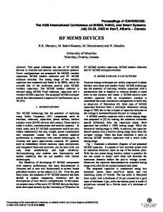
and the ground linewidth is m. The spacing between the central line and ground planes is one of the most effective parameters in controlling the coupling factor, which is m. This factor increases by enlarging the substrate thickness. The vertical CPW coupled interconnects are matched to 50- FGC lines through an optimized junction. A full-wave analysis using HFSS is performed to optimize -band and the results are shown the transition for satellite in Fig. 11(c). They indicate a return loss of better than 20 dB between 11–14 GHz. The insertion loss is approximately 0.5 dB, which includes conductor loss and parasitic radiation. Discrete RLC modeling of such a transition is not simple due to lots of interactions in between the lines. Overall, in our frequency range of interest, the common area of the top and back lines creates a large capacitor that couples the top circuit to the backside. By enlarging the overlay area, the capacitance increases, which leads to a better signal coupling. B. Double Coupled CPW Vertical Interconnect In this circuit, the backside of the substrate is used for the crossovers. Double coupled CPW vertical interconnect is utilized to couple the RF signal from the topside of the substrate to the back lines and, after the crossover, transfer it again to the top layer. A conceptual schematic of this transition is shown in Fig. 12(a). A significant effort is made to optimize the performance and prevent any interaction between the vertical coupled interconnects. The parasitic coupling of the coupled CPW lines to the top layer crossing line is also minimized. Each vertical coupled transition individually is similar to that shown in Fig. 11(a). They are connected together by an FGC with a signal linewidth of m, spacing of m, and the ground linewidth of m. Full-wave analysis using HFSS is applied to design the transitions. The optimized distance of 1200 m between the vertical transitions results in an isolation of better than 40 dB with the crossing line. To verify the idea, the vertical coupled FGC transition shown in Fig. 12(b) is fabricated over a double-sided 10-mil alumina substrate with gold coating of 4 m. A two-port on-wafer probe measurement is performed, and the results are
Fig. 14. (a) Conceptual schematic. (b) Fabricated unit of our proposed vialess interconnect network.
demonstrated in Fig. 13. It can be seen that a return loss of better than 15 dB is obtained over 9.5–13 GHz. The measured insertion loss is close to 0.6 dB, while the measured isolation is over 40 dB. C. Switch Matrix Interconnect Architecture When several coupled CPW interconnects are printed on a common substrate, EM waves may induce extra parasitic coupling to the other transitions. This issue may become more prob-
DANESHMAND et al.: INTEGRATED INTERCONNECT NETWORKS FOR RF SWITCH MATRIX APPLICATIONS
Fig. 16. Conceptual layout of switch matrix building blocks of: (a) 3 (b) 9 9.
2
Fig. 15. Measured results for the proposed interconnect network shown in Fig. 14. (a) Return and insertion losses. (b) Isolation.
lematic when they are placed in a double-sided network with several transmission lines. To verify this, a 3 3 switch matrix interconnect network is investigated. Fig. 14 shows the entire interconnect network schematic, which includes the top lines and back crossovers. It is designed based on pairwise connection for a 3 3 switch matrix. This structure is 1.7 cm 1.8 cm and can be easily integrated with CPW SP3T switches [8]. By avoiding the vias in this configuration, it is well suited for high-yield mass production. The FGC lines are designed to be 50 with signal linewidth of m, spacing of m, and the ground linewidth of m. The transition shown in Fig. 11(a) is used to transfer the RF signals from one surface to the other side. For abrupt crossovers, double CPW coupled vertical transition is used. To optimize the entire system, it is divided into several subsections and analyzed using an EM simulator. The results are
19
2 3 and
then linked together using netlist coding. The optimized configuration is fabricated over a 10-mil gold-coated alumina substrate and is shown in Fig. 14(b). A two-port on-wafer probe measurement is performed to evaluate the interconnect network performance, and the results are shown in Fig. 15. For the frequency range of 12–13 GHz, the measured results of all the lines show a return loss of better than 20 dB, except for line III, which is 17 dB. The insertion loss of the top lines is approximately 0.9 dB, which is increased by approximately 0.6 dB for each crossover. The measured results [see Fig. 15(b)] show that an isolation of 45 dB is obtained over the band of interest. V. SWITCH MATRIX INTEGRATION The proposed networks integration with the SP3T solid-state or MEMS switches results in switch matrices. A layout of a 3 3 switch matrix based on the proposed broad-band planar interconnect network is shown in Fig. 16(a). The switches can be incorporated using wire-bonding or flip-chip technology [8]–[12]. Additionally, MEMS switches can be fabricated monolithically with the interconnect networks. The proposed interconnect networks can be packaged and used as basic building blocks for larger structures. Alternatively, Clos network [13], [14] can be used to expand them to bigger structures over one common substrate. For instance, a 9 9 matrix conceptual layout based on the proposed broad-band planar interconnect architecture and 3 3 matrix building blocks is shown in Fig. 16(b).
20
IEEE TRANSACTIONS ON MICROWAVE THEORY AND TECHNIQUES, VOL. 53, NO. 1, JANUARY 2005
VI. CONCLUSION This paper has presented two new planar double-sided interconnect networks using conventional microwave printed circuit technology. The networks employ FGC lines integrated with vertical transitions. A wide-band network based on single and double vertical three-via interconnect junctions is presented and optimized to provide a return loss of better than 20 dB up to 30 GHz and an isolation of better than 40 dB. In addition, another novel interconnect network is introduced that utilizes FGC lines and single and double coupled CPW vertical transitions. Both types of transitions have been investigated both theoretically and experimentally. Two 3 3 interconnect networks have been fabricated and measured. The measured results for the individual transitions and for the whole interconnect networks have demonstrated the validity of the concepts proposed in this paper.
REFERENCES [1] M. Daneshmand, R. R. Mansour, P. Mousavi, S. Choi, B. Yassini, A. Zybura, and M. Yu, “A novel integrated interconnect network for RF switch matrix applications,” in IEEE MTT-S Int. Microwave Symp. Dig., Jun. 2004, pp. 1211–1214. [2] M. Tsuji, H. Shigesawa, and A. A. Oliner, “New interesting leakage behavior on coplanar waveguides of finite and infinite widths,” IEEE Trans. Microw Theory Tech., vol. 39, no. 12, pp. 2130–2137, Dec. 1991. [3] A. Margomenos, K. J. Herrick, M. I. Herman, S. Valas, and L. P. B. Katehi, “Isolation in three-dimensional integrated circuits,” IEEE Trans. Microw. Theory Tech., vol. 51, pp. 25–32, Jan. 2003. [4] R. N. Simons, R. Q. Lee, K. A. Shalkhauser, J. Owens, J. Demarco, J. Leen, and D. Sturzebecher, “Finite width coplanar waveguide patch antenna with vertical fed through interconnect,” in IEEE AP-S and URSI Radio Science Meeting Dig., vol. 2, 1996, pp. 1138–1341. [5] K. J. Herrick, J. G. Yook, and L. P. B. Katehi, “Microtechnology in the development of three-dimensional circuits,” IEEE Trans. Microw. Theory Tech., vol. 46, no. 11, pp. 1832–1844, Nov. 1998. [6] H. S. Hintor, An Introduction to Photonic Switching Fabrics. New York: Plenum, 1993. [7] H. Y. Lee, F. K. Hwang, and J. D. Carpinelli, “A new decomposition algorithm for rearrangeable Clos interconnection networks,” IEEE Trans. Commun., vol. 44, no. 11, pp. 1572–1578, Nov. 1996. [8] M. Daneshmand and R. R. Mansour, “Fabrication and modeling of an SP3T RF MEMS switch,” in IEEE AP-S and URSI Radio Science Meeting Dig., vol. 1, 2003, pp. 391–394. [9] J. J. Yao and M. F. Chang, “A surface micromachined miniature switch for telecommunications applications with signal frequencies from DC up to 4 GHz,” presented at the 8th Int. Solid-State Sensors and Actuators Conf., 1995. [10] R. W. Jackson and D. W. Matolak, “Surface to surface transition via electromagnetic coupling of coplanar waveguide,” IEEE Trans. Microw. Theory Tech., vol. MTT-35, no. 11, pp. 1027–1032, Nov. 1987. [11] J. P. Raskin, G. Gauthier, L. P. Katehi, and G. M. Rebeiz, “ -band single-layer vertical transition,” IEEE Trans. Microw. Theory Tech., vol. 48, no. 1, pp. 161–164, Jan. 2000. [12] V. Milanovic, M. Maharbiz, and K. S. J. Pister, “Batch transfer integration of RF microrelays,” IEEE Microw. Guided Wave Lett., vol. 10, no. 8, pp. 313–315, Aug. 2000. [13] H. Y. Lee, F. K. Hwang, and J. D. Carpinelli, “A new decomposition algorithm for rearrangeable Clos interconnection networks,” IEEE Trans. Commun., vol. 44, no. 11, pp. 1572–1578, Nov. 1996. [14] F. K. Hwang, “Control algorithms for rearrangeable Clos networks,” IEEE Trans. Commun., vol. COM-31, no. 8, pp. 952–954, Aug. 1983.
W
Mojgan Daneshmand (S’00) received the B.Sc. degree in electrical engineering from the Iran University of Science and Technology (IUST), Tehran, Iran, in 1999, the M.Sc. degree in electrical engineering from the University of Manitoba, Winnipeg, MB, Canada, in 2001, and is currently working toward the Ph.D. degree at the University of Waterloo, Waterloo, ON, Canada. She is currently with the Center for Integrated RF Engineering (CIRFE) Laboratory, University of Waterloo, where she is involved with RF MEMS device fabrication and characterization and microwave/antenna circuits. She has authored or coauthored several scientific papers. She has a patent pending in the area of RF MEMS switches. Ms. Daneshmand currently holds Natural Sciences and Engineering Research Council of Canada (NSERC) and Canadian Space Agency scholarships.
Raafat R. Mansour (S’84–M’86–SM’90–F’01) was born in Cairo, Egypt, on March 31, 1955. He received the B.Sc. (with honors) and M.Sc. degrees from Ain Shams University, Cairo, Egypt, in 1977 and 1981, respectively, and the Ph.D. degree from the University of Waterloo, Waterloo, ON, Canada, in 1986, all in electrical engineering. In 1981, he was a Research Fellow with the Laboratoire d’Electromagnetisme, Institut National Polytechnique, Grenoble, France. From 1983 to 1986, he was a Research and Teaching Assistant with the Department of Electrical Engineering, University of Waterloo. In 1986, he joined COM DEV Ltd., Cambridge, ON, Canada, where he held several technical and management positions with the Corporate Research and Development Department. In 1998, he became a Scientist. In January 2000, he joined the University of Waterloo, as a Professor with the Department of Electrical and Computer Engineering. He holds an NSERC Industrial Research Chair in RF engineering with the University of Waterloo. He has authored or coauthored numerous publications in the areas of filters and multiplexers and high-temperature superconductivity. He holds several patents related to microwave filter design for satellite applications. His current research interests include superconductive technology, MEMS technology, and computer-aided design (CAD) of RF circuits for wireless and satellite applications.
Pedram Mousavi received the B.Sc. (Hons.) degree in telecommunication engineering from the Iran University of Science and Technology, Tehran, Iran, in 1995, and the M.Sc. and Ph.D. degrees from the University of Manitoba, Winnipeg, MB, Canada, in 1997 and 2000, respectively, all in electrical engineering. From 2001 to 2003, he was an RF Integrated Circuits Designer with the Sirific Wireless Corporation. From 2003 to 2004, he was a Post-Doctoral Fellow with the Department of Electrical and Computer Engineering, University of Waterloo, Waterloo, ON, Canada, where he was involved with RF MEMS phase shifters. He is a co-founder and Director of Intelwaves Technologies Ltd., Waterloo, ON, Canada, which specializes in ultra low profile mobile satellite terminals. His research interest includes applied electromagnetics, antennas design, and high-frequency integrated circuits.
DANESHMAND et al.: INTEGRATED INTERCONNECT NETWORKS FOR RF SWITCH MATRIX APPLICATIONS
Savio Choi received the B.Sc. degree in electrical and electronic engineering, University of Birmingham, Birmingham, U.K., in 1982, and the M.Sc. degree in microwave and modern optics from University College London, London, U.K., in 1985. From 1982 to 1989, he was with Marconi Space Systems Ltd., Stanmore, Middlesex, U.K., where he designed filters multiplexers for satellite and military applications. In 1989, he joined COM DEV Ltd., Cambridge, ON, Canada, where he continued his career in passive microwave equipment design and development for satellite applications. In 2000, he joined the Research and Development Department, COM DEV Ltd., where his research and development efforts have focused on MEMS technology and applications. He has authored or coauthored numerous technical papers concerning microwave filters and RF MEMS technology.
Bahram Yassini received the M.A.Sc. degree in electrical engineering from the University of Waterloo, Waterloo, ON, Canada in 2001. In 2001, he joined the Research and Development Department, COM DEV Ltd., Cambridge, ON, Canada, where he has been involved in the design and modeling of MEMS switches, LTCC interconnects, and low-noise amplifier (LNA) circuits for space applications. Prior to that, he was with Algorex Canada, where he was involved with RF/wireless channel modeling as an RF Engineer, Italtel SPA, where he was involved with digital radio networks as a Senior Technical Advisor, and MATN, where he was involved with wireless and satellite communication systems as a Senior Radio System Engineer. His main research interests include the design and optimization of passive and active microwave circuits, particularly MEMS, LTCC interconnect circuits, and LNAs.
21
Andre Zybura received the M.Sc. degree in mechanical engineering and production (with a specialization in material engineering) from Warsaw Technical University, Warsaw, Poland, in 1977. In 1987, he joined COM DEV Ltd., Cambridge, ON, Canada, where he has been involved with materials and processes engineering for Design Assurance, Corporate Research and Development, and recently for Design Integrity supporting the Switch Department. He has developed and qualified several manufacturing and assembly processes, and has been involved with the improvement of switch manufacturing yield. He has coauthored several publications on novel magnetic materials, dimensional stability of aluminum alloys, RF MEMS switch applications, and physics of contacts. He holds three patents.
Ming Yu (S’90–M’93–SM’01) received the Ph.D. degree in electrical engineering from the University of Victoria, Victoria, BC, Canada, in 1995. In 1993, while working on his doctoral dissertation part time, he joined COM DEV Ltd., Cambridge, ON, Canada, as a Member of Technical Staff. He was involved in designing passive microwave/RF hardware from 300 MHz to 60 GHz. He was also a principal developer of a variety of COM DEV Ltd.’s proprietary software for microwave filters and multiplexers. His varied experience also includes being the Manager of Filter/Multiplexer Technology (Space Group) and Staff Scientist of Corporate Research and Development. He is currently the Director of Research and Development, COM DEV Ltd., where he is responsible for overseeing the development of RF MEMS technology, computer-aided tuning, and EM modeling and optimization of microwave filters/multiplexers for wireless applications. He is also an Adjunct Associate Professor with the University of Waterloo, Waterloo, ON, Canada. He has authored or coauthored over 30 publications. He has also authored numerous proprietary reports. He holds two U.S. patents with three patents pending. Dr. Yu is a member of IEEE Technical Coordinating Committee (TCC, MTT-8). He is a frequent reviewer for numerous IEEE and Institution of Electrical Engineers (IEE), U.K. publications. He was the recipient of the 1995 COM DEV Achievement Award for the development of a computer-aided tuning (CAT) system for microwave filters and multiplexers.