Integration and Circuit Demonstration of Chalcogenide Memory Elements with a Radiation Hardened CMOS Technology J. Maimon Ovonyx, Inc. 8665 Sudley Rd., #263 Manassas, VA 20110
[email protected]
K. Hunt AFRL 3550 Aberdeen Ave. SE, Bldg. 891
Kirtland AFB, NM 87117-5776
[email protected]
Abstract – BAE SYSTEMS in Manassas, Virginia, and Ovonyx, Inc., have previously reported electrical test results from stand-alone single-bit chalcogenide memories. In this paper we present a description of two test chips, one that has been used to integrate the chalcogenide memory element with BAE SYSTEMS’ radiation hardened 0.5 µm CMOS technology, and another to develop 64 kbit arrays with full write-read circuitry suitable for environmental and radiation testing. Electrical test results from these test chips will be presented showing full functionality.
J. Rodgers, L. Burcin, K. Knowles BAE SYSTEMS 9300 Wellington Rd Manassas, VA 20110
[email protected]
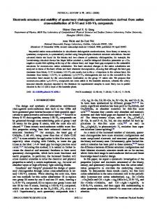
The two structural states of the chalcogenide alloy, as shown in Figure 1, are an amorphous state and a polycrystalline state. Relative to the amorphous state, the polycrystalline state shows a dramatic increase in free electron density, similar to a metal. This difference in free electron density gives rise to a difference in reflectivity and resistivity. In the case of the re-writeable CD and DVD disk technology, a laser is used to heat the material to change states. The state of the memory is read by directing a low-power laser at the material and detecting the difference in reflectivity between the two phases.
TABLE OF CONTENTS 1. 2. 3. 4.
INTRODUCTION INTEGRATION WITH CMOS CIRCUIT DEMONSTRATION SUMMARY
1. INTRODUCTION The term “chalcogen” refers to the Group VI elements of the periodic table. “Chalcogenide” refers to alloys containing at least one of these elements such as the alloy of germanium, antimony, and tellurium discussed here1-4. Energy Conversion Devices, Inc., has used this particular alloy to develop a phase-change memory technology used in commercially available rewriteable CD and DVD disks5-14. This phasechange technology uses a thermally activated, rapid, reversible change in the structure of the alloy to store data. Since the binary information is represented by two different phases of the material it is inherently non-volatile, requiring no energy to keep the material in either of its two stable structural states.
1
Figure 1. Transmission Electron Microscope images of the two phases of a GeSbTe alloy
Ovonyx, Inc., under license from Energy Conversion Devices, Inc., is working with several commercial partners to develop a solid-state nonvolatile memory technology using the chalcogenide phase change material15-18. To implement a memory the device is incorporated as a two terminal resistor element with standard CMOS processing. Resistive heating is used to change the phase of the chalcogenide material. Depending upon the temperature profile applied, the material is either melted by taking it above the melting temperature (Tm) to form the amorphous state, or crystallized by holding it at a lower temperature (Tx) for a slightly longer period of time, as shown in Figure 2. The time needed to
program either state is ≤ 400ns. Multiple resistance states between these two extremes have been demonstrated, enabling multi-bit storage per memory cell. However, current development activities are focused on single-bit applications. Once programmed, the memory state of the cell is determined by reading its resistance.
and has no impact on device wear out (unlimited read cycles).
2. INTEGRATION WITH CMOS Under contract to the Space Vehicles Directorate of the Air Force Research Laboratory (AFRL), BAE SYSTEMS and Ovonyx began the current program in August of 2001 to integrate the chalcogenide-based memory element into a radiation-hardened CMOS process. The initial goal of this effort was to develop the processes necessary to connect the memory element to CMOS transistors and metal wiring, without degrading the operation of either the memory elements or the transistors. It also was desired to maximize the potential memory density of the technology by placing the memory element
Figure 2. Chacogenide Programming
Since the data in a chalcogenide memory element is stored as a structural phase rather than an electrical charge or state, it is expected to be impervious to ionizing radiation effects19. This inherent radiation tolerance of the chalcogenide material and demonstrated write speeds more than 1000 times faster than commercially available nonvolatile memories make it attractive for spacebased applications. A radiation hardened semiconductor technology incorporating chalcogenidebased memory elements will address both critical and enabling space system needs, including standalone memory modules and embedded cores for microprocessors and ASICs.
Metal 1
W Stud
Top Electrode Chalcogenide Bottom Electrode Transistor
Figure 3. Chalcogenide Memory Element Integrated with Transistor (Simplified)
Previously, BAE SYSTEMS and Ovonyx have reported on the results of discrete memory elements fabricated in BAE SYSTEMS’ Manassas, Virginia facility17,18. These devices were manufactured using standard semiconductor process equipment to sputter and etch the chalcogenide material. While built in the same line used to fabricate radiation-hardened CMOS products, these memory elements were not yet integrated with transistors. They were discrete two-terminal programmable resistors, requiring approximately 0.6 mA to set the device into a low resistance state, and 1.3 mA to reset it to the high resistance state. One billion (1E9) write cycles between these two states were demonstrated. Reading the state of the device is non-destructive
directly above the transistors and below the first level of metal as shown in a simplified diagram in Figure 3. To accomplish this process integration task, it was necessary to design a test chip with appropriate structures. This vehicle was called the Access Device Test Chip (ADTC) since each memory cell requires an access device (transistor) in addition to the chalcogenide memory element. Such a memory cell, comprised of one access transistor and one chalcogenide resistor, is herein referred to as a 1T1R cell.
2
The ADTC included 272 macros, each with 2 columns of 10 probe pads. Of these, 163 macros were borrowed from existing BAE SYSTEMS’ test structures and used to verify normal transistor operation. There were 109 new macros designed to address the memory element features. These included sheet resistance and contact resistance measurement structures, discrete memory elements of various sizes and configurations, and two 16-bit 1T1R memory arrays.
(RDYNAMIC) of ≈1kΩ. In itself, this transition to a low resistance electrical state does not change the structural phase of the material. However, it does allow for heating of the material to program it to the low resistance state (1) or the high resistance state (0). Extrapolation of the portion of the I-V curve that is above VT to the X-axis yields a point referred to as a holding voltage (VH). The applied voltage must be reduced below VH to exit the programming mode.
Short loop (partial flow) experiments were processed using subsets of the full ADTC mask set. These experiments were used to optimize the process steps used to connect the bottom electrode of the memory element to underlying tungsten studs and to connect an additional tungsten stud level between Metal 1 and the top electrode of the memory element. A full flow experiment was then processed to demonstrate integrated transistors and memory elements.
Figure 5 shows the operation of a 1T1R memory, again with the access transistor biased on. The plotted resistance values were measured below VT, while the current used to program these resistances were measured above VT. Similar to the previously demonstrated stand-alone memory elements, these devices require approximately 0.6 mA to set to the low resistance state (RSET) and 1.2 mA to reset to the high resistance state (RRESET). The circuit was verified to be electrically open with the access transistor biased off.
Figure 4 shows the I-V characteristic for a 1T1R memory cell successfully fabricated using the ADTC vehicle. The voltage is applied to one of the two terminals of the chalcogenide resistor, and the access transistor (biased on) is between the other resistor terminal and ground. The high resistance amorphous material shows very little current below a threshold voltage (VT) of 1.2V. In this same region the low resistance polycrystalline material shows a significantly higher current. The state of the memory cell is read using the difference in I-V characteristics below VT. Above VT, both materials display identical I-V characteristics, with a dynamic resistance Read Range
VH: 0.5V
Write 1
Resistance (Ohms)
0
RDYNAMIC: 1KΩ VT: 1.2V
1
1.5
0
1
2
3
4
Gate Voltage (V)
2.5
Voltage (V) Polycrsytalline
1.5
1.E+00 1.E-02 1.E-04 1.E-06 1.E-08 1.E-10 1.E-12 -1
2
1
Figure 5. Resistance vs. Programming Current of Chalcogenide Memory Element through Access Transistor (Biased On)
0.0 0.5
0.5 Current (mA)
0.5
0
1.E+04 Polycrystalline
Write 0
1.0
1.E+05
1.E+03
Program Range
1.5 Current (mA)
Amorphous
Drain Current (A) .
2.0
1.E+06
Pre-Rad
Post 2MRad
Amorphous
Figure 6. Total Dose (X-Ray) Response of N-Channel Transistor Integrated with Chalcogenide Memory
Figure 4. I-V Characteristic of 1T1R Cell, with Transistor Biased On
3
cause excessive read settling time when more than 16 columns were connected to a sense amp. Each column has its own write current driver, which also performs the column select function for write operations.
Figure 6 shows the total dose (X-ray) response of N-channel transistors processed through the chalcogenide memory flow. The small threshold voltage shift is typical of BAE SYSTEMS’ standard radiation-hardened transistor processing. All other measured parameters (drive current, threshold voltage, electrical channel length, contact resistance, etc.) were also typical of product manufactured without the memory element.
The single-ended sense amplifier reads the current drawn by a single cell when a voltage is applied to
3. CIRCUIT DEMONSTRATION In order to test the behavior of our chalcogenide cells as circuit elements, we developed the Chalcogenide Technology Characterization Vehicle (CTCV). The CTCV contains a variety of memory arrays with different architecture, circuit, and layout variations. Key goals in the design of the CTCV were: 1) to make the read and write circuits robust with respect to potential variations in cell electrical characteristics; 2) to test the effect of the memory cell layout on performance; and 3) to maximize the amount of useful data obtained that could later be used for product design.
Conservative FET cell
Aggressive FET cell
Single-Ended Sense Amp
Single-Ended Sense Amp
Conservative FET cell
Aggressive FET cell
Differential Sense Amp
Differential Sense Amp
Process Monitor Circuits Figure 7. Contents of One of the Four CTCV Chiplets.
The CTCV was sub-divided into four chiplets, each containing variations of 1T1R cell memory arrays and various standalone subcircuits. Standalone copies of the array subcircuits were included in each chiplet for process monitoring and read/write current experiments.
it. The differential amplifier measures the currents in two selected cells that have previously been written with complementary data, and senses the difference in current between them. This cuts the available memory size in half, but increases noise margin and sensitivity. In both the single-ended and differential sense amplifiers, a voltage limiting circuit prevents the chalcogenide element voltage from exceeding VT, so that the cell is not inadvertently re-programmed.
A diagram of one of the chiplets is shown in Figure 7. The arrays all contain 64k 1T1R cells, arranged as 256 rows by 256 columns. This is large enough to make meaningful analyses of parasitic capacitance effects, while still permitting four variations of the array to be placed on each chiplet. The primary differences between arrays consist of the type of sense amp (single-ended or differential) and variations in the location and number of contacts in the memory cell.
On one chiplet, there are two arrays designed without sense amplifiers. Instead, the selected column outputs are routed directly to the 16 I/O pins where the data outputs would normally be connected. This enables direct analog measurements to be made on a selected cell. A third array on this chiplet has both the column select switches and the sense amplifiers deleted. Eight of the 256 columns are brought out to I/O pins. This enables further analog measurements to be made, without an intervening column select transistor.
The data in the single-ended arrays is formatted as 4096 16-bit words (64k bits), and in the differential arrays as 4096 8-bit words (32k bits). The 256 columns are divided into 16 groups of 16. One sense amplifier services each group, and the 16 columns in each group are selected one at a time based on the four most significant address bits. In simulations, stray capacitance was predicted to 4
“Conservative” and “aggressive” layout versions of the chalcogenide cell were made. The conservative cell is larger, and has four contacts to bring current through to the bottom and top electrodes of the memory cell. The aggressive cell contains only two contacts per electrode, reducing its size. The pitch of the larger cell was used to establish row and column spacing in all arrays. The aggressive cell could thus be easily substituted for the conservative cell. Short wires were added to the smaller cell to map its connection points to those of the larger. This permitted testing both cells in one array layout without requiring significant additional layout labor. A final variation in the cell design involved contact spacing. The contacts on the bottom electrode were moved to be either closer to or farther away from the chalcogenide "pore." This allows assessment of the effect of contact spacing on the thermal and electrical characteristics of the chalcogenide pore.
Figure 8. Wirebond Packaged CTCV Chip 1 Die
For the read circuit, several cell resistance sensing schemes were investigated during CTCV development. The adopted scheme applies a controlled voltage to the cell to be read, and the resulting current is measured. Care is taken not to exceed VT during a read cycle. The sense amplifier reflects the read current into a programmable NFET load, thus generating a high (1) or low (0) output. The gate bias of all sense amplifier loads can be varied in parallel to change the current level at which the output voltage switches. The bias levels are calibrated via a standalone copy of the read circuit that has all key nodes brought out to pins. The NFET load's output is buffered by a string of CMOS inverters to provide full CMOS logic voltage swing, and then routed to the correct data output I/O pad driver.
Process monitoring structures were included on each chiplet to aid in calibration of memory array test data. These consist of a standalone replica of each of the Write and Read (single-ended) circuits, a CMOS inverter, and a 1T1R cell. The outputs of each of these circuits were brought out to permit measurement of currents versus bias voltages. Pins were provided on the CTCV for external bias voltage inputs to vary the read and write current levels. The standalone copies of the read/write circuits are provided with all key nodes brought out to pins. These replica circuits permit the read and write currents to be programmed by varying the bias voltages. This allows more in-depth characterization to be performed in advance of designing a product. In an actual product, bias voltages would be generated by on-chip reference circuits.
When a read circuit supplies a current to a selected cell, the cell's corresponding column charges up toward the steady state read voltage. The column voltage waveform is affected by the programmed resistance and internal capacitances of each of the cells in the column, and thus is pattern dependent. The combined charge from all of the column's cells during this charging process may travel into the sense amplifier input, momentarily causing it to experience a transient, which could prevent the accessed cells’ data from being read correctly. To minimize this effect, each column is discharged after a write, and precharged before a read.
In the write circuit, a PFET driver is connected to each column, and is normally turned off by setting its gate bias to Vdd. When a write is to occur, the selected driver’s gate is switched to one of two external bias voltages for the required write pulse time. The bias voltages can be calibrated to set the write drive currents to the levels needed to reliably write a one or a zero. The data inputs determine which bias voltage is applied to each write driver. 5
A family of drive current vs. bias voltage curves was constructed for both on-chip programming drive circuits across various values of RDYNAMIC. See Figures 9 and 10. These curves validate design simulations and demonstrate adequate operating range of each of the circuits.
Transistor parametric and discrete memory element test structures were tested on the CTCV lot at the wafer level. These tests served two purposes. The first goal was to confirm that the extra processing steps involved in inserting the chalcogenide flow had no effect on the base CMOS technology. No statistical differences in transistor parametric values were noted between these wafers and standard 0.5µm RHCMOS product.
3.00E-03
The second goal of wafer test was to measure the set, reset and dynamic programming resistances (RSET, RRESET and RDYNAMIC), threshold and holding voltages (VT and VH), and required programming currents (ISET and IRESET) of stand-alone, twoterminal chalcogenide memory elements. These values were used to set the operating points of the write driver circuits and the bias point of the sense amp.
RDYNAMIC
Drive current
2.50E-03
200 Ω 300 Ω
2.00E-03
400 Ω 500 Ω
1.50E-03
600 Ω
1.00E-03
700 Ω 900 Ω
5.00E-04
1500 Ω
0.00E+00 0
0.5
1
1.5
2
2.5
3
3.5
Vb1 bias voltage
Figure 9. Program “1” drive current for various values of RDYNAMIC
To allow debug of the CTCV module test setup in parallel with the wafer test effort, one wafer was selected and diced to remove the CTCV die. Five die of one of the four chiplets, (chip 1) were sent ahead through the packaging process. See Figure 8. Chip 1 has four different array configurations, two 64 kbit, single ended sense amp arrays and two 32 kbit, differential sense amp arrays. Two of the arrays were constructed with the conservative cell layout and two with the aggressive cell layout. Functional test patterns used on these send-ahead devices included all zeros, all ones, checkerboard and checkerboard bar. The results of this testing showed that all circuit functional blocks (control circuits, addressing, data I/O, write 0/1, and sense amp) performed as designed. All four of the array configurations present on the chip showed functional memory elements, i.e., memory cells could be programmed to zero or one and subsequently read out. As more packaged parts become available, more exhaustive test patterns will be employed for full characterization.
5.00E-03
RDYNAMIC
Drive current
4.50E-03 4.00E-03
200 Ω
3.50E-03
300 Ω
3.00E-03
400 Ω 500 Ω
2.50E-03
600 Ω
2.00E-03
700 Ω
1.50E-03
900 Ω
1.00E-03
1500 Ω
5.00E-04 0.00E+00 0
0.5
1
1.5
2
2.5
3
3.5
Vb0 bias voltage
Figure 10. Program “0” drive current for various values of RDYNAMIC
RSET / RRESET
3.5
Output voltage
3
The five send-ahead devices were also used for determining the optimum bias points of the three externally adjustable parameters: write 0 drive current, write 1 drive current, and the sense amp switching point. An Integrated Measurements Systems XTS-Blazer tester was used to provide stimulus and measure response curves. A wide range of load conditions was chosen based on the measurements performed at wafer test.
1,000 Ω 2,000 Ω
2.5
5,000 Ω 10,000 Ω
2
20,000 Ω 1.5
50,000 Ω 100,000 Ω
1
200,000 Ω 500,000 Ω
0.5 0 0
0.5
1
1.5
2
2.5
3
3.5
Bias voltage
Figure 11. Sense amp switching for various values of RSET / RRESET
6
other design related characterization will be conducted to support product optimization. At the conclusion of this program stage our goal is to have produced and characterized chalcogenidebased memory structures and to have gathered enough data to begin a product design targeting a 1–4 Mbit C-RAM device that is latch-up and SEU immune to greater than 120 LET and total dose hard to greater than 1 Mrad(Si), operating across the full temperature range commonly specified for space applications.
Likewise, a family of switching point curves was generated at various RSET and RRESET values using the standalone sense amp built onto each die. See Figure 11. These curves were used to determine the optimal sense amp DC bias point for the test chips and demonstrated the ability of the sense amp to distinguish the 0 and 1 states within the range of chalcogenide resistance values measured at wafer test. 4. SUMMARY
ACKNOWLEDGMENTS
During this stage of a multi-year research program, BAE SYSTEMS and Ovonyx have designed, fabricated and begun testing two test chips intended to demonstrate full integration of a chalcogenide-based memory element into a radiation hardened CMOS process. Over 300 test structures were incorporated on the Access Device Test Chip (ADTC) and the Chalcogenide Technology Characterization Vehicle (CTCV). The test structures range from simple two- and four-point-probe material characterization macros, such as sheet resistance monitors and chalcogenide memory elements, to fully wired 64 kbit memory arrays. Process integration has progressed from the previously demonstrated stand-alone chalcogenide memory elements through transistoraccessed devices to full-CMOS-flow memory array fabrication. In the full array layouts, variations in cell layout, array spacing and sense amp configurations were incorporated to facilitate optimization in the product design stage.
The authors would like to acknowledge the Space Vehicles Directorate of AFRL, for funding and supporting this research; Ward Parkinson and the BAE SYSTEMS design team, for the CTCV and ADTC design effort; BAE SYSTEMS Semiconductor Technology Center, for wafer fabrication; Wally Czubatyj, Sergey Kostylev, Boil Pashmakov, and Joe Peters for testing; Pat Klersy and Jeff Fournier for chalcogenide sputtering, and related process knowledge; and the management teams at Ovonyx and BAE SYSTEMS for supporting this research.
REFERENCES 1. 2. 3.
Test results confirmed that the insertion of a chalcogenide manufacturing flow had no effect on measured CMOS transistor parametrics and did not change the total dose response of the base technology. Preliminary results on send-ahead packaged parts indicate full functionality of the 64 kbit memory arrays.
4. 5. 6.
Further characterization of the ADTC wafers and packaged devices from the CTCV wafers will be conducted in the coming months. Testing will include chalcogenide material-specific studies, such as write cycle endurance (a.k.a. “cycle life”), operating and storage temperature effects and further radiation effects tests on packaged parts, to include total dose (60Co) and heavy ion exposure. Minimum write and read cycle timing, layout spacing evaluation, data pattern insensitivity and
7.
8.
9.
7
A.Waterman, “The Electrical Conductivity of Molybdenite”, Phys Rev., v21, pp540-549, 1923. T.Vengel, B.Kolomiets, Sov. Phys. - Tech. Phys., 2, pp2314,1957. S.Ovshinsky, “Reversible Electrical Switching Phenomena in Disordered Structures,” Phys. Rev. Lett, V. 21, no. 20, pp. 1450-1453, Nov. 11, 1968. H.Fritzsche, "Electronic Phenomena in Amorphous Semiconductors", Annual Review of Materials Science, v2, pp697-744, 1972. D.Adler, M.Shur, M.Silver, S.Ovshinsky, “Threshold Switching in Chalcogenide-Glass Thin Films”, J. Appl. Phys., v51, #6, pp103-123, 1980. M.Chen, K.Rubin, R.Barton, “Compound Materials for Reversible, Phase-Change Optical Data Storage”, Appl. Phys. Lett., v49, #9, pp502-504, 1986. N.Akahira, N.Yamada, K.Kimura, M.Takao, “Recent Advances in Erasable Phase-Change Optical Disks”, SPIE vol. 899 Optical Storage Technology and Applications, pp188-195, 1988. N.Yamada, E.Ohno, K.Nishiuchi, N.Akahira, M.Takao “Rapid-Phase Transitions of GeTeSb2Te3 Pseudobinary Amorphous Thin Films for an Optical Disk Memory”, J. Appl. Phys., v69 #5, pp2849-2857, 1991. J.Solis, C.Alfonso, S.Hyde, N.Barry, P.French, “Existence of Electronic Excitation Enhanced Crystallization in GeSb Amorphous Thin Films upon Ultrashort Laser Pulse Irradiation”, Phys. Rev. Lett., v76 #14, pp2519-2522, 1996.
10. T.Ohta , K.Yoshioka, H.Isomura, T.Akiyama, R.Imanaka, “High Sensitivity Overwritable PhaseChange Optical Disk for "PD" Systems", Optical Data Storage'95, Proc. SPIE 2514, pp302-311, 1995. 11. J.Coombs, A.Jongenelis, W.van Es-Spiekman, B.Jacobs, “Laser-Induced Crystallization Phenomena in Ge-Te-Based Alloys. I. Characterization of Nucleation and Growth”, J. Appl. Phys., v78 #8, pp4906-4917, 1995. 12. J.Coombs, A.Jongenelis, W.van Es-Spiekman, B.Jacobs, “Laser-Induced Crystallization Phenomena in Ge-Te-Based Alloys. II. Composition Dependence of Nucleation and Growth”, J. Appl. Phys., v78 #8, pp4918-4928, 1995. 13. Z.Mao, H.Chen, A.Jung, “The Structure and Crystallization of Phase Change Optical Disk Material Ge1Sb2Te4", J. Appl. Phys., v78 #4, pp2338-2342, Aug. 1995. 14. Y.Hsieh, M.Mansuripur, J.Volkmer,A.Brewen, “Measurement of the Thermal Coefficients of Nonreversible Phase-Change Optical Recording Films", Applied Optics, v36 #4, pp866-872, Feb. 1997. 15. G.Wicker, “A Comprehensive Model of Submicron Chalcogenide Switching Devices", Ph.D. Dissertation, Wayne State University, Detroit, MI, 1996. 16. S.Ovshinsky, “Amorphous Materials- The Key to New Devices" IEEE Proc. of CAS, v1, pp33, 1998. 17. J. Maimon, E. Spall, R. Quinn, S. Schnur, “Chalcogenide-Based Non-Volatile Memory Technology”, IEEE Aerospace 2001, January 2001. 18. J. Maimon, E. Spall, R. Quinn, S. Schnur, “Chalcogenide-Based Non-Volatile Memory Technology”, NVMTS, Nov 2000. 19. S. Bernacki, K. Hunt, S. Tyson, S. Hudgens, B. Pashmokov, W. Czubatzj, “Total Dose Radiation Response and High Temperature Imprint Characteristics of Chalcogenide Based RAM Resistor Elements”, IEEE Trans. Nuc. Sci, v47, #6, pp2528-2533, 2000.
8