Interactive Decal Compositing with Discrete Exponential Maps Ryan Schmidt∗ University of Calgary
Cindy Grimm† Washington University in St. Louis
Brian Wyvill∗ University of Calgary
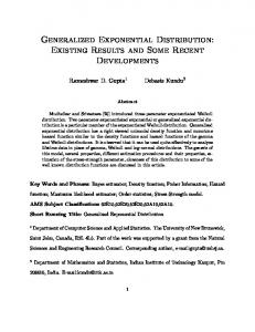
Figure 1: A clay elephant statue (left) was modeled using sketch-based implicit-surface modeling software. Then, a lapped base texture and 25 feature textures were extracted from 22 images taken with a digital camera and composited on the surface. Photography, image creation, and texture positioning was completed in under an hour.
Abstract A method is described for texturing surfaces using decals, images placed on the surface using local parameterizations. Decal parameterizations are generated with a novel O(N log N ) discrete approximation to the exponential map which requires only a single additional step in Dijkstra’s graph-distance algorithm. Decals are dynamically composited in an interface that addresses many limitations of previous work. Tools for image processing, deformation/feature-matching, and vector graphics are implemented using direct surface interaction. Exponential map decals can contain holes and can also be combined with conformal parameterization to reduce distortion. The exponential map approximation can be computed on any point set, including meshes and sampled implicit surfaces, and is relatively stable under resampling. The decals stick to the surface as it is interactively deformed, allowing the texture to be preserved even if the surface changes topology. These properties make exponential map decals a suitable approach for texturing animated implicit surfaces. CR Categories: I.3.7 [Computer Graphics]: Three-Dimensional Graphics and Realism—Color, shading, shadowing, and texture; I.3.6 [Computer Graphics]: Methodology and Techniques— Interaction Techniques; Keywords: texture mapping, decals, exponential map parameterization
1
Introduction
Texture mapping [Blinn and Newell 1976] is one of the major stages in the modeling and animation pipeline. Texture design is generally a manual process and consumes a significant amount of the effort ∗ e-mail: † e-mail:
{rms | blob}@cpsc.ucalgary.ca
[email protected]
in most animation projects. Constrained parameterization [L´evy 2001] can provide some relief if suitable images are available, however constraint placement is tedious and may need to be repeated if the surface or texture is modified. Painting tools, particularly 3D painting systems [Hanrahan and Haeberli 1990], are the real workhorses of interactive texture design. Unfortunately these tools are relatively inflexible. Useful operations such as copy-and-paste are unavailable and there is no provision for re-using existing textures. A third style of texturing interface, which combines aspects of both painting and constraint tools, is the decaling interface, introduced by Pedersen [1996]. In this approach the metaphor is that of decals, or “stickers”, which are 2D images affixed to the surface. Decals are treated as independent scene elements which are simply constrained to lie on surfaces, but may otherwise be interactively manipulated. Because a simple mapping exists between the image and the surface, 2D image processing tools can be trivially implemented. Decals are composited in real-time, mimicking 2D image compositing [Porter and Duff 1984] and vector graphics interfaces. This approach allows artists to interact with surface texture directly, using familiar 2D methods and tools. One of the largest benefits of decaling is that it allows for easy re-use of 2D images in texture design. When combined with a digital camera or image database, realistic textures can be created very quickly (Figure 1). Pedersen’s [1996] pioneering work on decaling interfaces had many practical limitations. A global base parameterization was required, complicating use on implicit and point-set surfaces and preventing animation. Decals were limited to deformed rectangles by the iterative mass-spring mesh optimization approach taken to parameterization. The user was required to manually define the decal corners, and it was not possible to automatically create a decal around an arbitrary surface curve or update the decals if the underlying surface changed. Some recent systems have taken decal-like approaches, including lapped textures [Praun et al. 2000] and texture sprites [Lefebvre et al. 2005], however neither provides support for interactive editing tools such as cut-and-paste. We present a decaling interface that addresses many of the problems encountered in Pedersen’s work [1996]. First, our approach is entirely local - we do not require a base parameterization or any other pre-processing of the surface beyond initial sampling. Our decals are based on a local exponential map parameterization (Section 4) which is generated from a single point and geodesic radius, simplifying the user interface and supporting automatic creation of decals. To efficiently generate these parameterizations we introduce a novel discrete approximation to the exponential map which requires only
a simple addition to Dijkstra’s algorithm (Section 4.2). The approximation is computed on a point set, implying that any surface which can be sampled - triangle mesh, point set, or implicit surface - can be textured with exponential map decals. Our decals compare favorably to decals created using local conformal parameterization, in particular we find that exponential map decals often preserve an intuitive sense of “squareness” that is lost with parameterizations based on global optimization. We introduce techniques for interacting with decals, including a deformation tool and surface vector graphics (Section 6). Distortion is reduced by allowing decals to have holes (Section 5.2). We also address texturing animated implicit surfaces (Section 7), a problem which has eluded previous decaling systems. We show that our approach can preserve texturing even in the presence of topological changes.
2
Related Work
Interactive painting tools [Hanrahan and Haeberli 1990] have dominated texture design interfaces. The recent development of Octree textures [Benson and Davis 2002; DeBry et al. 2002] supports 3D painting on un-parameterized surfaces. One drawback of painting interfaces is that creating realistic textures requires manual dexterity and artistic skills which most people lack. Another type of texture mapping interface is constrained parameterization [L´evy 2001; Kraevoy et al. 2003]. Here a set of constraints are manually specified between the desired texture image and the surface. Global optimization algorithms are then applied to map the image onto the surface such that the constraints are satisfied and some distortion metric is minimized. Recent advances support point sets [Zwicker et al. 2002], and atlas generation from multiple images [Zhou et al. 2005]. These systems do not address the general problem of texture design, the desired 2D image(s) are assumed to already exist. Constrained parameterization can also be used to apply decals, however the fluid interface of [Pedersen 1996] is difficult to implement because of the problem of simultaneously moving all of the constraints across the surface. Procedural texturing [Ebert 2002] provides a semi-automated approach to texture generation in exchange for detailed artistic control. Lapped textures [Praun et al. 2000; Dischler et al. 2002] take a decal-like approach to texture synthesis by overlapping many small images on a mesh. Our decals can be used to apply lapped textures to any sampled surface. Pedersen [1996] describes an interactive texture design tool which supports high-level operations such as copy-and-paste, where the copy region can be interactively dragged across the surface. Any type of surface can be used, although implicit surfaces require a time-consuming manual segmentation [Pedersen 1995]. Decals (called patchinos in this work) are created by manually connecting four points on the surface with geodesics, limiting the copy and paste regions to deformed rectangles. A rectangular or cylindrical decal shape is required by the iterative mass-spring optimization technique used to move decals. This method is noted to be unstable [Pedersen 1996], and when the mass-spring mesh collapses the decal is lost and the user must re-start the process. One of the main contributions of our work is to introduce a more robust method for representing and interacting with decals. [Lefebvre et al. 2005] describe an interactive decaling system based on hardware-accelerated octree textures. Basic interactive positioning and blending composition is supported. Like 3D painting, decals are applied using planar projection, which does not easily support more complex editing operations. Planar projection is in some
sense a parameterization, however cut-and-paste requires two projections, introducing significant distortion on curved surfaces. Similarly, Autodesk ImageStudio [Autodesk 2005] supports application of decals using planar projection, as well as conformal decals which exhibit the same issues as described in Section 5.1. One approach to decaling is to simply drag images around in texture space, where a single-chart surface parameterization has already been computed. Automatic algorithms exist for meshes [Floater 1997; L´evy et al. 2002; Desbrun et al. 2002; Sheffer et al. 2005; Gu and Yau 2003] and point sets [Floater and Reimers 2001; Zwicker et al. 2002; Alexa et al. 2003]. Any single-chart parameterization for a complex surface necessarily introduces significant distortion, resulting in decals that change size as they are dragged across the surface. When applied locally in the region of a decal, the global distortion minimizations used by these methods can result in unexpected deformation (Section 5.1). Similar problems occur with chart atlases [Maillot et al. 1993; Sorkine et al. 2002; Grimm 2004; Zhang et al. 2005], undesirable deformations can also be produced by distortion discontinuities at atlas boundaries. Parameterizing implicit surfaces presents some additional challenges, particularly if the surface is animated. Existing approaches are not interactive and provide either limited control over texture application [Tigges and Wyvill 1999] or require topological knowledge a priori [Grimm 2004]. Octree texturing has limited applicability because there is no way to map an implicit surface back to the “rest pose” described by [Lefebvre et al. 2005] during animation. None of these methods address the issue of animated topology change. Our system produces consistent and predictable results in these situations. Additional control is available to the animator since decals can be keyframed.
3
Overview
The goal of our decaling interface is to make 3D surface texture design as fluid and straightforward as 2D vector graphics and image compositing is with software such as Adobe Illustrator. This is accomplished by hiding all aspects of surface parameterization in the texturing interface. Unlike [Pedersen 1996], we do not require a global base parameterization. Each decal is an independent object in the system, with a simple layer order to determine the decal compositing sequence. The artist interacts with decals, rather than the underlying parameterizations. All decals are dynamically composited each frame using the alpha blending and texturing mapping hardware found on commodity graphics hardware (Figure 2a). Other blending modes, such as dodge and burn, can be implemented with programmable GPUs. Decals are dynamically generated based on a center point, orientation, and radius. A decal is dragged across the surface by repositioning the center point with ray-surface intersections. The orientation and radius are interactively controlled with simple 3D widgets (Figure 2b). Decals can also be used as canvases for 2D operations. 2D vector graphics objects such as lines and curves can be manipulated by moving control points on the surface (Figure 2d). Local featurealignment can be performed interactively by manipulating 2D image deformations, again via 3D control points (Figure 2c). Curves drawn in screen space can also be projected into decals and used to control image processing operations such as blurring (Figure 2a) and composited copy-and-paste (Figure 2b). Painting tools can be implemented by using decals as local canvases for traditional 2D or 3D painting interfaces. The advantage of the decal-as-canvas metaphor is that decals can be (re)moved.
Figure 2: Three overlapping semitransparent decals are composited in (a, top). A selection region is used to blur the blue decal (a, bottom) while leaving the red and green decals unchanged. In (b), the two decals inside the selection region are baked into a new decal which has been pasted back onto the surface several times. In (c), a lattice tool is used to deform the decal. A surface vector line with an endcap is created between the control points in (d,top) by rendering a 2D line into an automatically-generated decal. Surface curves can be rendered using a set of vector lines (d,bottom). The underlying decals are shown as checkerboards. In (e), the decals on two separate implicit surfaces are automatically updated when the surfaces are blended.
Finally, decals maintain consistency as the underlying surface changes. Difficult cases, such as topological change in implicit surfaces (Figure 2e), are handled robustly. Decals also provide a mechanism for texturing animated implicit surfaces. In the following sections we will explain how our decals are created, as well as describe the implementation and use of our decaling interface.
4
Exponential Maps
Our goal is to map a 2D image onto a 3D surface S such that the center of the image lies at some point p on S. The exponential map [do Carmo 1976] is one method of defining such a mapping, essentially creating a 2D coordinate system on the surface around p. The exponential map expp takes points on S to the tangent plane Tp at p. This is accomplished via geodesics. For any unit vector v ∈ Tp , there exists a geodesic gv parameterized by arc length such that gv (0) = p and gv0 (0) = v. Essentially, gv are the geodesics that splay out radially from p (Figure 3). For any point q in the neighbourhood of p, a unique radial
geodesic gv passes through it. Hence, q can be mapped to Tp with the polar coordinates (rg , θg ), where rg is the geodesic distance from p to q and θg is the polar angle of v in Tp . These are the geodesic polar coordinates [do Carmo 1976]. Geodesic polar coordinates can alternatively be expressed as normal coordinates (u, v) in any orthogonal basis {e1 , e2 } of the tangent plane. Normal coordinates are by definition a mapping from the plane to the surface and hence would seem to be an ideal solution for texture mapping. The inverse function theorem ensures that for any differentiable point on a surface, expp is defined and differentiable in some neighbourhood around p [do Carmo 1976]. If S is restricted to smooth manifolds, then the Hopf-Rinow theorem [Cheeger and Ebin 1975] states that expp is guaranteed to be defined on the entire surface. However, the map is still only diffeomorphic on a local neighbourhood of p, implying that foldovers in the parameterization will occur if the neighbourhood grows too large. An example of a sphere texture-mapped using an analytic exponential map parameterization is shown in Figure 4. In the neighbourhood of p (at the center of the leftmost image), the checkerboard exhibits low distortion. The parameterization is neither conformal nor area-preserving, as can be observed on the back of the sphere. However, the parameterization on the front of the sphere is very “square” and hence is ideal for applying a decal.
4.1
Previous Approaches to Exponential Maps
Projection of the neighbour vertices of a triangle mesh vertex p onto the tangent plane at p is a commonly-used local approximation to expp . Welch and Witkin [1994] describe a more robust technique for approximating expp on the 1-ring of a triangle mesh vertex. This method has seen wide use as a component of global parameterization algorithms [Floater 1997], however the approximation does not extend beyond the 1-ring. Figure 3: The exponential map at a point p takes geodesic curves originating at p in (a) to straight vectors emanating from the origin of the tangent plane Tp in (b). Geodesic “circles”, defined as isocontours of the geodesic distance function, are mapped to circles about the origin of Tp .
The key difficulty in computing expp is in finding the radial geodesic gv that passes through a surface point q. Dijkstra’s algorithm [Dijkstra 1959] is perhaps the best-known technique for approximating geodesic distances. However the piecewise linear geodesics produced by Dijkstra’s algorithm always lie on graph edges
rotate Tr around any vector perpendicular to both nr and np by angle acos(nr · np ). This transformed plane is co-planar with Tp and has a new basis (x0r , y0r , np ). Now rotate around the normal np by angle acos(x0r · xp ) to align the in-plane basis vectors. The second rotation can be treated as a 2D rotation in the tangent plane and applied directly to ur,q (Figure 5b), so if the rotation angle is θp,r , then up,q can be approximated by
and hence provide a very poor estimation of θg .
ˆp,q = up,r + Rot2D(θp,r ) · ur,q u
(2)
as shown in Figure 5c (the red vector is Rot2D(θp,r ) · ur,q ). Note that the in-plane basis vectors xr and yr are completely arbitrary, the only requirement is that they be perpendicular.
Figure 4: Checkerboard texture applied to sphere using analytic parameterization (top) and discrete approximation (bottom). Front views show very high correspondence. Overall patterns in side and back views are similar, however the approximation exhibits errors accumulated during propagation. Rightmost images show 2D parameter space for lower-resolution triangulated spheres. A number of algorithms that produce more accurate geodesic distance approximations are available. See [Mitchell 2000] for a recent survey. The fast-marching mesh geodesic distance method presented by [Kimmel and Sethian 1998] runs in O(N log N ) time. [Surazhsky et al. 2005] describe an algorithm which computes approximate mesh geodesic distances in a fraction of the time taken for the fast-marching approach. These algorithms are heavily dependent on the underlying mesh structure and hence unlikely to be adaptable to unstructured geometry such as point clouds. Although not explicitly used for local parameterization, the geodesic fans computed by [Zelinka and Garland 2004] are essentially coarse approximations of radial geodesics, and hence also approximate the exponential map on meshes. Mesh vertices could be parameterized by projecting them onto a geodesic fan, however this is computationally intensive and may result in local foldovers.
4.2
Discrete Exponential Map Approximation
In the discrete setting, we have a set of points on some surface S. To approximate the exponential map at p, we must find the geodesic distance and polar angle for each other point q on the surface. We approach the problem by computing these values directly in the tangent plane at p, rather than trying to find the surface geodesics. The resulting algorithm requires only a simple vector addition of the piecewise-linear geodesics produced by Dijkstra’s algorithm. First, consider the base case, with 3 points p, r, and q. The geodesics from p to r and r to q are known, however the geodesic from p to q is not (Figure 5a). Our goal is not to find this geodesic but rather to compute up,q = expp (q), the 2D point in normal coordinates of Tp . Linearity allows us to rewrite up,q as up,q = v + (up,q − v), where v is any other 2D point. Let v = expp (r) = up,r . This is the known geodesic from p to r. We now have up,q = up,r + (up,q − up,r )
(1)
where (up,q − up,r ) is unknown. This 2D vector corresponds to some curve on the surface from r to q, although it is not in general a geodesic. We approximate this curve with the known geodesic from r to q. In the tangent plane at r, let ur,q = expr (q). This is the necessary vector, however it is defined in normal coordinates of Tr with respect to some 3D basis (xr , yr , nr ) and we need it in the 3D basis (xp , yp , np ) of Tp . To transform between the bases,
We have made two approximations. First, assuming (up,q − up,r ) is a geodesic is only correct on developable surfaces, where the Gaussian curvature K = 0. Second, we used a simple affine transformation to map between the tangent planes at r and p. Minding’s theorem states that this map is isometric only between surfaces where K is a constant [do Carmo 1976]. Otherwise, some additional error is introduced. We have also assumed that the exponential map at any p can be computed in a small neighbourhood around p. In the discrete setting this local exponential map is approximated by transforming linear segments into the tangent plane. This local approximation, which we will denote exp c p (q) = b up,q , is described in more detail in Section 4.3.
Figure 5: The normal coordinates up,q of the unknown radial geodesic from p to q in (a) can be approximated using the known geodesics from p to r and r to q. The vector to ur,q (in normal coordinates at r) is transferred to the tangent plane at p using a 2D rotation with angle θp,r , producing the red vector in (b). This vector is an approximation to (up,q − up,r ) and can be added to up,r ˆp,q . (c) to get the approximate result u The final algorithm for approximating the exponential map can now be described. First, Dijkstra’s algorithm is run from point p to generate, for each other surface point q, a piecewise-linear curve from p to q with vertices {pi }. These linear segments are then sequentially “lifted” into Tp by evaluating ˆp,q = b u up0 ,p1 +
X i≥1
upi ,pi+1 Rot2D (θp,pi ) · b
(3)
which amounts to summing the 2D vectors produced by transforming each successive linear 3D segment into Tp . Note that b upi ,pi+1 is mapped directly into the tangent plane at p, rather than incrementally mapping to each previous tangent plane. The conditions described above on the tangent plane mapping hold regardless of the distance between p and pi . Transforming the vector through each previous tangent plane results in much higher total error. Equation 3 approximates the exponential map by transforming 3D points into the 2D tangent plane at p. The magnitude of the resulting 2D vector approximates the geodesic distance with more accuracy than the value produced by Dijkstra’s algorithm. The improvement comes from the use of vector addition, rather than the
scalar addition used by Dijkstra’s algorithm. This result is reminiscent of the improvement in Euclidean distance approximation observed when using vector distance transforms instead of chamfer distance transforms [Satherley and Jones 2001].
4.3
Implementation Details and Properties
The sampling rate of the underlying point set largely determines the accuracy in the discrete exponential map. The first restriction on sampling rate is that local geodesic neighbourhoods must be computable. We use a k nearest geodesic neighbour scheme, with k = 15. If mesh connectivity is unavailable, nearest Euclidean neighbours are assumed to be geodesic neighbours. This assumption is valid only if global sampling criteria hold [Dey and Goswami 2004]. In some cases, such as subdivision and implicit surfaces, additional samples can be generated automatically to resolve undersampling. Otherwise, algorithms that take a global approach to the neighbour-finding problem are necessary [Fleishman et al. 2005]. Related to the problem of computing geodesic neighbourhoods is that of computing the local discrete exponential map, exp c p . We assume that the length |p − q| is a good estimate of geodesic distance and determine the normal coordinates by finding the angle θq be→ and Tp , and then rotating − → by θq around the tween the vector − pq pq → × np . The rotation must always be in the direction of the axis − pq normal, hence if np · nq < 0 the rotation angle is π − θq . Given adequate sampling, we have found the discrete exponential map to be very robust in practice. In particular, there is no requirement that the surface sampling be regular. Our interactive system is based on implicit surfaces visualized using marching cubes. A quick surface sampling can be created based on the vertices output by marching cubes. Since our marching cubes implementation does not generate mesh connectivity data, Euclidean neighbours are used to create the k-NN lists. Marching cubes is known to produce very irregular vertex distributions, resulting in a worst-case sampling density much lower than the equivalent number of points evenly distributed. The resulting parameterization is visually indistinguishable from that computed with a more regular sample distribution, even at moderate tessellation resolutions (Figure 6). The algorithm does assume that accurate surface normals are available. Noisy normals introduce local distortion but the algorithm remains stable. Noise in the point set affects geodesic distances and causes the parameterization to quickly degenerate. The discrete exponential map we describe is very efficient. Us-
ing a priority queue, the running time of Dijkstra’s algorithm is O(N log N ) in the number of surface samples. The discrete exponential map can be incrementally computed in-line with the Dijkstra propagation, hence the running time remains O(N log N ). Dijkstra’s algorithm is known to be non-convergent. While we have not found any theoretical proof, we have some evidence that the discrete exponential map does converge. In numerical tests on a ˆp,q (Equation 2) converges quadratically to the analytic sphere, u value of up,q as the distances between p, r and r, q go to zero. For longer piecewise-linear geodesic paths the numerical convergence is only linear, likely due to the accumulation of error at each approximation step. In general, the discrete exponential map appears to visually converge as the sampling rate is increased. One property of exponential map parameterization is that fully developable surfaces (surfaces with zero Gaussian curvature everywhere) are parameterized with no distortion. Our discrete approximation reproduces this property, as seen in Figure 7.
Figure 7: Parameterizations generated for developable surface patches - (a) swiss roll, (b)/(c) cone front/back, and (d) box. Artifacts occur on the cone because it is not developable at the apex.
5
Decal Parameterizations
Our interactive texturing system is based on local exponential map parameterizations which we call ExpMap decals. An ExpMap decal is defined by a seed point p on the surface and a geodesic radius r. The decal is generated by first running Dijkstra’s algorithm to find an approximate geodesic disc with radius r + δ. The δ value is necessary to ensure that the disc of radius r is contained within the decal, since the particular discretization may otherwise result in clipping We use the largest neighbour distance as δ, avoiding problems with decals that are small relative to the sampling rate. This approximate geodesic disc is then parameterized using the algorithm described in Section 4.2. Finally the parameterization is √ scaled by 1/ 2r and translated by (0.5, 0.5), so that the “geodesic square” inscribed in the disc lies at [0, 1] × [0, 1] in parameter space. Decals can be interactively rendered using texture-mapped triangles or point splats. We store decals as local parameterizations of portions of the marching cubes mesh, similar to [Praun et al. 2000]. Compositing is performed dynamically using alpha-blending. This may involve storage and rendering of hundreds of decal parameterizations, which is acceptable for interactive editing but less so if many decaled objects are part of a complex scene. For this case the decals can be baked into a global parameterization or octree texture.
5.1 Figure 6: The sampling rate has little effect on this decal. Figures (a)/(b) and (c)/(d) have the same number of surface point samples. ExpMap robustly handles the irregular sampling in (a) and (c). Mesh edges are shown here to convey the sample distribution; the parameterization is computed directly from the vertices.
Comparison to Mesh Parameterization Methods
We have compared our ExpMap decals with those generated using a variety of automatic mesh parameterization techniques. The same decal creation procedure is used - we segment an approximate geodesic disc from the mesh, and then parameterize this disc.
We first compared our results with several mesh parameterization algorithms that require a boundary. It is relatively simple to map the approximate geodesic disc to a circular boundary. We tried the shape-preserving weights [Floater 1997], geodesic weights [Lee et al. 2005], and area-preserving intrinsic weights [Desbrun et al. 2002]. In all of these cases we observed significantly higher distortion, likely introduced by the boundary mapping. In addition, the distortion is not frame-coherent, so while the user drags the decal across the surface it randomly changes size and orientation. Stretch-minimization [Sander et al. 2001] had less distortion but similar problems with orientation, and was highly non-interactive. Better results were found using free-boundary conformal maps [Desbrun et al. 2002], with vertices near the seed point constrained to minimize (but not completely prevent) undesired decal rotation. We have observed that these decals are identical to ExpMap decals only on developable surfaces. On a sphere the “edges” of the square are similar, but the internal distortion is different (conformal decals are less uniform). However, in many relatively simple cases the square edges are not as well-preserved (Figure 8). Because ExpMap decals are based on geodesics, they distort only when the geodesics distort. Global conformal optimization spreads out the distortion, producing decals with edges that we feel are much less “square” than ExpMap decals.
Figure 9: Comparison between ExpMap (a), Hybrid (b), and Conformal (c) decals. The Hybrid decal has less distortion but maintains a geodesic radius.
patchino optimization procedure required a complete mass-spring mesh, however it is trivial to implement with ExpMap decals. To create partial decals, the unwanted points are removed from the Dijkstra computation and left unparameterized. In our system we simply halt the Dijkstra propagation at points whose absolute Gaussian curvature is larger than a user-defined threshold (Figure 10b). Other alternatives could include halting at creases, or based on boundaries painted by a user. Partial decals illustrate an interesting property of our discrete exponential map. Surface geodesics (such as those described by [Surazhsky et al. 2005]) would pass around the “hole” and collide behind it, creating a texture discontinuity. Because we perform the incremental vector addition in the 2D tangent space, the “geodesic curves” on the surface actually pass through the feature - as if it were replaced by a smooth surface. Note, however, that because the path taken from the seed point to the points behind the hole is less direct, the approximation error is larger.
Figure 8: Comparison between conformal (a,c) and ExpMap (b,d) decals. In these cases the global conformal optimization results in decals which are less “square” than the ExpMap decals. In (c), the conformal parameterization is clipped because it extends beyond the boundary of the decal (near the blue star). The problem is magnified during interaction. For example, on the cylinder in Figure 8b, the conformal decal begins to distort before the edge of the texture crosses the edge of the cylinder. This behavior is very unintuitive. Another problem is that the conformal parameterization is not necessarily contained within the geodesic disc. This can result in the decal being clipped (Figure 8c). Conformal decals do have some desirable properties, particularly with respect to distortion. In areas of high distortion, the “greedy” nature of the discrete exponential map can produce artifacts and even local foldovers. Generally this occurs with decals that cover undersampled regions of the surface with significantly varying curvature. These artifacts can be repaired by applying conformal parameterization as a post-process. Highly-distorted regions in the ExpMap decal are discarded and re-parameterized using natural conformal parameterization, with the remaining ExpMap parameter values used as constraints [Desbrun et al. 2002]. The result is a combined ExpMap / Conformal decal, or Hybrid decal (Figure 9).
5.2
Partial Decals
Like patchinos [Pedersen 1996], ExpMap decals become highly distorted when passing over large protrusions on an otherwise relatively flat surface (Figure 10a). Pedersen noted that this situation could be avoided if the patchino contained a hole which passed around the feature. His system could not support this because the
Figure 10: In the case of a relatively smooth surface with a highfrequency feature, the decal is significantly distorted (a). By halting the vector propagation based on curvature magnitude, a hole is created as the decal passes around the feature (b). The distortion behind the feature is also avoided (insets).
6
Interactive Techniques
The user manipulates decals in our interface with a simple 3D control (Figure 2b,top). The decal is moved by dragging the center point across the surface, rotated with the circle, and scaled with the outer point. The parameterization is automatically recomputed as needed. To fit a decal around a set of points {pi } projected onto the surface from a screen-space curve, we project the center of the 2D bounding box to find a seed point, and then run the ExpMap propagation until all pi have been reached. To implement user-interface tools, it is useful to be able to map between the 3D surface and 2D parameter space for points not in the initial point set. A 2D parameter u can be mapped to 3D q using barycentric interpolation in the 2D triangle containing u (a
Delauney triangulation must first be computed for point sets). Mapping from 3D q to 2D u would ideally be done by adding q to the point set and recomputing the parameterization, however this can be expensive. A quick approximation is to propagate the parameterization from the nearest neighbour to q using Equation 2.
vertices of screen-space curves onto the surface and then connecting them with line elements (Figure 12). One advantage of this approach is that portions of the surface which are occluded can still be painted, unlike the projective texturing found in 3D painting tools.
Our decaling interface is highly interactive. Decal update times scale roughly linearly with the number of point samples, and are independent of other decals. On a 1.6 Ghz laptop, the ExpMap parameterizations in Figures 6a and 6c are computed at 121 and 362 fps (6c has 4.4 times as many points). User interface overhead reduces visual update times to 78 and 31 fps, respectively.
6.1
Decal Deformation
It is often useful to be able to deform a decal, either to match image features to surface features, or to correct for some unwanted distortion. Image deformations can be applied to the texture, however this approach is non-interactive for high-resolution images and limits texture re-use. Instead, we deform the decal parameterization. If the image deformation ω is desired, then the inverse deformation ω −1 must be applied to the parameterization. Since deformations based on the point samples may exhibit frame-incoherence, a functional space deformation is used. To avoid introducing foldovers, we construct a deformation with infinite support. Our deformation tool is based on C 2 variational scattered-data interpolation, also known as thin-plate splines or radial basis functions. A set of point constraints between sources (u, v) and destinations (u0 , v 0 ) is created by projecting the 3D handles into 2D. Two standard 2D thin-plate splines are fitted [Turk and O’Brien 1999], wu which maps (u0 , v 0 ) to the corresponding u values, and wv which maps to the v values. The warp function w = (wu , wv ) is then evaluated for each point in the parameterization. Since the variational solution is based on point constraints, both lattice deformation (Figure 2) and feature alignment (Figure 11) is possible.
Figure 11: Decal deformation. In (a), the decal image is too small to cover the eyeball. Using the lattice deformation shown in Figure 2 results in a stretched pupil (b). Placing extra constraint points around the pupil (c) produces the desired result (d).
6.2
Surface Vector Graphics
Decals can be used as canvases for 2D vector graphics. A geodesic line element can be created between two points by generating a decal originating at one point with a radius equal to the geodesic distance to the second point. If the decal is relatively un-distorted, uniform line width can be maintained by scaling linearly based on the decal radius. Lines across regions of widely varying curvature can be subdivided into multiple decals to reduce distortion. Geodesic line elements can be used as a building block for other surface vector elements. We create surface curves by projecting the
Figure 12: In (a), a vertebra model is extracted from a volume dataset and annotated. Though the surface is quite rough, there is little distortion in the text. In (b), the vertices of a screen-space stroke (top) are projected onto the surface and connected with vector lines. The stroke is continuous across occluded areas (bottom).
7
Surface Deformation and Animation
Most texture-mapping schemes assume that the underlying surface is static. Significant surface deformation or topology change requires re-parameterization. In general, it is very difficult to transfer texture between parameterizations in a coherent manner. Even simple remeshing can be problematic. Decals are stable under remeshing (Figure 6) and easily handle deformation and topology change. The seed points are simply moved to the new surface, and the decal parameterizations regenerated. ExpMap decals will flow onto the new surface in a consistent and predictable manner (Figure 13b). Because decals preserve texture across remeshing and surface deformation, they are an alternative for texturing animated implicit surfaces. Our modeling system is based on hierarchical implicit surfaces [Wyvill et al. 1999], where the surface is a composition of simpler shapes. After texturing is complete, each decal is associated with the nearest shape and stored at local coordinates in the shape’s reference frame. The decal position for any frame can be found by performing a gradient walk from these local coordinates to the surface. In practice, frame-coherence is largely determined by the amount of distortion in the decal. With high distortion the parameterization is likely to “pop” from frame to frame in the distorted regions. The popping occurs because the sampling rate is too low in the distorted regions, so denser and more regular sampling can help to some extent. Another option is to compute a mesh and use a more robust but slower geodesic computation [Surazhsky et al. 2005].
8
Results
Combined with a digital camera, our decaling system provides a quick and easy-to-use interface for texturing 3D models. Using an existing model and a few snapshots, the dog in Figure 13 was composited in a few minutes. The base fur texture was generated
by uniformly distributing fur decals across the surface, essentially creating a lapped texture [Praun et al. 2000].
painters, the ability to easily mix-and-match from existing images makes decaling a useful addition to the texture design toolbox.
An example of modeling a real-world object is shown in Figure 1. A rough 3D model was generated using sketch-based modeling software, and then 22 snapshots of the clay statue were taken. A base texture was generated using the lapping technique, and then relevant features were cut out of each image and attached to the model. The entire process, from clay statue to textured 3D model, took several hours, with the most time-consuming step being the manual color-balancing necessary to compensate for the poor color reproduction of the digital camera.
We anticipate a wide range of applications for ExpMap decal parameterizations in interactive tools. Decaling interfaces for bump and displacement mapping are obvious extensions. Decals can also be used for interactive surface re-sampling and repair. Decals may be useful in discrete geometry modeling contexts for implementing tools such as surface deformation and geometry cut-and-paste. We are also exploring application of decal parameterization to highquality tessellation of implicit surfaces.
The textures for the implicit gremlin model (Figure 14) were taken from a variety of sources, including photographs of a frog, a painting, and the author. The images were segmented and re-colored using image-processing software, and then pasted onto the suface. Many of the textures are re-used multiple times. For example, each finger and toe uses the same set of decals, although they are deformed to better fit the particular geometry.
Figure 13: In (a), an irregular piece of fur texture is automatically lapped to create a base fur texture on a model of a dogs head. The eyes, a nose, and a few additional pieces of fur were cut from other photographs. Placing them on the surface takes only a few minutes. In (b), the existing texture is automatically preserved when the ears are modified and horns added. No manual adjustments of the decals were performed.
9
Conclusions and Future Work
We have described an interactive texture mapping interface based on decals generated using a new discrete exponential map approximation. A key benefit is that sampled surfaces can be textured without a global base parameterization. Surfaces created in our implicit modeling system can be immediately textured. Furthermore, if the designer finds that the surface must be modified, extensive changes can be made without losing the textures applied so far. ExpMap decals enable new texturing tools, such as surface vectorgraphics, selection of curved regions, and decals with holes, which were not possible using existing methods [Pedersen 1996]. In our experience, ExpMap decals generally provide predictable and consistent results, and address difficult problems such as animating implicit surfaces and topology change. Our interface gives designers high-level tools to composite and manipulate decals, hiding all aspects of the underlying parameterization. This is a fluid and efficient way to texture surfaces, particularly for those who are not skilled at texture painting. Even for texture
Figure 14: The decal texture for this implicit gremlin model was created using 19 different images cut out of various photographs and then manipulated using 2D image editing software. The texture consists of 392 decals, although only 78 were placed manually. The 6 images used to texture the hand are shown.
10
Acknowledgements
The authors wish to thank the anonymous reviewers, Alla Sheffer, Michael Garland, Brendan Lane, Tim Gatzke, Dan Julius, Ailidh Carpendale, and Shadow the dog. This work was funded by NSERC and iCore.
References A LEXA , M., K LUG , T., AND S TOLL , C. 2003. Direction fields over point-sampled geometry. In Proceedings of WSCG 03. AUTODESK, 2005. Imagestudio. www.autodesk.com/imagestudio. B ENSON , D., AND DAVIS , J. 2002. Octree textures. ACM Trans. Graph. 21, 3, 785–790. B LINN , J., AND N EWELL , M. 1976. Texture and reflection in computer generated images. Communications of the ACM 19, 10, 542–547. C HEEGER , J., AND E BIN , D. G. 1975. Comparison Theorems in Riemannian Geometry. North-Holland Mathematical Library.
D E B RY, D., G IBBS , J., P ETTY, D. D., AND ROBINS , N. 2002. Painting and rendering textures on unparameterized models. ACM Trans. Graph. 21, 3, 763–768.
M ITCHELL , J. 2000. Geometric Shortest paths and network optimization. Elsevier Science, ch. Handbook of Computational Geometry, 633–702.
D ESBRUN , M., M EYER , M., AND A LLIEZ , P. 2002. Intrinsic parameterizations of surface meshes. Comp. Graph. Forum 21, 3, 383–392.
P EDERSEN , H. K. 1995. Decorating implicit surfaces. In Proceedings of SIGGRAPH 95, 291–300.
D EY, T. K., AND G OSWAMI , S. 2004. Provable surface reconstruction from noisy samples. In Proceedings of the 20th annual symposium on Computational geometry, 330–339. D IJKSTRA , E. 1959. A note on two problems in connexion with graphs. Numerische Mathematik 1, 269–271. D ISCHLER , J.-M., M ITAUD , K., L E´ VY, B., AND G HAZANFAR POUR , D. 2002. Texture particles. Comp. Graph. Forum 21, 3.
P EDERSEN , H. K. 1996. A framework for interactive texturing operations on curved surfaces. In Proceedings of SIGGRAPH 96, 295–302. P ORTER , T., AND D UFF , T. 1984. Compositing digital images. In Proceedings of SIGGRAPH 84, vol. 18, 253–259. P RAUN , E., F INKELSTEIN , A., AND H OPPE , H. 2000. Lapped textures. In Proceedings of ACM SIGGRAPH 2000, 465–470.
DO
S ANDER , P., S NYDER , J., G ORTLER , S., AND H OPPE , H. 2001. Texture mapping progressive meshes. In Proceedings of ACM SIGGRAPH 2001, 409–416.
E BERT, D. S., Ed. 2002. Texturing and Modeling: A Procedural Approach. Morgan Kaufmann. ISBN 1558608486.
S ATHERLEY, R., AND J ONES , M. 2001. Vector-city vector distance transform. Computer Vision and Image Understanding 82, 3, 238–254.
F LEISHMAN , S., C OHEN -O R , D., AND S ILVA , C. T. 2005. Robust moving least-squares fitting with sharp features. ACM Trans. Graph. 24, 3, 544–552.
S HEFFER , A., L E´ VY, B., M OGILNITSKY, M., AND B O GOMYAKOV, A. 2005. Abf++: fast and robust angle based flattening. ACM Trans. Graph. 24, 2, 311–330.
C ARMO , M. P. 1976. Differential Geometry of Curves and Surfaces. Prentice Hall.
F LOATER , M., AND R EIMERS , M. 2001. Meshless parameterization and surface reconstruction. Comp. Aided Geom. Design 18, 77–92. F LOATER , M. 1997. Parametrization and smooth approximation of surface triangulations. Comp. Aided Geom Design 14, 231–250. G RIMM , C. 2004. Parameterization using manifolds. International Journal of Shape Modeling 10, 1, 51–80. G U , X., AND YAU , S.-T. 2003. Global conformal surface parameterization. In Proceedings of the Eurographics/ACM SIGGRAPH symposium on Geometry processing, 127–137. H ANRAHAN , P., AND H AEBERLI , P. E. 1990. Direct wysiwyg painting and texturing on 3d shapes. In Proceedings of SIGGRAPH 90, vol. 24, 215–223. K IMMEL , R., AND S ETHIAN , J. 1998. Computing geodesic paths on manifolds. Proc. of National Academy of Sci. 95, 15 (July), 8431–8435. K RAEVOY, V., S HEFFER , A., AND G OTSMAN , C. 2003. Matchmaker: Constructing constrained texture maps. ACM Trans. Graph. 22, 3, 326–333.
S ORKINE , O., C OHEN -O R , D., G OLDENTHAL , R., AND L ISCHINSKI , D. 2002. Bounded-distortion piecewise mesh parameterization. In Proceedings of IEEE Visualization, 355–362. S URAZHSKY, V., S URAZHSKY, T., K IRSANOV, D., G ORTLER , S. J., AND H OPPE , H. 2005. Fast exact and approximate geodesics on meshes. ACM Trans. Graph. 24, 3, 553–560. T IGGES , M., AND W YVILL , B. 1999. A field interpolated texture mapping algorithm for skeletal implicit surfaces. In Computer Graphics International, 25–32. T URK , G., AND O’B RIEN , J. F. 1999. Shape transformation using variational implicit functions. In Proceedings of ACM SIGGRAPH 99, 335–342. W ELCH , W., AND W ITKIN , A. 1994. Free-form shape design using triangulated surfaces. In Proceedings of SIGGRAPH 94, 247–256. W YVILL , B., G UY, A., AND G ALIN , E. 1999. Extending the csg tree. warping, blending and boolean operations in an implicit surface modeling system. Comp. Graph. Forum 18, 2, 149–158. Z ELINKA , S., AND G ARLAND , M. 2004. Similarity-based surface modelling using geodesic fans. In Proceedings of the Eurographics Symposium on Geometry Processing, 209–218.
L EE , H., T ONG , Y., AND D ESBRUN , M. 2005. Geodesics-based one-to-one parameterization of 3d triangle meshes. IEEE MultiMedia 12, 1, 27–33.
Z HANG , E., M ISCHAIKOW, K., AND T URK , G. 2005. Featurebased surface parameterization and texture mapping. ACM Trans. Graph. 24, 1, 1–27.
L EFEBVRE , S., H ORNUS , S., AND N EYRET, F. 2005. Texture sprites: Texture elements splatted on surfaces. In ACMSIGGRAPH Symposium on Interactive 3D Graphics (I3D).
Z HOU , K., WANG , X., T ONG , Y., D ESBRUN , M., G UO , B., AND S HUM , H.-Y. 2005. Texturemontage: Seamless texturing of arbitrary surfaces from multiple images. ACM Trans. Graph. 24, 3, 1148–1155.
L E´ VY, B., P ETITJEAN , S., R AY, N., AND M AILLOT, J. 2002. Least squares conformal maps for automatic texture atlas generation. In Proceedings of ACM SIGGRAPH 2002, 362–371. L E´ VY, B. 2001. Constrained texture mapping for polygonal meshes. In Proceedings of ACM SIGGRAPH 2001, 417–424. M AILLOT, J., YAHIA , H., AND V ERROUST, A. 1993. Interactive texture mapping. In Proceedings of SIGGRAPH 93, 27–34.
Z WICKER , M., PAULY, M., K NOLL , O., AND G ROSS , M. 2002. Pointshop 3d: An interactive system for point-based surface editing. ACM Trans. Graph. 21, 3, 322–329.


![Marketing to Millennial Moms - Exponential Interactive [PDF]](https://m.moam.info/img/260x300/marketing-to-millennial-moms-exponential-interacti_64a4de66098a9e72478b463f.jpg)