IEEE TRANSACTIONS ON SUSTAINABLE ENERGY, VOL. 3, NO. 2, APRIL 2012
295
Interactive Distributed Generation Interface for Flexible Micro-Grid Operation in Smart Distribution Systems Alireza Kahrobaeian and Yasser Abdel-Rady I. Mohamed, Senior Member, IEEE
Abstract—This paper presents an interactive distributed generation (DG) interface for flexible micro-grid operation in the smart distribution system environment. Under the smart grid environment, DG units should be included in the system operational control framework, where they can be used to enhance system reliability by providing backup generation in isolated mode, and to provide ancillary services (e.g. voltage support and reactive power control) in the grid-connected mode. To meet these requirements, the proposed flexible interface utilizes a fixed power–voltage–current cascaded control structure to minimize control function switching and is equipped with robust internal model control structure to maximize the disturbance rejection performance within the DG interface. The proposed control system facilitates flexible and robust DG operational characteristics such as 1) active/reactive power (PQ) or active power/voltage (PV) bus operation in the grid-connected mode, 2) regulated power control in autonomous micro-grid mode, 3) smooth transition between autonomous mode and PV or PQ grid connected modes and vice versa, 4) reduced voltage distortion under heavily nonlinear loading conditions, and 5) robust control performance under islanding detection delays. Evaluation results are presented to demonstrate the flexibility and effectiveness of the proposed controller. Index Terms—Distributed generation (DG), flexible control, micro-grids, smart distribution systems.
I. INTRODUCTION
F
LEXIBLE operation of distributed generation (DG) units is a major objective in future smart power grids [1]–[4]. The majority of DG units are interfaced to grid/load via power electronics converters. Current-controlled voltage-sourced inverters (VSIs) are commonly used for grid connection [5]. Under the smart grid environment, DG units should be included in the system operational control framework, where they can be used to enhance system reliability by providing backup generation in isolated mode, and to provide ancillary services (e.g. voltage support and reactive power control) in the grid-connected mode. These operational control actions are dynamic in nature as they depend on the load/generation profile, demand-side management control, and overall network optimization controllers (e.g., grid reconfiguration and
Manuscript received May 27, 2011; revised September 19, 2011; accepted November 05, 2011. Date of current version March 21, 2012. The authors are with the Department of Electrical and Computer Engineering, University of Alberta, Edmonton, T6G-2V4, Canada (e-mail:
[email protected]). Color versions of one or more of the figures in this paper are available online at http://ieeexplore.ieee.org. Digital Object Identifier 10.1109/TSTE.2011.2178045
supervisory control actions) [4]. To achieve this vision, the DG interface should offer high flexibility and robustness in meeting a wide range of control functions, such as seamless transfer between grid-connected operation and islanded mode; seamless transfer between active/reactive power (PQ) and active power/voltage (PV) modes of operation in the grid connected mode; robustness against islanding detection delays; offering minimal control-function switching during mode transition; and maintaining a hierarchical control structure. Several control system improvements have been made to the hierarchical control structure to enhance the control performance of DG units either in grid-connected or isolated micro-grid systems [5]–[11]. However, subsequent to an islanding event, changing the controlling strategy from current to voltage control, in a hierarchical control framework, may result in serious voltage deviations especially when the islanding detection is delayed [12]. Further, mode transition transients will be imposed on the output voltage vector, where both the magnitude of the output voltage and the power angle will be subjected to disturbances. Few studies addressed the extended nature of micro-grid operation during mode transition and flexible operation. Seamless voltage transfer control between grid-connected and isolated local-voltage-controlled modes is reported in [13]. An indirect current control technique is proposed in [12] to mitigate voltage transients in mode transition. In [14], a direct control structure that mimics synchronous generator operation is proposed to provide seamless transfer characteristics. These control schemes, however, do not cope with the hierarchical control structure in modern power converters. A nonlinear sliding-mode voltage controller and adaptive power sharing controller are proposed in [15] to achieve seamless mode transfer in micro-grids. These controllers adopt complicated control structure. Further, the robustness against islanding detection delays is not tested in previously developed controllers. Therefore, there is a strong need to develop a robust and flexible hierarchical control structure with simple linear control design that provides powerful control platform for high-level controllers in the smart grid environment. It is highly desirable to maintain the hierarchical control structure as it is widely accepted in DG applications due to the benefits of using current-controlled VSIs (e.g., controlled short-circuit current and reduced power coupling), and its inherent ability to cope with hierarchical control and communication standards in power electronic converters [6]. These features do not inherently exist in direct controllers that mimic synchronous machine performance [14].
1949-3029/$31.00 © 2012 IEEE
296
IEEE TRANSACTIONS ON SUSTAINABLE ENERGY, VOL. 3, NO. 2, APRIL 2012
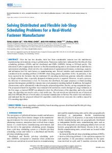
Fig. 1. Single line diagram of the micro-grid study system.
Motivated by the aforementioned difficulties, this paper presents an interactive DG interface for flexible micro-grid operation in smart distribution systems. The proposed control scheme utilizes a fixed hierarchical power–voltage–current control structure, which is used under different modes of operation. Therefore, only the magnitude of the reference voltage vector is subjected to variation, which minimizes the internal disturbances generated by switching a current-controlled interface to a voltage-controlled interface in conventional control techniques. The voltage controller is robustly designed to offer internal model control characteristics against random disturbances associated with mode transfer and harmonic and unbalanced voltage disturbances associated with DG operation under unbalanced voltages and nonlinear loads. Further, the proposed controller offers robustness against islanding detection delays due to the fixed control structure. Theoretical analysis and evaluation results verify the effectiveness of the proposed control scheme. II. SYSTEM CONFIGURATION Fig. 1 shows the micro-grid system under study, which is adapted from the IEEE 1559 standard for low voltage applications. The adopted study system represents a general low voltage distribution system, where different types of loads and different numbers of DG units can be considered to be connected to the main feeder. The DG units can be employed to work either parallel to the utility grid, or in isolated mode to serve sensitive loads connected to the main feeder when the main breaker (BR) is open. Without loss of generality, the performance of the micro-grid system is studied under the presence of two DG units, supplying general types of loads. The load on the second feeder is an inductive load where a 2.5-KVAr power factor correction capacitor bank is also considered to be connected to the main feeder. The adopted load
model is in line with the IEEE 1547 test load used in DG applications [17]. The nonlinear load is a three-phase diode rectifier with an load at the dc-side. The addition of the diode rectifier helps in assessing the effectiveness of the proposed controller in rejecting voltage harmonics associated with nonlinear loading, and rejecting load-DG-unit-grid interactions at harmonic frequencies. Power circuit and control parameters of DG units are given in the Appendix. The schematic diagram of a single DG unit as the building block of the sample micro-grid system is also shown in Fig. 1. When the DG unit is connected to the grid, the voltage and frequency at the point of common coupling are dominantly dictated by the grid. However, in case of weak grids, the voltage is prone to voltage sags and disturbances. In this case, the DG unit can be controlled to support the grid voltage. Therefore, both PQ and PV operational modes can be adopted in the grid-connected mode. Subsequent to an islanding event, DG units can form an autonomous micro-grid system to enhance the reliability of sensitive loads. This flexible operation requires robust control infrastructure, which is essential for system operators and supervisory controllers in the smart grid environment. In both grid-connected and isolated modes, the state space presentation of the DG interface dynamics can be given in the natural frame by
(1) where and are the filter inductance and capacitance, is the inverter output voltage, is the inverter output current, is the voltage at the point of common coupling, and is the network-side current. Note that , , and are 3 1 vectors representing phase quantities corresponding to each phase, and the filter-inductor resistance
KAHROBAEIAN AND MOHAMED: INTERACTIVE DG INTERFACE FOR FLEXIBLE MICRO-GRID OPERATION
297
the proposed design strategy, both external and internal disturbances can be eliminated or remarkably attenuated within the DG interface. Moreover, the fixed control structure increases the robustness of the control structure to islanding detection delays. The voltage control is designed by considering an augmented model that includes the -filter active damping and inner current control loop dynamics to ensure robustness and coordinated control design. Theoretical analysis and design procedure of the proposed control scheme are described in the following sections.
Fig. 2. Block diagram representation of the state space equations.
B. Resonance Damping is ignored. In order to decrease the number of differential equations and simplify system presentation, (1) can be rewritten in a stationary reference frame system by applying the following to transformation:
(2) Using (2), the state space model of the system in the is as follows:
frame
(3) Fig. 2 depicts the block diagram representation of the differential equations derived in (3) where models the exogenous disturbance caused by connecting the system to the utility grid. The block diagram suggests that the output current (i.e., ) can be regarded as an external disturbance caused by unknown load or grid behavior either in islanded or grid connected mode. Along with these exogenous disturbances, control mode switching in conventional DG controllers (e.g., from current control to voltage control) generates internal disturbances within the control structure. III. PROPOSED CONTROL SCHEME
Applying an filter at the output stage introduces a resonance peak to the frequency response of the system, which can limit the achievable bandwidth of the current controller in a multiloop hierarchical control approach. Besides, as the filter and grid parameters change, the corresponding resonance frequency also shifts, resulting in potential harmonic excitations at low-order harmonics affecting system stability. Therefore, converter resonance damping is essential to maintain stability and facilitate high bandwidth current control design. Active resonance damping can be a viable option, particularly in DG applications where losses associated with passive damping can reduce the generation efficiency. A simple and effective technique to actively damp filter resonance is to introduce a damping voltage that is proportional to the capacitor current. The dynamic equations corresponding to the actively damped system can be given as follows:
(4) where represents the current-dependent voltage source injected in series with the original inverter output voltage and is the virtual damping coefficient. With the active damping voltage modeled as a current-controlled voltage source, the open loop transfer function of the system of Fig. 1 is driven as (5)
A. Control Structure As indicated in Fig. 2, external disturbances will be imposed on the DG interface during mode transition and network/load disturbances. On the other hand, internal disturbances will be generated due to control function switching between different modes in the conventional hierarchical control structure. To overcome these issues and to achieve a flexible and robust operation of DG units under the smart grid environment while maintaining the hierarchical control structure, the proposed control scheme, shown in Fig. 3, utilizes a fixed hierarchical power–voltage–current control structure in both grid-connected and isolated modes. This will minimize the undesired voltage transients generated by switching from a current-controlled interface to a voltage-controlled interface in conventional control techniques. Further, the proposed power controller works under grid-connected and isolated micro-grid modes; this feature provides a flexible interface for the DG unit to be used in different operational modes with minimal switching. Due to
Fig. 4 shows the effect of introduced active damping on the open loop system frequency characteristics. The resonance peak can be completely damped, and accordingly high control bandwidth can be achieved. Based on the results provided in Fig. 4, can provide the desired damping performance. It can be noted that the introduced damping voltage is independent of the resonance frequency resulting in a robust damping performance under parameter variation. C. Augmented Internal Model-Based Voltage Control The main objective of the proposed voltage control scheme is to maximize the disturbance rejection performance for wide band of disturbances, and to meet the voltage tracking requirements. Towards this, a newly designed augmented internal model control (IMC) structure is proposed to provide internal model dynamics for harmonic, unbalanced, and random voltage disturbances.
298
IEEE TRANSACTIONS ON SUSTAINABLE ENERGY, VOL. 3, NO. 2, APRIL 2012
Fig. 3. Proposed control scheme.
regarded as an open loop system where the feed-forward compensator should be designed to ensure close tracking performance. On the other hand, disturbance rejection can be achieved via the feedback compensator design. Since the tracking and disturbance rejection performances can be designed independently, the IMC control scheme can be considered as a two-degree-of-freedom controller. The sensitivity function and the complementary sensitivity function , which represent tracking and disturbance rejection capabilities of the system, respectively, can be driven as follows: Fig. 4. Open loop frequency response of the actively damped system at dif. ferent values of
(6)
Fig. 5. Internal model control scheme.
Fig. 5 shows a general two degrees of freedom IMC structure [16]. In Fig. 5, represents a nominal model for the actual plant of , whereas and are feed-forward and feedback compensators, respectively, and can be regarded as the exogenous disturbance. Under exact model matching (i.e., ) and the absence of system disturbances, the feedback signal, which is influenced by the disturbance or any model uncertainties, would be zero. In this case, the IMC structure, shown in Fig. 5, can be
and such that The design goal is then to propose and within a reasonably large range of frequencies of interest. This will assure both disturbance rejection and tracking ability of the system. Assuming and , then the model following error is zero and the control scheme is reduced to an open loop one with . In this case, can provide a perfect tracking performance. Stability constraints require to be minimum phase. Besides, can be an improper transfer function and cannot be realized practically. Therefore, a lowpass filter is used to yield a proper feed-forward compensator (7) where corresponds to the bandwidth of the filter, and is an integer selected in such a way that is a proper or strictly proper function. The disturbance rejection is achieved via which produces a compensating input to cancel out disturbances. To overcome the computational burden associated with frame transformations, the proposed controller is performed in Clark’s -frame. Proportional resonant controller
KAHROBAEIAN AND MOHAMED: INTERACTIVE DG INTERFACE FOR FLEXIBLE MICRO-GRID OPERATION
299
with harmonic compensators (PRHC) are proposed to realize
(8) Fig. 6. Augmented plant model including active damping and inner current control loops.
In (8), the first term, , is the proportional resonant compensator with a proportional gain , and resonant gain , which is tuned at the fundamental angular frequency. The second term, , is the harmonic compensator, where denotes the harmonic order to be compensated and is the corresponding resonant filter gain. In and , is the cutoff frequency, which is introduced to facilitate practical implementation of resonant controllers under variation in the fundamental angular frequency (e.g., under isolated micro-grid operation). The PRHC provides high disturbance rejection gains at the fundamental and selected harmonic frequencies of the tracking error. Therefore, a wide range of disturbances can be effectively rejected. To cope with the hierarchical control structure, which inherently provides over-current protection, and enhances the dynamic performance of the system, the hierarchical design approach with the inductor inner current control loop should be considered in the voltage control design stage. Therefore, the inner current control and the proposed active damping dynamics should also be augmented in the earlier model introduced in Fig. 2. The augmented model with both current control and active damping dynamics is shown in Fig. 6, where and are used as feedback signals, respectively. In order to achieve a simpler expression for the augmented model, the inductor’s resistance is ignored. Due to the presence of the voltage controller in all modes of operation, a simple proportional current controller can be adopted as shown in Fig. 6. Note that the reference current in Fig. 6 is generated by the outer IMC-based voltage controller. The augmented model can be simplified as shown in Fig. 7, where models the transfer function between and in the presence of the active damping loop. The output/input transfer function in Fig. 7 can be given by
Fig. 7. Simplified block diagram of the augmented plant model.
Fig. 8. Hierarchical voltage control of the DG unit based on IMC scheme.
in (9) and the design approach introduced in (7), can be given by (10), shown at the bottom of the page, where subscript “ ” denotes nominal model parameters. It can be noted that the feed-forward compensator is both stable and proper. The time constant dictates the tracking bandwidth of the system. It can be also noted that mismatch in system parameters can be considered as disturbances and it will be attenuated by the feedback compensators. Therefore, robustness against parameter variation and disturbances can be yielded. The sensitivity transfer function of the proposed system, which represents the frequency response of the transfer function can be also obtained from Fig. 8 as follows: (11)
(9) Fig. 8 depicts the proposed IMC-based multiloop voltage control structure. Considering the output/input relation calculated
is the PRHC feedback compensator defined in (8). where Using the circuit and control system parameters of DG1, pro-
(10)
300
IEEE TRANSACTIONS ON SUSTAINABLE ENERGY, VOL. 3, NO. 2, APRIL 2012
Fig. 9. Frequency response for the (a) tracking and (b) disturbance rejection performances.
vided in the Appendix, the tracking and disturbance rejection characteristics of the suggested controller are demonstrated in Fig. 9(a) and (b), respectively. Fig. 9(a) implies that the proposed feed-forward compensator provides a very good tracking performance, which ensures minimum voltage tracking error. Fig. 9(b) shows how the proposed control structure can attenuate a wide range of random disturbances associated with the output current (e.g., voltage disturbances associated with mode transition). Further, due to the presence of the internal models tuned at harmonic frequencies, the proposed controller provides very high attenuation around the fundamental and selective harmonics (i.e., fifth, seventh, and eleventh).
Fig. 10. Three phase
-PLL with prenotch resonant filter.
D. Power Flow Control The adopted hierarchical design approach provides flexible operation of the DG unit in grid-connected mode. To minimize the control switching actions between grid-connected and isolated modes, a single active power control structure is used in both modes. The proposed active power controller, shown in Fig. 3, consists of a slow integrator, which generates frequency deviations according to the power-frequency characteristics presented in (12) (12) The above equation is very similar to the frequency-power droop equation in autonomous micro-grid system [6] and, therefore, by adopting an appropriate slope coefficient (i.e., ) based on a reasonably small frequency deviation range, the proposed real power controller can be used both in grid connected and islanded modes. Even if it is required to have different slopes at different modes, the control structure remains the same to minimize the generation of internal disturbances within the control structure. As shown in Fig. 3, in the grid-connected mode, the phase angle of the grid is generated via a three-phase phase-locked loop (PLL). A resonant filter tuned at the fundamental grid frequency is used along with the PLL to make
Fig. 11. Synchronization controller.
it more robust in the presence of voltage harmonics or unbalances [21]. On the other hand, during islanded operation, the processor internal clock is used to generate the aforementioned signal while is assumed to be . Considering the voltage and reactive power controller, the voltage amplitude can be either set to 1.0 p.u. for PV-bus operation, or it can be adjusted through a reactive power controller for PQ-bus operation. In the grid-connected mode, a proportional integral (PI) controller is adopted to provide the magnitude of the output voltage . Therefore, the voltage control signal can be generated as follows: (13)
KAHROBAEIAN AND MOHAMED: INTERACTIVE DG INTERFACE FOR FLEXIBLE MICRO-GRID OPERATION
301
Fig. 12. Dynamic response of the system to an active power command step change in grid connected mode and PQ operation. (a) Converter active power. (b) Converter reactive power. (c) Output voltage magnitude. (d) Instantaneous phase-a output voltage.
where are the proportional and integral gains, respectively, is the reference reactive power, and is the actual reactive power. In islanded operation, however, a voltage droop function is adopted to share the reactive power among different DG units. Accordingly, the voltage magnitude is generated according to
micro-grid system employs two DG units, which can work parallel to the utility grid, or in isolated mode when the grid is not available to serve sensitive loads. The proposed flexible control structure, shown in Fig. 3, makes it possible for the DG unit to support the grid in different scenarios. Different scenarios are tested. Key results are presented as follows.
(14) A. Grid-Connected Mode where
is the reactive power droop gain.
E. PLL Configuration and Synchronization Fig. 10 shows the configuration of the adopted prefiltered three-phase -PLL for the synchronization purpose in the grid connected mode [21]. This is a standard -PLL with a resonant filter added to make it more robust in the presence of voltage harmonics and unbalance. The islanded operation is inevitable when there is a grid failure or blackout; however, when the grid voltage is back to its normal condition, a synchronization process is required before transition to the grid connected mode. In order to bring the output voltage angle to the grid angle, which is estimated by the adopted PLL, a synchronization controller, shown in Fig. 11, can be realized by applying small frequency deviations in the voltage command to decrease the phase mismatching between the two voltages. The DG unit would connect to the grid when the angle difference is sufficiently lower than a threshold tolerance to ensure seamless connection with respect to the phase angle. IV. RESULTS To evaluate the performance of the proposed control scheme, the study system depicted in Fig. 1 is implemented for time domain simulation under the Matlab/Simulink environment. The
Fig. 12 shows the control performance under PQ-bus operation mode for one of the DG units. The inductive load and the capacitor bank are activated in this scenario. The reactive power command is set to zero, whereas the active power command experiences a step change from 5 to 10 kW at s. Fig. 12(a) and (b) shows the active and reactive powers generated by the unit. Close active power tracking performance is yielded. On the other hand, the coupling between active and reactive power dynamics is minimal. Fig. 12(c) depicts how the output voltage amplitude changes to maintain the unity power factor condition while increasing the active power injection. Voltage fluctuation in this mode is the natural result of the absence of voltage control at the point of common coupling. The instantaneous phase- output voltage is shown in Fig. 12(d). In addition to active power regulation, the DG unit can contribute to the voltage reliability at the point of common coupling by allowing bus voltage control (i.e., PV mode). This mode can be activated once voltage sags (e.g., due to upstream faults) are detected. Under these conditions, the voltage control mode is activated to inject reactive power during the sag period to provide fault-ride-through performance. Accordingly, the economic operation of the DG unit will not be compromised. On the other hand, in long radial feeders and weak grids, existing DG units can be used for continuous voltage support. Fig. 13 shows the effectiveness of the proposed control strategy in terms of providing the DG unit with the fault-ride-through capability. The
302
IEEE TRANSACTIONS ON SUSTAINABLE ENERGY, VOL. 3, NO. 2, APRIL 2012
Fig. 13. Dynamic response of the system under 10% grid voltage sag under PV-bus operation. (a) Instantaneous and feeder voltage in p.u. (c) Converter reactive power.
output voltage. (b) DG output voltage (blue)
Fig. 14. Dynamic response of the system when a nonlinear load is added in grid connected mode. (a) Phase- output voltage. (b) Phase- load current (c) PLL output.
grid voltage encounters a 10% sag from s to s due to an upstream fault in the main feeder. The – – load is assumed to be the locally connected load. Fig. 13(a) shows the phase- voltage during the voltage disturbance. Fig. 13(b) shows the magnitude of the output voltage of the DG unit and the main feeder. Fig. 13(c) shows the reactive power injected by the unit during the fault period. Provided that there is enough reactive power rating, larger voltage sags can be mitigated by the DG interface. To test the disturbance rejection against loading transients and harmonic loading, the nonlinear load is switched ON at s. The controller response to the addition of the nonlinear load is shown in Fig. 14. Fig. 14(a) shows the output voltage waveform of phase- , whereas Fig. 14(b) shows the load current. The proposed controller acts fast enough to reject the sudden loading disturbance yielding close voltage regulation at the local ac bus voltage. On the other hand, the harmonic disturbance rejection ability of the proposed controller is obvious. In spite of the heavily distorted load current, the total harmonic distortion (THD) of the phase- voltage is 0.67% and
0.81% before and after adding the nonlinear load, respectively. The PLL output in the presence of harmonics is also shown in Fig. 14(c). Note that the PLL output is robust even after adding the rectifier load to the system. This is because of the resonant filter which provides robust phase tracking in the presence of harmonics. These results confirm the high disturbance rejection performance of the proposed controller. B. Isolated Mode The transitional performance of the study system under the proposed control scheme from grid connected to islanded mode is evaluated by emulating an islanding event via opening the breaker switch (BR) at the upstream feeder in Fig. 1. Initially, the micro-grid system is connected to the grid and both DG units are working in the PV-bus mode. The study system is islanded at s by opening the breaker BR. In this paper, the smart distribution study system is assumed to be equipped with a power line communication-based islanding detection scheme [19], [20], where the islanding event is detected with
KAHROBAEIAN AND MOHAMED: INTERACTIVE DG INTERFACE FOR FLEXIBLE MICRO-GRID OPERATION
303
Fig. 15. Dynamic response of the two-DG micro-grid system due to an islanding event with DG units acting as PV buses. (a) Instantaneous phase- grid voltage with and without proposed controller. (b) RMS feeder voltage with proposed controller. (c), (d) Active and reactive converter powers of each DG unit.
Fig. 16. Dynamic response of the two-DG micro-grid system due to an islanding event with DG units acting as PQ buses. (a) Instantaneous phase- grid voltage with and without proposed controller. (b) RMS feeder voltage with proposed controller. (c), (d) Active and reactive converter powers of each DG unit.
some communication delays after the upstream feeder breaker goes open and this event is signaled to the supervisory control unit shown in Fig. 3. The detection delay is assumed to be 20 ms; therefore, the islanding event is detected at s. Fig. 15 depicts the dynamic response of the system prior to and after the islanding event. DG units utilize the same control structure, which is applied for both grid connected and islanded modes. Reactive power sharing is adopted in the isolated mode. The load voltage waveform and magnitude are shown in Fig. 15(a) and (b), respectively. In Fig. 15(a), the voltage response associated with the conventional method (i.e., switching from current-controlled to voltage-controlled interface) is also shown. As it can be seen, without applying the proposed method, the system is experiencing much higher over voltages due to the internal disturbance generated by switching from current-controlled interface to a voltage-controlled one, and thus implying the effectiveness of the adopted control scheme.
Fig. 15 confirms that the proposed controller is well capable of maintaining the load voltage subsequent to an islanding event. The dynamics responses of the active and reactive power components for each DG unit are shown in Fig. 15(c) and (d), where the initial active power generated by each DG is 5 kW, dictated by the power controller in the grid connected mode. However, subsequent to the islanding event, the generated active power is decreased in order to meet the load consumption (i.e., 8.0 kW). The robustness of the proposed controller under micro-grid operation is obvious. For further performance evaluation, the micro-grid system is connected to the grid and both DG units are working in the PQ-bus mode (with unity power factor). The utility supply is lost at s. The islanding is detected after 20 ms by the supervisory control unit at s. Fig. 16 depicts the dynamic response of the system prior and after the islanding event. The load voltage waveform and magnitude are shown in
304
IEEE TRANSACTIONS ON SUSTAINABLE ENERGY, VOL. 3, NO. 2, APRIL 2012
Fig. 17. Dynamic response of the system when a nonlinear load is added in islanded mode. (a) Instantaneous phase- output voltage. (b) Phase- load current. Instantaneous phase- grid current. (c), (d) Active and reactive converter powers for DG1. (e), (f) Active and reactive converter powers for DG2.
Fig. 18. Dynamic response of the two-DG micro-grid system when reconnecting to the utility as PQ buses. (a) Instantaneous phase- grid current. (b) Instantaneous phase- output voltage. (c), (d) Active and reactive converter powers for each DG unit.
Fig. 16(a) and (b), respectively. Close voltage control characteristics are yielded subsequent to the islanding event. Once again the system response in the absence of the proposed scheme is shown in Fig. 16(a), where the higher transient over-voltage is obvious. The active and reactive power responses for DG units are shown in Fig. 16(c) and (d), where the initial active power generated by each DG is 6.0 kW at unity power factor. Subsequent to the islanding event, the generated active power decreases in order to meet the load demand. Fig. 17 shows the load voltage and current responses of the islanded system when the nonlinear load is added at s. Fig. 17(a) shows the load voltage, whereas Fig. 17(b) shows the load current. It can be seen that the controller is well capable of
maintaining the output voltage quality despite the highly distorted current going through the load. The THD of the load voltage is 2.7%. Fig. 17(c)–(f) shows the active and reactive power profiles of both DG units. Accurate power sharing performance is yielded even in the presence of harmonic loading, which demands reactive power injection by both DG units. Fig. 18 shows the grid current, the load voltage, and power responses during a supply restoration scenario at s. Once the utility supply is restored, both DG units operate as a PQ bus with unity power factor and with a power command of 3.0 kW for each unit. In spite of grid-current transients, the load voltage is closely controlled to facilitate seamless restoration. Similar to the micro-grid formation event, the proposed con-
KAHROBAEIAN AND MOHAMED: INTERACTIVE DG INTERFACE FOR FLEXIBLE MICRO-GRID OPERATION
trol scheme yields seamless connection performance under the supply restoration event by rejecting the generated disturbances internally and externally within the control structure. V. CONCLUSION An interactive DG interface for flexible micro-grid operation in the smart distribution system environment has been presented in this paper. The proposed control scheme utilizes a fixed power–voltage–current cascaded control structure with robust internal model voltage controller to maximize the disturbance rejection performance within the DG interface, and to minimize control function switching. The proposed control scheme has a simple and linear control structure that facilitates flexible DG operation in the grid-connected mode and autonomous micro-grids, yields robust transition between grid-connected and islanded modes either in PQ or PV operational modes, and provides robustness against islanding detection delays due to the fixed control structure under different modes of operation. Therefore, the proposed control scheme enhances the flexibility of micro-grid operation under the dynamic nature of future smart distribution systems. APPENDIX The parameters of the test system shown in Fig. 1 and converter control parameters are given as follows: DG1 and DG2: mH, , F, , , , , , , rad/W, V/VAR, , , rad/s, rad/s, switching frequency kHz, PLL loop filter: proportional gain: 50, integral gain: 100. REFERENCES [1] Smart Grid: An Introduction U.S. Department of Energy, 2009. [2] E. M. Lightner and S. E. Widergren, “An orderly transition to a transformed electricity systems,” IEEE Trans. Smart Grid, vol. 1, no. 1, pp. 3–10, Jun. 2010. [3] K. Moslehi and R. Kumar, “A reliability perspective of smart grid,” IEEE Trans. Smart Grid, vol. 1, no. 1, pp. 57–64, Jun. 2010. [4] G. T. Heydt, “The next generation of power distribution systems,” IEEE Trans. Smart Grid, vol. 1, no. 3, pp. 225–235, Nov. 2010. [5] A. Timbus, M. Liserre, R. Teodorescu, P. Rodriquez, and F. Blaabjerg, “Evaluation of current controllers for distributed power generation systems,” IEEE Trans. Power Electron., vol. 24, no. 3, pp. 654–664, Mar. 2009. [6] J. M. Guerrero, J. C. Vasquez, J. Matas, K. Vicuna, and M. Castilla, “Hierarchical control of droop-controlled ac and dc microgrids—A general approach towards standardization,” IEEE Trans. Ind. Electron., to be published. [7] M. Liserre, R. Teodorescu, and F. Blaabjerg, “Multiple harmonics control for three-phase grid converter systems with the use of PI-RES current controller in a rotating frame,” IEEE Trans. Power Electron., vol. 21, no. 3, pp. 836–841, May 2006. [8] Y. A.-R. I. Mohamed, “Mitigation of dynamic, unbalanced and harmonic voltage disturbances using grid-connected inverters with LCL filter,” IEEE Trans. Ind. Electron., vol. 58, no. 9, pp. 3914–3924, Sep. 2011. [9] S. Ahn, “Power-sharing method of multiple distributed generators considering modes and configurations of a microgrid,” IEEE Trans. Power Del., vol. 25, no. 3, pp. 2007–2016, Jul. 2010.
305
[10] Twinning and D. G. Holmes, “Grid current regulation of a threephase voltage source inverter with an LCL input filter,” IEEE Trans. Power Electron., vol. 18, no. 3, pp. 888–895, May 2003. [11] D. De and V. Ramanarayanan, “Decentralized parallel operation of inverters sharing unbalanced and nonlinear loads,” IEEE Trans. Power Electron., vol. 25, no. 12, pp. 3015–3022, Dec. 2010. [12] H. Kim, T. Yu, and S. Choi, “Indirect current control algorithm for utility interactive inverters in distributed generation systems,” IEEE Trans. Power Electron., vol. 23, no. 3, pp. 1342–1347, May 2008. [13] Z. Yao, L. Xiao, and Y. Yan, “Seamless transfer of single-phase gridinteractive inverters between grid connected and stand-alone modes,” IEEE Trans. Power Electron., vol. 25, no. 6, pp. 1597–1603, Jun. 2010. [14] F. Gao and R. Iravani, “A control strategy for a distributed generation unit in grid-connected and autonomous modes of operation,” IEEE Trans. Power Del., vol. 23, no. 2, pp. 850–859, Apr. 2008. [15] Y. A.-R. I. Mohamed and A. Radwan, “Hierarchical control system for robust micro-grid operation and seamless mode-transfer in active distribution systems,” IEEE Trans. Smart Grid, vol. 2, no. 2, pp. 352–362, Jun. 2011. [16] M. Morari and E. Zafirious, Robust Process Control. Englewood Cliffs, NJ: Prentice-Hall, 1989, ch. 2–3. [17] F. Blaabjerg, R. Teodorescu, M. Liserre, and A. V. Timbus, “Overview of control and grid synchronization for distributed power generation systems,” IEEE Trans. Ind. Electron., vol. 53, no. 5, pp. 1398–1409, Oct. 2006. [18] Draft Guide for Design, Operation, and Integration of Distributed Resource Island Systems With Electric Power Systems, IEEE P1547.4. [19] W. Xu, G. Zhang, C. Li, W. Wang, G. Wang, and J. Kliber, “A powerline signalling based technique for anti-islanding protection of distributed generators–Part I: Scheme and analysis,” in Proc. 2007 IEEE Power Engineering Society General Meeting, Jun. 24–28, 2007, p. 1. [20] M. A. Redfern, O. U. Usta, and G. Fielding, “Protection against loss of utility grid supply for a dispersed storage and generation unit,” IEEE Trans Power Del., vol. 8, no. 3, pp. 948–954, Jul. 1993. [21] Y. A.-R. I. Mohamed, “Mitigation of grid-converter resonance, grid-induced distortion and parametric instabilities in converter-based distributed generation,” IEEE Trans. Power Electron., vol. 26, no. 3, pp. 983–996, Mar. 2011.
Alireza Kahrobaeian received the B.Sc. and M.Sc. degrees in electrical engineering from the University of Tehran, Tehran, Iran, in 2007 and 2010, respectively. He is currently working toward the Ph.D. degree at the University of Alberta, Edmonton, AB, Canada. His research interests include control and stability analysis of micro-grids and smart grid systems.
Yasser Abdel-Rady I. Mohamed (M’06–SM’11) was born in Cairo, Egypt, on November 25, 1977. He received the B.Sc. (with honors) and M.Sc. degrees in electrical engineering from Ain Shams University, Cairo, in 2000 and 2004, respectively, and the Ph.D. degree in electrical engineering from the University of Waterloo, Waterloo, ON, Canada, in 2008. He is currently with the Department of Electrical and Computer Engineering, University of Alberta, AB, Canada, as an Assistant Professor. His research interests include dynamics and controls of power converters; distributed and renewable generation; modeling, analysis and control of smart grids; and electric machines and motor drives. Dr. Mohamed is an Associate Editor of the IEEE TRANSACTIONS ON INDUSTRIAL ELECTRONICS. He is also a Guest Editor of the SPECIAL SECTION ON DISTRIBUTED GENERATION AND MICRO-GRIDS, IEEE TRANSACTIONS ON INDUSTRIAL ELECTRONICS. His biography is listed in Marquis Who’s Who in the World.