In: IEEE International Conference on Robotics and Automation, 1998. Interactive Generation of ... the Programming by Demonstration (PbD) paradigm that were ...
In: IEEE International Conference on Robotics and Automation, 1998
Interactive Generation of Flexible Robot Programs H. Friedrich
J. Holle R. Dillmann University of Karlsruhe Institute for Process Control & Robotics D-76128 Karlsruhe, Germany
Abstract Service robots require interactive programming interfaces that allow users without programming experience to easily instruct the robots. Systems following the Programming by Demonstration (PbD) paradigm that were developed within the last years are getting closer to this goal. However, most of these systems lack the possibility for the user to supervise and alter the course of program generation after the initial demonstration was performed. In this paper we present an approach, where the user is able to supervise the entire program generation process and to annotate, and edit system hypotheses. Moreover, the knowledge representation and algorithms presented enable the user to generalize the generated program by annotating conditions and object selection criteria via a 3D simulation and graphical user interface. The resulting PbD-system widens the PbD approach in robotics to the interactive generation of exible robot programs based on demonstration and annotations.
1 Introduction
The development of service robots is one of the main topics in robotics research. One of the major problems to be solved in order to successfully apply manipulators to service tasks is the problem of enduser programming. Interactive programming interfaces are required that allow users without programming education to easily instruct a robot. In the last years several robot programming systems were developed that follow the Programming by Demonstration (PbD) paradigm [8, 9, 10, 3]. Most of these systems are focused on the task of reconstructing the trajectories and manipulations a user performs. Their goal is to reconstruct the demonstrations with the highest accuracy possible, processing sensor data from multiple vision systems, laser sensors, structured
light, and in some cases especially designed input devices. In general these systems have three characteristics, that draw limits to their applicability to end-user programming end service tasks. 1. Most of them don't allow or require further interaction of the user in the programming process, than just the physical demonstration itself. This limits the information available to the programming system to the trajectories of the users extremities and the objects and there properties. The user's intention that stands behind the observable actions has to be guessed or is not taken into account at all. 2. The systems do not provide any supervision and monitoring interfaces for the user besides the actual execution of the generated program itself. Thus, wrong system hypotheses derived in the beginning of the program generation process can't be identi ed and corrected. 3. The generated programs are either in exible to changes in the execution against the demonstration environment since the program accurately replicates the user's demonstration, or they are generalized based on heuristics or inductive learning techniques without really knowing the user intentions. Summarizing part of the state of the art systems are either very sophisticated accurate visual teaching systems which are easy and comfortable to use. The others do allow the generation of exible robot programs but do not guarantee that these match the users' intentions. Both results are not ful lling the requirements posed by service robot programming. Besides accuracy understandability, and exibility are the major requirements to be met. In exible programs will fail in dynamic service environments and exible programs whose accordance with the user intentions is not
guaranteed are not acceptable if not even potentially dangerous. In the following an approach is presented that allows the representation of actions with di�erent levels of accuracy, as well as the exible representation of object selection criteria for program execution. Thereafter, a method is given that allows the generation of programs following several processing and user interaction phases starting with the initial user demonstration.
2 Program Representation
The basic requirement for service task programs is the adaptability of the program to the user's needs and intentions. This means, that a generated program has to be as accurate as required and as exible as possible. Therefore, important features of the program representation are the following. 1. It has to be interpretable by the user. 2. Actions have to be represented accurately, but also exible to changes in object locations at execution time. 3. It has to contain object selection criteria that allow the instantiation of the objects to be manipulated in di�erent environments. In order to cover all of these aspects the developed representation combines
� the use of exible object selection criteria given as logic terms based on spatial relations,
� the object relative representation of trajectory segments by employing a frame notation,
� the representation of exact geometric object con gurations, and
� exible representation of trajectory segments
w.r.t. accuracy by using a set of elementary motion and grasping operations.
Moreover, adding a conjunction speci es an alternative environmental state in which the program or one of its sub-steps shall be executed. In the developed system well-known spatial relations as in; on; aligned, and object related relations like type; colour; lot are used to semantically model and describe object con gurations and features that represent object selection criteria and thus carry the user intention. The set of relations and features can easily be extended and exchanged for di�erent tasks that are to be programmed, e.g. one could use contact relations as proposed by Ikeuchi [5]. To add other object related relations regarding speci c product oriented information like stiffness or roughness is straight forward either. Thus the means available for describing object selection criteria and thereby representing the user intention can easily be tailored to the speci c task requirements. Object relative trajectory representation allows the storage of trajectories in an object dependent way. Each frame which is to be visited in the course of following the trajectory is given relative to an object using a common frame notation. If for example a spacer is to be picked up, the trajectory to the spacers location is given relative to it. Each sample is given in the form (spacer T ), where spacer denotes the object and T the frame relative to the object. In case of an execution the trajectory towards the object is driven as desired, regardless whether the object is situated at exactly the same location as during demonstration or not. Exact geometric object con gurations of multiple objects are often required to ful ll certain tasks. If this is the case, the qualitative propositions that are given by the object selection criteria terms alone do not su�ce to represent the user's intention and/or task requirements. Therefore the developed program representation allows the geometrically exact representation of object con gurations. Transformation matrices T1; � � � ; Tn from the local object coordinate systems of all objects O1 ; � � � ; On involved to a single frame F are computed and stored. Obviously, the following equation holds, were TO denotes the transformation from the world coordinate system to the local coordinate system of object Oi . i
Object selection criteria are the key to program
generalization, instantiation and execution in di�erent environments. The object selection criteria are represented for each object by logic terms given as disjunctive normal form of relations. This representation is very e�cient. Firstly, it allows the easy adjustment of a programs applicability and therefore exibility to the user's intention by adding or deleting relations.
F = T1 � TO1 = T2 � TO2 = � � � = Tn � TO
n
(1)
In an execution environment the objects chosen as candidates for manipulation based on the object selection criteria can be checked against the condition given with equation 1. If the equation holds with the chosen
objects, their geometric con guration is the same as the one that was present in the demonstration environment. If not, the chosen set of objects is an invalid instantiation of the program. By adding tolerance values to the representation permitted translational and rotational deviations in object con gurations are modeled. Geometric object con gurations represented as described are called path contexts. Scalable accuracy and exibility of the actions performed in the course of program execution is achieved, by mapping the user demonstration on a set of Elementary Operations (EOs). Using this concept [4] provides several advantages. Firstly, standard robot motion commands can be used, e.g. linear ; move; spline ; move etc., which eases the mapping of a demonstration on standard manipulators. Secondly, the accuracy of the trajectory representation and the required memory can be adjusted to the user's intention. An exact ; move, that exactly replays the original trajectory provides the highest accuracy. On the other hand it also requires the most memory, since each sample has to be stored. Besides motion operations also di�erent grasp operations can be represented by di�erent operators. In principle, di�erent grasp hierarchies [1, 6] can easily be used by implementing operators for these. In order User
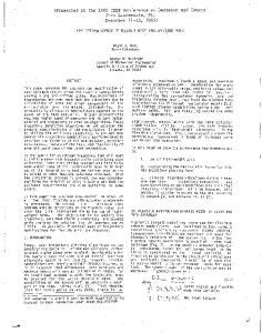
Processing steps
supervision/correction or interactive segmentation
trajectory segmentation at grasp/ungrasp
time
map segments on EOs
object selection
create geometric contexts
object & relation selection
create selection criteria
The developed system uses a 22 sensor data glove and magnetic eld based 6D position sensor to record the physical user demonstration. Therefore, the trajectory of the user's motions and his ngers' poses are given directly but due to the position sensor with limited accuracy. However, in principle the methods presented work on all trajectories, regardless whether they were recorded with a position sensor or whether they were derived from highly accurate vision or laser based sensor recordings.
Data-bases
Sensor data
analysis of segments supervision/correction
3 Trajectory Analysis
EOs
Figure 2: Trajectory sampled with 20Hz Figure 2 shows the trajectory recorded from the demonstration of a bag packaging task, where 3 infusion bags were stacked in a cardboard box. The nal con guration of the bags is shown in gure 3
Worldmodel
program generation
Programs
Figure 1: Interactive programming process exploit the bene ts of the presented program representation, a method is required that processes recorded sensor data of a user given demonstration and generates a program using the developed representation that matches the user intention. The general processing steps of the method we propose are given in gure 1.
Figure 3: Final world state of bag packaging task
Trajectory segmentation is done in order to di-
vide the demonstration in meaningful phases that are associated to the di�erent manipulations that the user performed. Grasp recognition is to be performed in order to segment the trajectory. In the system two methods for grasp recognition and thus trajectory segmentation were implemented. Firstly, user interactive recognition in which the demonstration is replayed in 3D simulation. The user presses a button when grasps or ungrasps occur. By analyzing the velocity and acceleration trajectories w.r.t. to minima in a window around the chosen sample, the grasp/ungrasp points are set. The second method is based on neural net classi ers that correspond to the grasp types given in Cutkosky's grasp hierarchy [1]. Grasp and ungrasp hypotheses are drawn from the nger poses and veri ed with collision detection algorithms on the world model that also provides the identi ers of the grasped objects. Segment-wise trajectory analysis follows the segmentation. The identi ed segments between grasp/ungrasp operations are analyzed w.r.t. almost linear subsegments in these. The analysis is performed with the iterative end-point t algorithm [7] which originally was an edge reconstruction algorithm for sensor data processing. For this task the algorithm was extended from handling 2D to 3D data. As result the processed trajectory segment is given in a piecewise linear representation. The resulting set of lines is shown in gure 4.
Figure 4: Results of the trajectory analysis
Mapping the trajectory segments on EOs is a crucial step, since here the accuracy of the trajectory the program will contain is determined. The system generates hypotheses regarding the desired accuracy of reconstruction based on the the speed and acceleration
trajectory w.r.t. the corresponding space trajectory, and the length and direction changes of the successive lines that were identi ed in the previous steps. Currently, hypotheses regarding linear ; moves and free ; moves are generated, where linear ; moves are characterized by low speed and accelerations on the according linear segments. Thereafter, the hypotheses are presented to the user giving him the possibility to acknowledge or edit the system's choices using the comfortable menu and 3D simulation based interface shown in gure 5. The data stored varies for di�erent EOs. For free ; moves and linear ; moves only start and end points of the corresponding line are stored, whereas for a spline ; move the end points of all included lines are stored as intermediate points of the spline. The most accurate representation of the demonstration trajectory is achieved using exact ; moves. For these all samples of the demonstration trajectory that are included in the chosen segment are stored. The modular design of the system allows the easy extension with more EOs that might be needed for di�erent tasks, e.g. circular ; move or insertion.
4 Acquisition of User Intention
During execution it has to be ensured, that the objects chosen for manipulation and con gurations chosen as destinations match with the user intentions. This is essential, since at execution time multiple objects in di�erent locations and con gurations could serve as candidates for manipulation. Therefore, following, the representation of the trajectory with the user intended accuracy, the object selection criteria and exact geometric object con gurations have to determined in order to guarantee correct instantiation in case of execution. Since the required information can't be guessed by the programming system it has to be acquired from the user. Path contexts that have to be speci ed in order to represent required exact geometric object con gurations are acquired employing a menu based graphical interface, as well as the 3D simulation. The user can choose for which grasp/ungrasp phase he wants to specify the path context, and what tolerance values shall be stored. The objects involved in the object con guration related to the path context are chosen by simply clicking on them in the simulation environment. Thereafter, the system calculates the transformation matrices relative from the objects to the grasp/ungrasp frame as present in the demonstration data. Finally, the com-
Figure 5: Interactive acknowledgment and editing of EO mapping pletely speci ed path context is stored in the respective grasp/ungrasp EO.
Figure 6: Criterion for the nal ungrasp action
Object selection criteria are also to be acquired
for each grasp/ungrasp phase. For grasp phases they serve as representation of the spatial conditions an object has to be in and the features it has to have in order to be a candidate for manipulation during program execution. For ungrasp phases they do describe the spatial object con guration the currently manipulated object is to be put in and the features of the objects building this con guration. Since the computation of all valid relations between all objects in the environment would be very time consuming, and the selection among these by the user would be very uncomfortable for him, the user is asked to specify signi cant object and relations in advance. Therefore, the objects involved in the spatial context are chosen by the user by simply clicking on them in the simulation. Thereafter, the user chooses the object features and spatial relations that are of general interest in the context at hand from menus of the user interface. Based on the speci ed sets of objects and relations the system computes the values for all relations and permutations of objects. The result of this computa-
tion is presented to the user in an interface menu that allows the speci cation of object selection criteria, by consecutively selecting relations from the menu and adding them to the already selected ones. In order to clarify the meaning of spatial relations and to point out the objects involved, the concept of 3D-Icons [2] is used. The user can trigger this visualization of relations (see g. 7), whenever in doubt about their semantics or the related objects. Finally, when an object selection criterion is completely speci ed (see g. 6), the programming system stores it in the respective slot of the program representation. Thereafter, the program is complete and the generated operator sequence is stored in the program database for further use.
5 Summary and Conclusion
In this paper a program representation was presented that is based on a set of elementary operations, that ful lls the requirements of service task programming. It provides freely scalable accuracy and exibility of the stored trajectories. Flexible representation of conditions specifying required geometric and spatial object con gurations and required object features allow the instantiation of generated programs in different environments. Furthermore an interactive programming system was presented that generates programs in the developed representation in a sequential process based on a physical user demonstration and annotations. All processing and programming steps can be monitored and in uenced by the user. System hypotheses regarding motions, conditions, etc. are to be acknowledged, edited or actively speci ed using a comfortable menu driven user interface and direct interaction with a 3D
Figure 7: Visualizing the aligned(bag1; bag3) relation with a 3D-icon simulation environment. The presented representation together with the interactive programming system is an extension of the currently available methods and systems towards more
exible end-user programming. It is not only concentrating on the exact replication of a physical demonstration but also taking into account and representing the user's intention.
Acknowledgments
This work has partially been supported by the DFG Project "Programmieren durch Vormachen". It has been performed at the Institute for Real-Time Computer Systems and Robotics, Prof. Dr.-Ing. H. Worn, Prof. Dr.-Ing. U. Rembold and Prof. Dr.-Ing. R. Dillmann.
References [1] M.R. Cutkosky. On grasp choice, grasp models, and the design of hands for manufacturing tasks. IEEE Trans. Robotics and Automation, 5(3):269{279, 1989. [2] H. Friedrich, H. Hofmann, and R. Dillmann. 3dicon based user interaction for robot programming by demonstration. In Proceedings of the International Symposium on Computational Intelligence in Robotics and Automatio (CIRA`97), Monterey, USA, 10-11 July 1997. [3] H. Friedrich, S. Munch, R. Dillmann, S. Bocionek, and M. Sassin. Robot programming by demonstration: Supporting the induction by human interaction. Machine Learning, pages 163{189, May/June 1996. [4] H. Friedrich, O. Rogalla, and R. Dillmann. Integrating skills into multi-agent systems. Journal of Intelligent Manufacturing, 1998. to appear.
[5] Katsushi Ikeuchi and Takashi Suehiro. Assembly task recognition using face-contact relations. In Proceedings of the IEEE International Conference on Robotics and Automation (ICORA`92), volume 3, pages 2171{2177, Nice, France, 1992. [6] Sing Bing Kang and Katsushi Ikeuchi. A grasp abstraction hierarchy for recognition of grasping tasks from observation. In Proceedings of the IEEE/RSJ International Conference on Intelligent Robots and Systems (IROS`93), volume 1, pages 621{628, Yokohama, Japan, July 26-30 1993. [7] T. Knieriemen. Autonome Mobile Roboter - Sensordateninterpretation und Weltmodellierung zur Navigation in unbekannter Umgebung, volume 80 of BI - Wissenschaftverlag. K.H. Bohling, U. Kulisch, H.Maurer, 1991. [8] Yasuo Kuniyoshi, Inaba Masayuki, and Hirochika Inoue. Learning by watching: Reusable task knowledge from visual observation of human performance. IEEE Transactions pn Robotics and Automation, 10(6):799{ 822, December 1994. [9] George V. Paul and Katsushi Ikeuchi. Modelling planar assembly tasks: Representation and recognition. In Proceedings of the IEEE/RSJ International Conference on Intelligent Robots and Systems (IROS`95), volume 1, pages 17{22, Pittsburgh, PA, USA, Aug. 5-9 1995. [10] Tomoichi Takahashi. Time normalization and analysis method in robot programming from human demonstration data. In Proceedings of the IEEE International Conference on Robotics and Automation (ICORA`96), volume 1, pages 37{42, Minneapolis, Minnesota, USA, April 1996.