Optimal Multi-Distributed Generation Location and Capacity by Genetic Algorithms M.H.Moradi
M.Abedinie
H. bagheri tolabi
University of Bu Ali Sina Hamadan, Iran
[email protected]
University of Bu Ali Sina Brojerd, Iran
[email protected]
Islamic Azad University Khorramabad, Iran
[email protected]
Abstract— This paper proposes Genetic Algorithms (GA) for solving optimal multi-distributed generation (DG) location and capacity. The objective is to minimize the real power loss within security and operational constraints. Four kinds of DG are considered including distributed real power sources only, distributed real reactive sources only, distributed generation supplying real power and consume reactive power, distributed generation supplying real power and reactive power, representing photovoltaic, synchronous condenser ,wind turbines, and hydro power, respectively. A detailed performance analysis is carried out on 33 bus system to demonstrate the effectiveness of the proposed methodology.
generation going on line. It is predicted that they would have about 20% of new generations being installed [3]. They use different types of resources and technologies to serve energy to power systems. DG applications result in positive and negative side effects for both utility and customers [4], [5]. While DG has shown its contributions to an improved power quality, the extent of effects varies depending on the placement of a DG in the network. Different design strategies for Distributed Generation in modified IEEE 14 bus test case [6], are studied and compared in terms of power loss reduction, load ability, and voltage stability index.
Keywords— Distributed generation, Genetic algorithm, Placement, Losses
In order to achieve the aforementioned benefits, the DG size has to be optimized. The optimal DG size is dealt with as a nonlinear programming (NLP) problem with both nonlinear objective function and constraints. Such DG NLP problem was solved via heuristic and deterministic techniques. The heuristic methods utilized in the attempt of solving the DG optimal size were Genetic Algorithm (GA) [7; 8], hybrid GA – Fuzzy [9; 10] and Particle Swarm Optimization [11].
I.
INTRODUCTION
Distribution systems are usually radial in nature for operational simplicity. The Radial Distribution Systems (RDS) are fed at only one point, which is the substation. The substation receives power from the centralized generating stations through interconnected transmission network. The end users of electricity receive electrical power from the substation through RDS, which is a passive network. Hence, the power flow in the RDS is unidirectional. The high R/X ratio of the distribution lines results in large voltage drops, low voltage stability and power losses. Under critical loading conditions in certain industrial areas, RDS experiences sudden voltage collapse due to low value of voltage stability index at most of its nodes. Recently, several solutions have been suggested for complementing the passiveness of RDS by embedding electrical sources of small capacity to improve system reliability and voltage regulation [1], [2].
Most of the techniques in the literature are aimed at optimize either location or capacity and to estimates the benefits resulting from that like voltage improvement, loss reduction, location marginal prices [12]. This paper proposes optimization of both location and capacity of multiple distributed generation sources by accounting technical using Genetic Algorithm. The minimum objective function of network loss is:
{
}
, ,…, (1) Min .f = min stands for the rating capacity of distributed generation is the system network loss in fixing in the i bus; where relation to dynamoelectric location and capacity. The limited condition of equation is the systematic power that comes from distributed generation connecting to distribution network. The limited in equations include: upper and lower limit of bus voltage, largest limit of branch power, upper and lower limit of distributed-generation capacity.
Such embedded generations in the distribution system are called as dispersed generations or distributed generations (DG). Distributed energy systems can provide solution to many power system problems. Distributed Generation (DG) has proven to effectively improve power system stability, power quality, energy efficiency, and help environmental protection. Distributed generation is expected to play an increasing role in emerging electric power systems. Studies have predicted that DG will be a significant percentage of all new
978-1-4244-7398-4/10/$26.00 ©2010 IEEE
PROPOSED METHODOLOGY
II.
614
IPEC 2010
IV.
Equations (2) and (3) are well-known load flow equations. ∑ ∑
0
(2)
0
(3)
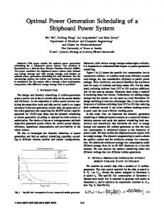
A. Fig 1 shows the flow chart optimal sitting and sizing of distributed generation.
Initial set of random control variable settings (solution)
The generator voltage will be the load/bus voltage plus some value related to the impedance of the line and the power flows along that line. It is evident that the larger the impedance and power flow, the larger the voltage rise. The increased active power flows on the distribution network have a large impact on the voltage level because the resistive element of the lines on distribution networks is higher than other lines. This leads to an X/R ratio of approximately 1 rather than a more typical value of 5 on transmission networks. The voltage must be kept within standard limits at each bus [13] [14]. i=1…
SOLUTION METHODOLOGY
Load flow and evolution of initial solution fitness
Crossover and mutation of control variables to generate new set of solution
(4)
As DG capacity is inherently limited by the energy resource at any given location it is necessary to constrain capacity between maximum and minimum levels.
Load flow and evolution of new Solution fitness
(5)
Searching for best solution
(6) Final thermal limit of distribution lines of the network must not be exceeded. | |
|
| i=1… III.
Convergence
No
(7) Yes
CASE STUDY
The following detailed case studies have been carried out for different kinds of DGs;
Stop Fig.1 GA for optimal sitting and sizing of DG
A. Radial distribution systems with distributed real power sources (photovoltaic). B. Radial distribution systems with distributed reactive power sources (synchronous condenser). C. Radial distribution systems with DG will supply real power and in turn will absorb reactive power. In case of the wind turbines, the wind turbines use induction generators to generate electricity which, in turn, consume reactive power to produce real power .The reactive power consumed by the DG (wind generation) in simple from can be given as in equation (8) [15]. .05 .04 (8) D. DG units based on synchronous machines can have set real power and voltage magnitude values, and thus they can be modeled as PV buses.
B. Coding Coding of the potential solution is the first important aspect of a correct implementation of the GA. Since the solution of the mentioned problem are numbers, positions and sizes of DG unit, each solution can be coded using a vector, whose size is equal to the number of buses and each element of the vector contains the information about the presence or not of a DG unit and its size. Sample of the proposed chromosome is shown in Fig.2.
……………………… 11 Fig.2. Coding table for DG placement solution
615
[0,
is the binary code, belonging to the section of , for power limit.
real power loss and reactive power loss which are basic columns. The power loss calculation of GA is less than the results of [18], [19], [15].
C. The fitness function Hereinbefore, the limit conditions of upper and lower limit of distributed generation capacity are automatically satisfied in the phase of coding. Other limit conditions are plus to objective functions by penalty function. The improved formula of the objective function is: Min. f = min + ∑ max + ∑ max | Where and branch number and
V.
{
,0 |,0
, max
}
,…, , 0
are the penalty coefficients, N is the is the distributed generation number.
Fig.3.Single line diagram of a 33 bus distribution.
APPLICATION STUDY AND NUMERICAL RESULTS
The proposed method for optimal multi-distributed generation has been implemented in the MATLAB and tested for several power systems. In this section, the test results for Distribution system in [16] is presented and discussed. The studied distribution network is a radial system with the total load of 3.72 MW, 2.3 MVar, 33 bus and 32 branches as it has been shown in Fig. 3.The real power loss in the system is 210.998( kW) while the reactive power loss in it is 143( kVar) when calculated using the load flow method is based on that reported in [17]. The optimization is performed using Genetic Algorithm software package was written for simulation of load shedding in radial distribution systems with and without Distributed generations. The parameters of GA used for solving the problem presented in this paper are furnished in Table-I.
Method
100
Selection method Normalized Geometric Selection
Cross over
Mutation
13 24 30
0.7571 1.0429 1.0429
72.96
49.86
APSO [15]
10 29 22
1.1219 0.7619 1.0723
76.06
53.009
PSO [19]
10 29 22
1.0774 0.7597 1.0205
76.16
52.974
12
2.4939
116.26
85.42
Reload flow [18]
Simple Xover
Method
Algorithm Termination Condition
Binary Mutation
The results of DG difficult kinds are described in the table 2 to 5. The GA results are compared with a reload flow algorithm [18], PSO [19] and APSO [15] in previous works. In the first table, the objective function is Ploss which is minimized to find out the best result. The table 2- 5 shows the methods which are compared, location (bus number), DG size,
0.4571 1.0428
APSO [18]
27 22 10
PSO [19]
Reload flow [18]
616
Table III The results of optimal DGs kind2 DG Size Ploss Bus. (MVar) (kW) No 13 30
GA
Maximum Number of generation
Qloss (kVar)
GA
TABLE I GA PARAMATERS Pop. size
Table II The results of optimal DGs kind1 DG Size Ploss Bus. (MW) (kW) No
Qloss (kVar)
142.06
96.57
0.3888 1.0393 0.587
144.74
98.679
27 22 10
0.3692 1.0008 0.4907
144.905
98.754
22
1.2092
158.678
108.78
Table VI Worst voltage for a 33 bus radial distribution system
Compare the system simulation in Table 2 and 3, it is easy to find that the advantages of the genetic algorithm, which resulted decrease power loss.
Method
Table IV The results of optimal DGs kind3 DG Size Ploss Bus. (MVar) (kW) No
Qloss (kVar)
GA
12 24 30
0.8746 1.04701 1.04701
90.184
62.263
APSO [15]
22 10 27
0.969 1.0418 1.0418
93.515
64.57
PSO [19]
12 2 10
0.6246 2.5024 1.0945
166.83
117.09
12
2.4494
148.18
105.61
Reload flow [18]
Method
GA
APSO[15]
Reload flow [18]
Table V The results of optimal DGs kind4 DG Size Bus. Ploss No (kW) (MW) (MVar)
Worst voltage (p. u.)
GA
PSO
APSO
Kind 1
0.9661
0.9568
0.9575
Kind 2 Kind 3 Kind 4
0.9334
0.9240
0.927
0.9041
0.9599
0.9432
0.9451
0.9213
0.9878
0.9660
0.9942
-
Reload flow 0.9518
From these results, we can confirm that the voltage level is improved and loss reduction compared with the result of (PSO, APSO and Reload flow) by application of the proposed method.
Qloss (kVar)
14 24 30
0.7371 0.9872 1.0714
0.3485 0.4889 1.0369
11.914
9.876
22 10 27
0.9688 0.8091 1.1979
1.029 0.3386 0.5207
12.561
10.452
12
2.5013
1.5822
71.3966
57.431
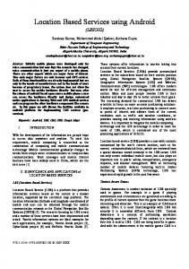
Fig. 4. Real power loss in a 33 bus radial distribution system. (DGs kind 1)
In Fig. 4, the results on the optimization function define in the total real power loss of 33 bus radial distribution system. VI.
CONCLUSION
In this paper, GA is proposed for optimal multi-distributed generation location and size .Test results indicate that the GA algorithm is efficiently finding the optimal multi- distributed generation, compared to APSO, PSO and repetitive load flows, kind 4 DG is the best choice for voltage improvement because it can supply real power and reactive power.
From the results presented in Tables, they can observe that Genetic Algorithm (GA) is effective for optimal multiple DG placement, capacity and number. Also DGs capacity calculations of GA are less than the results of [18], [15], [19]. Table VI shows the methods which are compared, minimum bus voltage magnitude in 33 bus distribution. Voltage base of these systems is 12.66 k V and 10 MVA for MVA base.
REFERENCES [1] [2]
617
T. Ackermann, G. Anderson, and L.S. Soder, “Distributed eneration: a definition”, Electric Power Systems Research, Vol. 57 (3), pp. 195–204, 2001. N. Jenkins, R. Allan, P. Crossley, D. Kirschen and G.Strbac, “Embedded generation”, The institution of electrical engineers, London, 2000, 1st edition,
[3] [4] [5] [6] [7]
[8]
[9]
W. El-Khattam, M. M. A. Salama, "Distributed generation technologies definitions and benefits", Electric Power Systems Research, Vol 71, 2004, pp 119-128., Daly, P.A.; Morrison, J; "Understanding the Potential Benefits of Distributed Generation on Power Delivery Systems" IEEE Power Engineering Society Summer Meeting pp. A2-1/A2-13. S. Greene, I. Dobson, and F. L. Alvarado, "Contingency Ranking for Voltage Collapse via Sensitivities from a Single Nose Curve," presented at IEEE/PES 1997 Summer Meeting, July 1997. R. Christie, UW Power System Test Case Archive, Available: http://www.ee.washington.edu/research/pstca/. Haesen, M.Espinoza,B.Pluymers,I.Goethal,V.Thongh,J. Driesen,R.Belman,and B.de Moor,"Optimal placement and siz-DG ing of distributed generator units using genetic optimization algorithms,"Electrical Power Quality and Utilisation Journal ,vol.11, no.1 2005. M.G.Ippolito,G.Morana,E.R.Sanseverino,and F.Vuinovich, "Risk based optimization for strategical planning of electrical dis- tribution systems with dispersed generation,"IEEE Bologna Power Tech Conference Proceedings,Bologna ,vol.1,p.7,2003. K.Kyu-Ho,L.Yu-Jeong,R.Sang-Bong,L.Sang-Kuen,and Y. SeokKu,"Dispersed generator placement using fuzzy-GA in dis- Constant tribution systems,"IEEE Power Engineering Society Summer Meeting,Chicago,IL,USA ,vol.3,pp.1148-1153,2002.
[10]
M.Gandomkar,M.Vakilian,and M.Ehsan,"A Genetic-Based Tabu Search Algorithm for Optimal DG Allocation in Distribution Networks,"Electric Power Components and Systems ,vol.33,pp. 13511362,Dec.2005. [11] M.F.AlHajri,M.R.AlRashidi,and M.E.El-Hawary,"Hybrid Particle Swarm Optimization Approach for Optimal Distribution Generation Sizing and Allocation in Distribution Systems,"20th Canadian Conference on Electrical and Computer Engineering, BC,Canada ,pp.1290-1293,2007. [12] A. P. Agalgaonkar, S. V. Kulkarni, S. A. Khaparde, and S. A. Soman,”Placement and Penetration of Distributed Generation under Standard Market Design,” International Journal of Emerging Electric Power Systems, Vol. 1 [2004], Iss. 1, Art. 1004. [13] C. L. Masters, "Voltage rise: the big issue when connecting embedded generation to long 11kV overhead lines," Power Engineering Journal, Feb. 2002, vol. 16, no. 1, pp. 5-12. [14] P. N. Vovos and J. W. Bialek, “Direct incorporation of fault level constraints in optimal power flow as a tool for network capacity analysis,”,IEEE Trans. Pwr. Sys., 2005, Vol. 20, No. 4, pp. 2125-2134. [15] W. Prommee and W. Ongsakul, “Optimal multi-Distribbuted generation placement by Adaptive weight particle swarm optimization, ”International Conference on Control, Automation and Systems , Oct 2008. [16] M.E.Baran, F.F .Wu, "Optimal Sizing of capacitor placed on radial distribution systems",IEEE Transaction on Power Delivery, vol.4, num. 1, pp. 735-743,1989. [17] M.E.Baran, F.F .Wu, "Optimal Sizing of capacitor placed on radial distribution systems",IEEE Transaction on Power Delivery, vol.4, num. 1 pp., 735-743,1989. [18] A.Rost,B.Venkatesh,C.P.Diduch,”Distribution System with Distributed Generation Load Floaw,”in large engineering systems conference on power engineering,2006,pp.55-60. [19] W.Kuersuk and W.Ongsakul, “Optimal placement of Distributed Generation using particle swarm optimization”, , AustralianUniversities Power Engineering Conference 2006 (AUPEC 06) , Dec.2006.
618