Interactive Learning of Structural Shape Descriptions from Automatically Generated Near-miss Examples Tracy Hammond MIT CSAIL
Randall Davis MIT CSAIL
32 Vassar St., 32-239 Cambridge, MA 02139
32 Vassar St., 32-237 Cambridge, MA 02139
[email protected]
[email protected]
ABSTRACT Sketch interfaces provide more natural interaction than the traditional mouse and palette tool, but can be time consuming to build if they have to be built anew for each new domain. A shape description language, such as the LADDER language we created, can significantly reduce the time necessary to create a sketch interface by enabling automatic generation of the interface from a domain description. However, structural shape descriptions, whether written by users or created automatically by the computer, are frequently over- or under- constrained. We present a technique to debug over- and under-constrained shapes using a novel form of active learning that generates its own suspected near-miss examples. Using this technique we implemented a graphical debugging tool for use by sketch interface developers. Categories and Subject Descriptors: I.2.6 Computing Methodologies, Artificial Intelligence, Learning [Concept learning] I.2.10 Computing Methodologies, Artificial Intelligence, Vision and Scene Understanding [Perceptual reasoning] [Representations, data structures, and transforms] [Shape] D.2.2 Software, Software Engineering, Design Tools and Techniques [User interfaces] I.2.4 Computing Methodologies, Artificial Intelligence, Knowledge Representation Formalisms and Methods [Representations (procedural and rulebased)] [Representation languages] General Terms: Algorithms, Design, Human Factors, Languages Keywords: near-miss, structural description, shape description, ladder, active learning, sketch recognition, user interfaces
1.
INTRODUCTION
Pen-based sketch recognition interfaces are increasingly common and are being built for a variety of domains, including flowcharts, UML class diagrams, and circuit diagrams. These interfaces provide a more natural interaction than traditional mouse and palette tools, but can be quite time consuming to build if they are to handle the intricacies
Permission to make digital or hard copies of all or part of this work for personal or classroom use is granted without fee provided that copies are not made or distributed for profit or commercial advantage and that copies bear this notice and the full citation on the first page. To copy otherwise, to republish, to post on servers or to redistribute to lists, requires prior specific permission and/or a fee. IUI’06, January 29–February 1, 2006, Sydney, Australia. Copyright 2006 ACM 1-59593-287-9/06/0001 ...$5.00.
of each domain. Rather than build a separate recognition system for each domain, our approach is to build a single, domain independent recognition system that can be customized for each domain. In this approach, building a sketch recognition system for a new domain requires only writing a domain description, describing how shapes are drawn, displayed and edited. This description is then transformed for use in the domain independent system. The inspiration for such a framework stems from work in speech recognition and compiler compilers, which have used this approach with some success [11][2][9]. LADDER is a symbolic language for describing how shapes are to be recognized, displayed, and edited in a domain [4]. The language allows developers to provide a structural description of a shape. Because the description, and thus recognition, is based on what the shape looks like rather than how it is drawn, sketchers can draw the shape as they would naturally, using any number, direction, or order of strokes. These shape descriptions can automatically be translated into recognizers, exhibitors, and editors for use in a multi-domain recognition system [5]. As the sketch recognition interface is produced directly from the shape descriptions, we clearly need to be sure that the descriptions contain exactly the geometric relationships that characterize each symbol. Descriptions with too few relations (constraints) will recognize non-examples of the symbol (false positives), while descriptions with too many relations will produce false negatives, not permitting the degree of variation in a symbol‘s appearance that is routinely accepted by people using that graphical language. Despite being designed to be intuitive, LADDER shape descriptions can still be difficult to write. It is much more natural to draw a shape than type a verbal description. While the work in [8] shows that descriptions can be generated automatically from a single example, these are often imperfect, as it is difficult for the computer to infer the intent of the developer. For instance, the developer may draw a square, when intending something as specific as a square or as general as a rectangle or even a quadrilateral. The alternative - creating a description by hand - may be more time-consuming, but the developer can be specific about the shape intended. The developer may also prefer a manual description because she can describe the shape in a way that is intuitive (e.g., matches her mental model of the shape). But manual descriptions may also contain errors. In a user study we asked 30 people to describe shapes using both natural language and a more structured language (similar
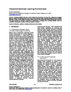
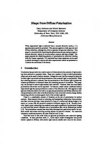
Figure 1: When asked to draw many examples of a particular shape in a user study, users tended to draw the shape in the same fashion repeatedly.
(define shape Rectangle (components (Line top) (Line left) (Line bottom) (Line right)) (constraints (horizontal top) (horizontal bottom) (vertical left) (vertical right) (equalLength left right) (equalLength top bottom)) (equalLength top left) )
(define shape Square (components (Line top) (Line left) (Line bottom) (Line right)) (constraints (horizontal top) (horizontal bottom) (vertical left) (vertical right) (equalLength left right) (equalLength top bottom)) )
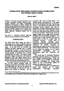
Figure 3: An over-constrained definition for a rectangle. It contains the erroneous constraint (equalLength top left), instead, defining a square.
Figure 2: An under-constrained definition for a square. It does not specify that all four sides need to be the same (which could be rectified by including the constraint equalLength top left).
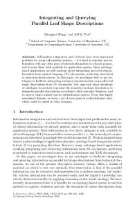
Figure 4: Hand drawn positive example and description.
to LADDER), and found errors in both types of descriptions. Developers may forget a constraint, allowing unintended shapes to be recognized, or they may add too many incorrect or conflicting constraints. As a result, the intended shape may not be recognized. In this paper we describe a visual debugger of shape descriptions using a novel form of active learning [1] that automatically generates its own suspected near-miss examples. The system first asks for a hand-drawn positive example, then aims to learn a structural description that describes the hand drawn shape. To do this, the system generates near-miss shapes to be classified by the developer as positive or negative examples. A near-miss shape is a shape that differs from the initial hand drawn positive example in only one aspect. Because the near-miss differs in only one aspect of the description, only one revision is possible [10], simplifying the learning/debugging process. Most systems that learn from near-miss examples expect the user to provide those examples. A previous method for debugging over-constrained descriptions [6] asked the developer to draw several examples, which were used to refine the description. However, when we performed a user study of 9 people and asked them to describe several examples of a shape, we found that the examples given by people were non-informative: they were typically very similar to the original drawn shape. (Figure 1 gives an example of several arrows drawn by one user.) The problem with the technique described in [6] - which is essentially debugging via userselected test cases – is that the user may never draw the shape in a way that exposes the bug in the description. It is also unlikely that the developer will draw such examples, as we are asking her to illustrate the faults in the description, and if she were aware of such faults, she would simply edit the description.
2.
TYPES OF ERRORS
Errors can be of two types: syntactic and conceptual. Our debugger handles syntactically malformed expressions using
common techniques that are not the focus of this paper. We handle conceptual errors, which can be further sub-divided into two types: an omitted constraint yielding an underconstrained description, or an erroneous constraint producing an over-constrained description. A simple example of an under-constrained description is given in Figure 2, where the definition for a square fails to require all four sides to be the same length (i.e., it is missing (equalLength top left)). An example of an over-constrained shape description is given in Figure 3, where the definition of a rectangle contains the erroneous constraint (equalLength top left). We don’t consider substitution errors (e.g., (vertical top) instead of (horizontal top)) to be an additional error type, rather, we consider them to be the combination of an over-constrained definition (the vertical constraint should be removed) and an under-constrained definition (the horizontal constraint should be added). Redundant constraints (where both are true, but one is not necessary) are not considered errors as they do not affect the correct recognition of the shape.
3.
INITIAL CONDITIONS
Our approach needs a positive hand-drawn example and a description that will correctly recognize that one example (Figure 4). The developer can chose to type the description or have one generated automatically from the hand-drawn example using techniques developed by our group [8]. In either case, descriptions are built from the vocabulary of constraints listed in Appendix A. We start by describing the first steps of the debugging process for user-typed descriptions, because these require initial debugging steps not required for machine-generated descriptions.
3.1
Debugging User-Typed Descriptions
User-typed descriptions are first checked for syntactic validity. Our debugger GUI has a built-in syntax checker, making it easy for users to avoid this simple class of error (see Figure 5). Users can type whatever they want, but incorrect syntax is turned red. This gives them some freedom to define constraints using shapes they haven’t yet added
Figure 6: A screen shot of the GUI used to remove false constraints from a hand typed description to match the drawn example.
Figure 5: A screen shot of the GUI used to enter in typed descriptions of a shape. The GUI automatically checks and controls for correct syntax. to the domain list, but plan to later. It tells them that what they have typed is incorrect, but tries not to interfere with their actions in any way (which would be constricting and annoying). To further aid the developer, the GUI has an auto-complete drop-down box for the component types and constraint names. Once components are entered, those components are automatically added to the list of possible arguments for each constraint. When a constraint is chosen, the number of arguments available for entry automatically changes to reflect the number of arguments for that constraint. Also each argument drop-down box has a dynamically changing list that reflects the possible shapes that are of the appropriate type (e.g., the argument drop-down box for the vertical constraint only lists the accessible lines). This helps to ensure that the user types a syntactically valid shape description. We begin checking the description for conceptual errors by generating a recognizer from the description (using techniques from [5]). If this (known to be correct) example is not recognized, the description must be over-constrained and we start correcting it. The first step is to find a good match between the typed description and the drawn shape, i.e., a set of bindings that associates variables in the description with geometric objects in the drawn shape. The system does this by generating all possible variable assignments and evaluating the constraints in the description for each such set of bindings. (For any given shape and its description, there are many ways that the variable names of the components can be assigned. For example, the arrow described in Figure 7 has 48 possible variable assignments.1 ) The system then chooses the variable assignment with the fewest failed constraints, applying 1 The three variables, shaft, head1, head2, can be assigned to the three drawn lines (using combinatorics) in P (3, 3) = 3∗2∗1 = 6 different ways. Each of the lines can have its two endpoints assigned in 2 ways (23 ), giving the total possible
Occham’s razor on the assumption that the description is mostly correct . The system displays the subcomponents of the failed constraints in red and asks the developer if the indicated failed constraints could be removed to correct the description. If there are several variable assignments containing the minimum number of failed constraints, the system chooses all of them and displays the collection of failed constraints one at a time. A screen shot of this process is shown in Figure 6. The user is required to remove enough constraints to permit their description to recognize the initial hand-drawn shape. This ensures that we start with a positive (handdrawn) example, and a description capable of recognizing it.
3.2
Automatically Generating a Description
If the initial description is generated by the system, it is guaranteed to recognize the hand-drawn example, because we generate descriptions from a list of all of the constraints true of the hand-drawn example. This description is (trivially) guaranteed to recognize the hand-drawn example, but not trivial to create: the list of all true constraints is typically quite long, containing as many as several thousand constraints. In response we have developed an extended set of heuristics (see Appendix B) for pruning this list to keep it both smaller and focused on constraints likely to capture the important geometric properties of the shape.
3.3
The Initial Description
The important point now is that whether we start with a user-typed description or one generated by the system, at this point we now have a description that is known to recognize the hand-drawn positive example. Hence the description is known not to be over-constrained with respect to the single example we have seen so far.
4.
OVER-CONSTRAINED DESCRIPTIONS
The challenge we now face, however, is that while the initial description may recognize the initial hand-drawn exnumber of assignment to be P (3, 3) ∗ 23 = 48. (Notice that this number grows quickly as the four lines of a rectangle can be assigned in P (4, 4) ∗ 24 = 384 possible ways.)
ample, both of them may be overconstrained compared to the actual concept for the shape. This occurs if the initial example drawn by the user is too specific. The arrow in Figure 2, for example, happens to have two perpendicular lines at its head; it is a positive example of an arrow, but overconstrained in the sense that a figure without a perpendicular head is still an arrow. Hand-drawn examples will almost always be over constrained because the sketcher is required to make arbitrary choices. Even if the sketcher had drawn an arrow with a non-perpendicular head, the initial handdrawn example may still be over constrained as an acute (or obtuse) constraint would now be generated instead.
4.1
Constraint Candidate List
Earlier we indicated that we generate the complete list of constraints true of the initial sketch. This list is saved and used as the initial value for a list we call the constraint candidate list. Each time a positive example shape is encountered, we remove from the constraint candidate list any constraints not true of the new positive example (any constraint not true of a positive example cannot be true of the concept). We also generate a list of constraints known to be part of the correct description and lists of candidates that might be part of the correct description. We generate a list of constraints known to be part of the correct description by examining negative examples: Each time a negative example shape is encountered, we construct a list of the constraints that are in the constraint candidate list, but are not true of the negative example shape. We know for certain that at least one constraint in this list is part of the correct description, because it correctly classifies the new example as negative. If this list contains only one constraint, we know that that constraint is a required part of the desired description. If, on the other hand, the list contains more than one constraint, that list is added to the collection of candidate constraints that might be part of the correct description.2 Elements of this collection (lists with more than one constraint) may eventually be reduced to one constraint when some of the constraints are removed after a positive example shape.
4.2
Initial Over-constrained Testing
Because it is often the case that shapes can be rotated and scaled, we first rotate and scale the shape and present several examples all at once to the user. In the case of scaling, the developer is asked to indicate the status of each example individually; the individual positive and negative examples are handled as in the previous section. For rotation, the user is permitted only to say whether or not all of the examples are positive. (We currently do this in order to avoid problems with shapes having rotational symmetry.) If the user indicates that all the examples are positive, they are handled in the fashion described in the previous section.
4.3
Testing Other Constraints
2 Lists frequently contain more than one constraint because constraints are interrelated in the sense that one constraint cannot be falsified without falsifying another: an example shape in which two lines are constrained not to meet, for instance, is necessarily also an example in which those two lines are not connected.
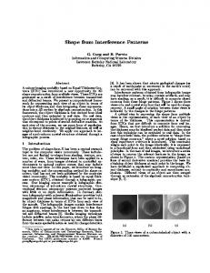
(define shape Arrow (components (Line shaft) (Line head1) (Line head2)) (constraints (coincident head1.p1 shaft.p1) (coincident head2.p1 shaft.p1) (acuteDir head1 shaft) (acuteDir shaft head2) (equalLength head1 head2) (perpendicular head1 head2)))
Figure 7: An over-constrained description of an arrow; it should not contain the constraint (perpendicular head1 head2). The system checks to see whether the description is overconstrained by examining each constraint in turn and generating a suspected near-miss shape to test whether that constraint is necessary. For example, in the description in Figure 7 we test the six listed constraints. 3 Because the topology of a shape is considered to be the most perceptual property of a shape[8], we test all coincident constraints first, presenting several examples all at once to the developer. We modify the constraint candidate list to take into account the positive and negative examples as specified by the developer. A constraint is tested by creating a description in which the constraint is replaced by its negation, then generating a shape that fits this description (using the shape generation technique described below). Figure 8 shows the shapes generated when testing (coincident head1.p1 shaft.p1) and (perpendicular head1 head2). Imagine that the developer indicates that the shape generated by the revised description does not agree with her mental model of an arrow (as in the case of testing the coincident constraint of Figure 8). This shows that the constraint in question is a necessary part of the description because we have a positive example where the constraint is met (the originally hand drawn shape) and a negative example in which the only thing changed is that the constraint is now not met (the generated shape). Imagine on the other hand that the developer indicates that the shape generated by the revised description does agree with her mental model of an arrow (as in the case of testing the perpendicular constraint of Figure 8). Thus, the original description was over-constrained: the constraint is superfluous since we have a positive example in which the constraint is not met.
5.
UNDER-CONSTRAINED DESCRIPTIONS
Once the shape description is known not to be over-constrained, we check whether it is under-constrained, by making a list of possible missing constraints. As the list of possible missing constraints can be very large, we generate it by the same filtering process used in Section 3.2 and described in Appendix B, with several additional filters: The system removes constraints related to the constraints already listed in the description by removing all constraints that already exist in the description, removing constraints that are more general than those that exist in the description, and removing constraints that follow transitively from those in the descrip3 It is possible that a single constraint, when made false, produces a set of inconsistent constraints. In this case, we remove a related constraint (which is defined to be a constraint in the same group - as defined in Section B.8 - sharing an argument) and retest.
5.1
Figure 8: Near-miss examples testing whether description is over- constrained.
Figure 9: Hierarchical examination of the contains constraint.
tion. (This process uses the same code and rules for eliminating constraints as in Appendix B.) As a consequence of the limit imposed by the filtering process in Appendix B, we are left with n2 new constraints to test for possible accidental exclusion. We test each of those n2 constraints to determine whether it is missing from the description by adding its negation to the description (e.g., NOT (horizontal shaft)), then generating a shape based on this description. Figure 10 shows two generated possible near-miss examples testing constraints (horizontal shaft) and (longer shaft head1). Imagine that the developer indicates that the non-horizontal example in Figure 10 agrees with her mental model of an arrow. Because we have a positive example of an arrow with the constraint met (the original hand drawn shape) and not met (the generated shape), we know the constraint should not be included (i.e., it was an accident that the original arrow happened to be drawn horizontal). However, imagine that the developer indicates that not longer example in Figure 10 is not an arrow. In this case we have two examples with identical descriptions except for the longer constraint; the (hand-drawn) shape in which the constraint is met is a positive example, and the (generated) shape in which the constraint is not met is a negative example. This indicates that the constraint is necessary to the concept of the shape.
Generating Shapes
As essential part of the process above is the ability to show the user an example of a shape that meets the revised set of constraints. Satisfying this new list of constraints will require modifying the current location, size, or orientation of the components in the original, hand-drawn example. Because the positions of the shape’s components, its properties, and its constraints are all interrelated, we need to generate and solve algebraic equations demonstrating these relations. To generate a shape we first convert each shape’s components, properties (such as width, height, area), and constraints into a set of algebraic equations. These equations are then solved to find a mathematical solution representing a shape that satisfies the description. When displaying the generated shape, we want each constraint in the description we are testing to be perceptually obvious. Therefore, for each constraint we have hard coded some additional thresholds that must be true. For instance, when generating a shape in which two lines should not have equal length, we require that one shape must be 1.5 times the length of the other. We translate each shape, its components, and its properties using the schema listed below. This produces a set of equations describing the object. For example, one equation produced is arrow.area == arrow.width * arrow.height. • Minimize: To prevent the shape from shifting too much, we minimize the distance from the value in the initial hand drawn example to the final solved value for each component. • Require: To prevent the lines from collapsing to a point, all lines must have a length greater than 20 pixels. • We define the bounding box of a shape (minx, miny, maxx, maxy), so that we can enforce area-related constraints such as equalArea, larger, contains, as follows: – Define shape.minx recursively: if (shape is line): ∗ Require: shape.minx shape.center.x + 20) (We add an additional 20 to ensure the shape appears visually to not have the same ’x’ value.)
Finally, we use the NMinimize function in Mathematica, which finds constrained global optima, to find a solution that satisfies all of the equations above. We now have new positions for each of the shape’s components which satisfy the constraints in the description. The system will then display the shape with its new positions to the developer for her to label as either a positive or negative example. The NMinimize function works faster with fewer variables. To speed up the NMinimize function we remove as many variables as possible. We first remove unreferenced variables. For example: if the equalArea or larger constraint is not used, the height, width, and area variables are not necessary. We then remove any aliased variables. For example, it is often the case that two variables are defined to be equivalent, such as in the case of the p1.y and p2.y being equal in a horizontal line. In this case we remove one of the variables by replacing all of the occurrences by the others. The NMinimize function has several optimization methods that may be used to solve the equation to minimize. The method that works in the largest amount of cases is the Random Search method. This method is also the slowest. However, the other methods require initial values of the points with all of the constraints solved; without these, the system often does not solve the equation to be minimized. To fix this, we move most of the constraints into the minimization part of the equation, making finding initial points which solve the constraints a much simpler problem.4 To ensure that the constraints in the minimization problem are given higher priority we modify our minimization function just as we would a utility function. We give those required constraints a weight of 1000 and optimal constraints a weight of 1, ensuring that the system first tries to solve the necessary constraints before solving the unnecessary ones.5 Sometimes Mathematica either reports ‘Failed’ or reports an extremely high error when trying to solve the constraints. This can occur either because the constraints listed combine to form an impossible shape or because the list of constraints was too complicated for mathematica to solve. Because we can not tell the difference between these two causes, we skip shape generation for this description and move on to the next near-miss example.
6.
SUMMARY
The debugging process is an attempt to create a correct structural description of a shape. We start with a positive hand drawn example. Then either we generate or have a developer enter an initial description of the shape. If necessary, the initial description is modified to make sure it does recognize the hand drawn example. We then test if the description is over-constrained, by making the constraints negative one by one and generating a near-miss shape that tests the suspected superfluous constraint. Similarly, we then test 4 A constraint equation A == B can be translated into a minimization problem by translating it to (A − B)2 . 5 For example a minimization function of 1000(A − B)2 + (C − D)2 places much more effort on making A == B than on making C == D.
if the constraint is under-constrained, by adding a possibly missing constraint in its negative form one-by one and generating a near-miss shape that tests the suspected missing constraint. Throughout this process the developer is being shown these generated shapes and being asked if the example is a positive or negative example. After each response, the description is modified, either with constraints being removed after a positive example was produced, or with constraints being added (or kept) after a negative example was produced. At the end of this process we have a correct shape description that contains no unnecessary constraints and is not missing any required constraints.
7. 7.1
RELATED WORK Multi-Domain Recognition System Debugging
Long [7] has created a multi-domain recognition system in which the developer can specify the shapes to be recognized in a domain by drawing them. The system helps the developer debug shapes by letting her know which shapes are similar and may be confused with others, causing recognition problems. This work is solving a different problem, focusing on ambiguity in the graphical vocabulary, suggesting that certain shapes be drawn differently, as opposed to our system which assumes each shape is drawn as the user intended and attempts to learn what this intention is. [3] has created a multi-domain recognition system, but has no methods for debugging the shapes specified within them.
7.2
Learning from Near-Miss Examples
Winston developed a method for learning structural descriptions from examples [10]. He argues that the ideal training sequence is one where each example is a near-miss. His work supposes that a human teacher supplies the system with appropriate near-misses. However, as mentioned earlier, we have found users to be unable to produce a sufficient range of near-miss shapes that would make evident missing or superfluous constraints. As suggested above, this is a generic phenomenon: whether debugging code or geometric descriptions, good test cases are difficult to generate. To overcome this problem we have the system itself provide the examples that help refine its model. Our work applies this framework to the field of sketch recognition, and we can then recognize shapes based on the learned structural description.
8.
LIMITATIONS AND FUTURE WORK
Our method is limited to describing shapes using constraints in our language (LADDER). Although the system can negate constraints to generate near-misses, it does not generate disjunctive or negation constraints. We are in the process of looking at the data from 45 users who have been asked to describe shapes both in the language and in natural text to determine what constraints are commonly forgotten. We hope we can use this information to greatly reduce the number of missing constraints for which to test, enabling us to include missing negation constraints and disjunctive constraints of a limited order. We have so far tested our technique on shapes composed solely of lines and circles. We plan to add curves and arcs in the near future. At this point we are uncertain of the difficulties that incorporating arcs and curves might cause.
9.
CONCLUSION
equal, greaterThan, greaterThanEqual These constraints compare properties of many different types, so we don’t have any intuition on how to vary them. (We generate constraints comparing properties using property specific constraints such as equalAngle, equalArea, equalLength.)
Sketch interfaces can be generated automatically from shape descriptions, greatly reducing the amount of time necessary to create a sketch based UI. However, creating correct shape descriptions is difficult. To address this problem, we have created a graphical debugging tool for interface developers that corrects over- and under-constrained shape descriptions. The tool learns structural descriptions through active learning by presenting the user automatically generated suspected near-miss examples to refine the description.
negation constraints Negation constraints are omitted because they would greatly increase the number of constraints to test for, as any particular shape has a far greater number of negative constraints than positive constraints. disjunctive constraints Disjunctive constraints are omitted because they would exponentially increase the number of constraints to test for.
Acknowledgments The authors would like to thank Aaron Adler, Metin Sezgin, Mike Oltmans, Jacob Eisenstein, and Sonya Cates for their comments on the ideas in this paper, and David Craft for his analytic geometry skills. This work was supported in part by the MIT/Microsoft iCampus Project.
APPENDIX A. CONSTRAINT VOCABULARY
composite constraints Composite constraints represent consolidations of other constraints. (After the final description is created, we simplify the description using composite constraints.) 2: Label: The system first assigns a labeling to the each of the components in the drawn shape. The system uses a simple labeling process combining the type of the shape and a unique number (e.g., line1, line2).
This section lists the constraints available to describe shape structure. In our approach, signal error in a hand-drawn shape should be handled by the shape recognizer. We accomplish this by giving each constraint its own error tolerance. Because the error tolerances are constraint specific, we have chosen to include constraints which are otherwise redundant. For instance, we included equalLength line1 line2 so we could specify an appropriate error tolerance rather than just using equal line1.length line2.length.
3: List components: The system then creates a list of all of the components that are accessible within one layer of indirection (e.g., line1, line1.p1, line1.center, line1.p2, line1.boundingBox, line1.stroke, line2, etc.) We do this because we want the system to generate constraints using hierarchical shape properties. For example, if we want to describe the shape in Figure 9 (an arrow contained in a box), then the system will also generate constraints pertaining to the subcomponents of the arrow (e.g., in Figure 9, the listed constraints include the fact that the box also contains the arrow’s shaft).
A.1
4: Find True Constraints: We then list all of the unary and relational constraints by testing each of the constraints in LADDER on all possible combinations of shape components in the list produced by step 2.
Orientation Dependent Constraints
The orientation dependent constraints include horizontal, vertical,negSlope, posSlope, above, leftOf, horizAlign, vertAlign, pointsDown, pointsLeft, pointsRight, and pointsUp.
A.2
Orientation Independent Constraints
The orientation independent constraints include: acute, acuteDir, acuteMeet, bisects, coincident, collinear, concentric, connects, contains, drawOrder, equalAngle, equalArea, equalLength, intersects, larger, longer, meets, near, obtuse, obtuseDir, obtuseMeet, onOneSide, oppositeSide, parallel, perpendicular, and sameSide.
A.3
Extra Constraints
The vocabulary also includes constraints to enable developers to describe orientation independent shapes using orientation dependent constraints by adding the constraint isRotatable. The vocabulary also includes equal, greaterThan, and greaterThanEqual, allowing the developer to compare any two numeric properties of a shape (e.g., stating that the height is greater than the width). or and not constraint modifiers are also present to allow the developer to describe more complicated constraints.
A.4
5: Remove Nonsensical True Constraints: There are a number of constraints that may be true but that provide no intrinsic value, such as tautological constraints. These constraints are not generated when finding the list of true constraints in step 3. Before this stage, virtually all shapes with three or more lines in them have over 1000 true constraints. After this initial processing, most shapes consisting of three lines have around 200 constraints. For example, after this obvious reduction, an arrow has 216, and a shape consisting of three vertically aligned equal-length parallel vertical lines has 187. To give an example of some of the rules used: • A shape should not be listed as concentric, coincident, meeting, connected, or intersecting with itself. • The center and the two endpoints of a line should not be listed as collinear. • Even though the contains constraint examines the bounding-box of a shape, neither a line nor a point can contain an item (even a point). • A shape should not be listed as larger than a point.
Composite Constraints
• A line should not be listed as larger than another line. (The constraint longer is to be used instead for lines, as larger compares the bounding boxes of two shapes and longer compares the lengths of two lines.)
The vocabulary also contains a number of constraints that can be composed from other constraints. We include these constraints to simplify descriptions and to make them more readable. They include: smaller, below, rightOf, aboveLeft, aboveRight, belowLeft, belowRight, centeredAbove, centeredBelow, centeredLeft, centeredRight, centeredIn, lessThan, lessThanEqual.
B.
• A shape and a subpart of this shape should not be listed as being on the same side of a line. 6: Remove Duplicate Constraints: Several of the constraints are redundant, or provide no additional information, when taking into account the other constraints. These constraints are removed from the list of true constraints. After this reduction, an arrow still has 170 constraints, but a shape
HEURISTICS FOR PRUNING CONSTRAINTS
1: Constraints not generated A variety of constraints are kept off the list, for the reasons indicated:
consisting of three vertically aligned equal-length parallel vertical lines has been reduced to 53 true constraints. To give an example of some of the rules used: • If a line is listed as vertical, then we remove the constraints stating that any of the line’s subparts are above one another or are horizontally aligned (share the same x value). Likewise for horizontal. • If one shape is above another, then we do not list that subparts of those shapes are above each other (e.g., if line1 is above line2, we don’t list if line1.p1 is above line2). Likewise for the following constraints: left of, horizontally aligned, vertically aligned, on the same side of a line, or on the opposite side of a line.
10: Simplify: The system removes certain constraints that are less important visually, including drawn before and on one side. The system also remove constraints that refer to subparts of shapes, with the exception of coincident and collinear. 11: Select Constraints: We now select a number of initial constraints as our first guess. We limit the number of constraints to n2 , where n is the number of primitive components in our drawn example (e.g., an arrow has three lines, and thus we would choose 9 initial constraints). We use the following selection rules. 1. We first add the constraints with the stars in each of the groups listed above. 2. If there are too many constraints, we find the group with the largest number chosen from it, and remove the bottom one, continuing until there is an appropriate number of constraints.
• We remove any collinear constraints in which all of the points are on a single line when taking into account coincident constraints (e.g., if line1.p1 is coincident with line2.p2, then we will remove the constraint coincident line2.p2 line1.center line1.p2).
3. If there are too few constraints, we pick the group with the fewest chosen constraints and select the next constraint on the list. We continue until there is an appropriate number of constraints.
7: Remove More General Constraints: When a more specific constraint is true, we remove the more general one. • Remove near constraints if points are coincident.
4. If there are still too few constraints, we add subpart constraints that were removed during the simplify step to the groups above (with their original ranking retained). We then continue to add one constraint at a time using the same rules as stated.
• Remove acute and obtuse constraints if obtuse meets or acute meets constraints are true. • Remove constraints that are true because of transitivity (e.g., if line1 and line2 are equal length, and line2 and line3 are of equal length, then we can remove the constraint stating that line1 and line3 are of equal length). This holds for almost all the relational constraints, including equal length, longer, larger, parallel, perpendicular, left of, above, same side, coincident • If coincident, remove similar connected and meets constraints. • If three lines are vertically or horizontally aligned, we remove any collinear constraints between them. 8: Group Constraints: The remaining constraints are then grouped into categories that collect constraints that we believe are interrelated in the sense that testing one often involves testing the others as well. • Unary Orientation Constraints: horizontal*, vertical*, positive slope, negative slope, arc points up, arc points down, arc points right, arc points left • Relational Orientation Dependent Constraints: horizontally aligned*, vertically aligned*, left of, above • Size Constraints: equal length*, longer, larger, equal area • Connectedness Constraints: coincident*, bisects*, connected, meets, acute meets (in two groups), obtuse meets (in two groups), intersects • Relative Angle Constraints: parallel*, perpendicular, acute meets, obtuse meets, acute, obtuse, directed lines acute, directed lines obtuse, equal angle • Location Constraints: concentric*, collinear*, near, same side, opposite side, on one side • Draw Order Constraints: draw order 9: Rank Constraints: The system ranks the constraints. • Order the constraints according to the order listed above (e.g., horizontal line constraints are listed before vertical line constraints). • With the exception of coincident and collinear constraints, move constraints which refer to subparts to the bottom of the list (keeping their relative constraint type ordering).
C.
REFERENCES
[1] D. Cohn, L. Atlas, and R. Ladner. Improving generalization with active learning. In Machine Learning, pages 201–221, 1994. [2] G. Costagliola, G. Tortora, S. Orefice, and D. Lucia. Automatic generation of visual programming environments. In IEEE Computer, pages 56–65, 1995. [3] M. D. Gross. The electronic cocktail napkin - a computational environment for working with design diagrams. Design Studies, 17:53–69, 1996. [4] T. Hammond and R. Davis. LADDER: A language to describe drawing, display, and editing in sketch recognition. Proceedings of the 2003 Internaltional Joint Conference on Artificial Intelligence (IJCAI), 2003. [5] T. Hammond and R. Davis. Automatically transforming symbolic shape descriptions for use in sketch recognition. Proceedings of the Nineteenth National Conference on Artificial Intelligence (AAAI-04), pages 450–456, 2004. [6] T. Hammond and R. Davis. Shady: A shape description debugger for use in sketch recognition. AAAI Fall Symposium on Making Pen-Based Interaction Intelligent and Natural, 2004. [7] A. C. Long. Quill: a Gesture Design Tool for Pen-based User Interfaces. Eecs department, computer science division, U.C. Berkeley, Berkeley, California, December 2001. [8] O. Veselova and R. Davis. Perceptually based learning of shape descriptions. Proceedings of the Nineteenth National Conference on Artificial Intelligence (AAAI-04), pages 482–487, 2004. [9] VoiceXML Forum, http://www.voicexml.org/specs/VoiceXML-100.pdf. Voice eXtensible Markup Language, 1.00 edition, March 07 2000. [10] P. H. Winston. Learning structural description from examples. Psychology of Computer Vision, 1975. [11] Zue and Glass. Conversational interfaces: Advances and challenges. Proc IEEE, pages 1166–1180, 2000.