SEGMENTED SHAPE DESCRIPTIONS FROM 3-VIEW STEREO* Parag Havaldar and Gtrard Medioni Institute of Robotics and Intelligent Systems University of Southern California Los Angeles, California 90089-0273
[email protected],
[email protected]
Abstract: We address the recovery of segmented, 3 - 0 descriptions of an object from intensity images. We use three views of an objectfrom slightly different viewpoints as our input. For each image we extract a hierarchy of groups based on proximity, parallelism and symmetry in a robust manner. The groups in the three images are matched by computing the epipolar geometry. For each set of matched groupsfrom the three images, we then label the contours of the groups as “true” or “limb” edges. Using the information about groups, the label associated with their contours and projective properties of subclasses of Generalized Cylinders, we infer the 3D structure of these groups. The proposed method not only allows robust shape recovery but also produces segmented parts. Our approach can also deal with groups generated as a result of texture or shadows on the object. Wepresent results on real images of moderately complex objects. Key Words: Shape description, Grouping, Stereo, Edge Labeling, Generalized Cylinders.
1
Introduction
Inference and description of the 3-D shape of objects from one or very few intensity images is an important and certainly a challenging problem in computer vision. Such descriptions provide compact representations which can be used to recognize objects, manipulate them, navigate around them and learn new objects. In this paper we address the problem of recovering the shape of an object from three intensity views taken from close viewpoints, and derive volumetric, segmented (or part-based) descriptions in the presence of noise, texture, shadows. We propose to obtain such descriptions by: Grouping: In each image we extract groups by detecting parallel and skew symmetries. These groups are extracted hierarchically to enable robust performance in the presence of noise. Matching: The groups detected in each image are matched. These correspondences are established by using the epipolar geometry between all pairs of images. Labelling: The contours of matched groups in the three images are labelled as “true” or “limb” edges. This labelling provides information about the shape of the underlying
* This research was supported in part by the Advanced Research Projects Agency of the Department of Defense and was monitored by the Air Force office of Scientific Research underGrant No F4%20-93-1-0620.The United States Government is authorized to reproduce and distribute reprints for governmental purposes notwithstanding any copyright notation hereon.
surface. 3 - 0 Inference: The groups whose contours are labelled as limb are hypothesized to come from smooth GCs, while the groups whose contours are labelled as true edges are hypothesized as coming from surfaces. We start by motivating our approach in the light of existing theories of object recognition, and review relevant work.
2
Motivation and Previous Work
Humans seem to understand the shape of objects from intensity images with little effort, even if the objects are occluded, novel, rotated in depth or extensively degraded. However, computer vision has made only a small progress in this direction. Here, we address a few issues which have motivated our work. Do we need to infer 3 - 0 descriptions? There are two schools of thought on human perception, one which postulates the storage of specific viewpoints [51 and the other which states the use of viewpoint invariant volumetric primitives [11. We do not see thesetheories as being contradictory. Tasks such as recognition of an object in the scene require rich and stable descriptions. Volumetric descriptions provide such rich descriptions. Manipulation tasks require an understanding of the object’s pose. Predefined poses of the object may be used to help this process. What kinds of volumetric descriptions? To address the complexity of objects, we need to represent them in an manner that makes their interpretation tractable. Representationsof objects in terms of parts reduces such complexity. In the psychology field, Biederman [ 11 has proposed that part-based volumetric representations based on geons, appear to be psychologically plausible. Similar ideas based on Generalized Cylinders (henceforth GCs) have been proposed by Nevatia and Binford [131 in computer vision. We hypothesize that part based volumetric descriptions based on subsets of Generalized Cylinders (GCs) constitute a suitable level of shape abstraction of large classes of complex 3-D objects. Specifically, the subclass of GCs used are those that give rise to perceptual properties such as symmetries and closures in the image. As a result of this representation scheme, however, objects which can be better described by statistical features, for example waves, bushes, cannot be dealt with. How to infer these segmented 3 - 0 descriptions? Deriving descriptions from real images, in a data drivenfashion, poses many problems. Among them are discontinuous boundaries, the presence of texture and shadows, occlu-
102 0-8186-7042-8/95 $4.00 0 1995 IEEE
Authorized licensed use limited to: University of Southern California. Downloaded on November 16, 2009 at 14:19 from IEEE Xplore. Restrictions apply.
sion etc. The description task can be thought of as a bottom up process guided by the expectations obtained from the choice of primitives. In our case, GCs form such primitives which give rise to symmetries in the image. These features are extracted in a hierarchical fashion using grouping. Rich, descriptive features (symmetries, closures) are present at the upper levels of the hierarchy and low level features (lines, curves) appear at the lower levels. The grouping rules used to generate the hierarchy are dictated directly by the representation scheme used. These rules help overcome noise and other image imperfections. Inferring 3-D shape from intensity images has been looked at by few researchers in the past. Mackworth [ 111 and Kanade [9]used gradient space constraints for recovering face orientations of polyhedral objects. Ulupinar and Nevatia [20] have addressed the recovery of a certain class of objects zero Gaussian curvature surfaces (ZGCs), straight axis homogeneous cross section GCs (SHGCs), planar right constant crosssection GCs (PRCGCs). They take as input perfect line drawings without any texture. Ponce [ 141 et a1 have derived projective invariant properties of SHGCs. These methods recover the shape of a specific classes of GCs composed of a single part. Recently, Z e m u g and Nevatia [22] [23] have recovered SHGC and PRCGC based objects made of more than one part from real images. However other GCs e.g. having varying cross-sections, cannot be recovered by their method. They also require that one or both the cross sections of the GC be visible in order to recover the 3-D shape. We don’t make use of such assumptions. Consequently, our approach should deal with a much broader class of GCs. One of the major differences in the above approaches and ours is that the above ones use one image and look for well defmed invariant properties of a specific class of GCs. We use three images and hence are able to go a step further by labelling the contours (as “true” and “limb” edges). As a result, we can say a lot more about the GC shape. Moreover, this reasoning allows us to deal with more complex objects made of many parts in the presence of texture, shadows and can still give a description in the absence of cross-sections. Vaillant and Faugeras [20], Cippola and Blake [3] have used three images and shown how to compute the local structure along the “occluding” or “limb” contour using three images, but do not address the global part-based structure. Other approaches using structure from motion [181 use point based tracking and hence cannot give rich segmented descriptions. Joshi et a1 [8] estimate the shape of smooth objects by combining local silhouettes using a trinocular stereo rig. They use only simple objects (made of one part) and do not address segmentation. In section 3, we give an overview of our approach. Section 4 describes a hierarchical extraction of groups which are projections of the volumetric primitives. Sections 5 illustrates our method of matching and labelling the contours that form these groups. In section 6, we show how these labels are used to infer volumetric GCs. Finally, we present results of our current system in section 7 and give concluding remarks in section 8.
-
3
Overview of our approach
We need to accomplish the description of models in terms of high level, segmented, volumetric parts. We use three inten-
sity views as input. Groups are extracted in all the views and matched using epipolar geometry. Our approach is shown in Figure 1. Three images enables labelling of edges (true or limb)[3][20] which form the groups. This label suggests the shape of the underlying primitive. It should also be mentioned that since the objective is to acquire descriptions of the shape of the object, the images of the objects are in a controlled environment without background clutter. Using three images has the following advantages: Labelling contours requires at least threeimages [20] [3] and this provides useful information for the shape inference. Salient groups, i.e. groups formed because of contours of a part and/or texture on the part come up in the different viewpoints. By selecting groups present in all the images, we are able to perform a better segmentation than by using grouping criteria in only one image. Groups due to texture, should be consistent with the shape of the hypothesized underlying surface in 3-D. This is shown in section 7. Also reasoning at the volume and surface level in 3D helps perform a stronger segmentation.
Matching grou s of three images using epi[alar geometry
4 Label contours of matched groups
A
I
L I 3-D volumetric esc i tions in terms of pad?
Figure 1 Description of approach
4
Extraction of groups
The volumetric primitives which are to be recovered are a subset of GCs which give rise to perceptual groups such as symmetries in the image. This section briefly describes the robust extraction of such groups from the image in the presence of noise, texture, imperfect boundaries etc. For a detailed description, implementation and analysis see 161, [71.
4.1 Preprocessing First edges in the image are detected using the Canny edge
103
Authorized licensed use limited to: University of Southern California. Downloaded on November 16, 2009 at 14:19 from IEEE Xplore. Restrictions apply.
detectorl21. The resulting edgels are further linked into curves. Curves are then linearly approximated with a set of line fitting tolerances to get a robust representation in terms of segments. In Figure 2 an example scene and the detected edges is shown. Proximity indexing is then used to efficiently extract the groups.The hierarchy we extract is shown in Figure 3.
A symmetry is defined as a one-to-one mapping between the points of two curves, with the symmetry axis defined as the locus of the mid-point of the straight lines joining a point on one curve to its image in the other [ 121. Ulupinar and Nevatia have proposed two specific symmetries, namely skewed and parallel symmetries [19]. which we use here. Parallel Symmetries: Parallel symmetries are retrieved by finding proximate parallels. We do not use super segments, because we would depend on the cardinality of the super segments. By using the parallels as the building blocks, we can use proximity indexing to find parallels which share the same vertices. Examples are shown in Figure 4(1eft) --.
\&
3
Figure 2 “Pokey” Image and detected edges
FJ
Preprocessin Stage
7
edge detection
curves linear approximation I
Grouping Stage
parallelism parallels
super segments
proximHy skewed symmetries
angles
X%?,Clty
parallel symmetries
I high leve groups
Figure 3 Grouping Hierarchy
4.2 Super Segments In a real edge image, boundaries are rarely continuous. As described in [ 171. connected linear segments form chains of adjacent segments. The segment chains provide the super segments by grouping a fixed number of ad-jacent segments. We generate super segments of cardinality two to six.
4.3 Parallels A parallel consists of two linear segments J I and 5 2 having approximately the same orientation. We require that the two segments overlap, which means that the normal projection of .\I on .s2, or the normal projection of s2 on .sf not be empty. Furthermore, we do not want the aspect ratio of the parallel to reflect elongation, with ur(p] = (length(5 I ) + length(s2))ldistance(.sl s z ) . We require u r ( p ) > 0.5. Parallels are extracted from the segments using proximity indexing.
4.4
Symmetries
Skewed Symmetries: Skew symmetry was first proposed by Kanade 191 and used in the analysis of scenes of polyhedral objects. Unlike [ IO][ 161. we compute skew symmetries between super segments. An example is shown in Figure 4(right). The entire hierarchy on figure 2 takes about 13 seconds to compute for the image shown. 14 curves were detected which were approximated by two fitting tolerances. These gave rise to 67 segments and 268 supersegments, I39 parallels were detected from the segments. These further gave rise to 24 symmetries (parallels and skew). Perceptually similar features were then grouped as in our previous work 161. 171 to generate 13 high level groups. The time complexities of proximity indexing are O(n)for encoding and O(n’Ir l o g ( n l r ) )when the entries are unsorted. Here n is the number of features and r is bucket size. A detailed explanation of these complexities is available in [6].
5
Matching and Labelling Groups
As mentioned in the beginning of section 3, we need to reason about the type of contours ( r e d or limb) which form the
group. At least three images are required for this purpose [ 3 ] [20]. This will ultimately enable the reconstruction of the underlying volumetric primitive. Given three images we can extract, for each image, a hierarchy of groups as described above. In order to label edges of the groups extracted in the three images. correspondences must first be established between the groups and their contours in three images. The matching and labelling of groups is discussed in the next two subsections
5.1 Matching Groups Groups extracted in different images are matched using epipolar geometry (derived from the fundamental matrix F ) . Therefore the fundamental matrix between all the sets of two images. We use the method proposed by L)eriche* et ul [ 101 to compute the fundamental matrix F . For a point m in an image, the corresponding point lies on the epipolar line given by mF
VI*‘
= 0 . Correspondences are obtained by starting with
1\13
Authorized licensed use limited to: University of Southern California. Downloaded on November 16, 2009 at 14:19 from IEEE Xplore. Restrictions apply.
~
high level features. Such features are distinct, easier to match and give fewer ambiguous matches unlike points or lines. A group (which covers and area) in one image associates a pencil of epipolar limes in the other image along which the matched grouping is expected to lie as shown in Figure 6. For each group in one image all possible group matches are hypothesized in the other image. Although we use high level features to obtain matches, there could be more than one match, because more than one p u p can lie along the epipolar pencil in the other image as shown in Figure 7. The third image is used to verify the hypothesis generated in the first two. i.e. if group- 1 in image- 1 matches group-2 in image-2 and p u p 3 in image-3, then from the epipolar geometry between image3 and image-2, group3 should match group-2. An example of such disambiguation is shown in Figure 8.
Figure 5 Eample of matching group
Figure 6 Example of ambiguous matches.
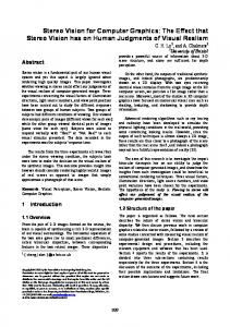
spondences in their images should be incorrect. This property is used to identify limb contours from true edges, which correspond to the projection of the same physical edge (orientation discontinuity or surface marking). Since group-matches between the three images have already been obtained, contour correspondencesof each group in all the three images can be hypothesized. Consider one such set of hypothesized points- m l , m2 and m3. m3 in image-3 is constrained to lie on the epipolar line corresponding to ml in image- 1. Similarly m3 is also constrained to lie along the epipolar line cofiesponding to m2 in image-2. If m l , m2 and m3 are the projections of the same point in 3-D, then the two epipolar lines defined above would intersect at point m3 in image-3, thus indicating that ml ,m2 and m3 are projections of a point lying on a true edge. On the other hand, if these epipolar lines don't meet at m3 but slightly away from m3, then this is a strong indication of a point on a limb edge. The key to distinguishing them as a limb edge is that such epipolar line intersections will be consistently off on the same side of their target point for all hypothesized point matches lying on the limb contour. Since we deal with groups instead of individual points [3] [20], we are able to get a distribution of all the intersecting epipolar lines of the points on the contours of the group. This enables a more robust labelling rather than the use of just a single point. In Figure 10, the distribution of the distance of points of intersection of the epipolar lines from the actual corresponding point is shown for the real and limb edge computations of Figure 9. As mentioned above, it can be seen that in the case of a limb edge the distribution is consistently one sided. It should also be mentioned that while most edges can be labelled with good accuracy, some edges cannot. These are mainly those where the epipolar lines from the other two images are almost parallel and hence the intersection point location is prone to error. This situation is easily detected in which case we do not assign a label to the edge in question.
view 1
U
view-2
epipo/eF of group mb,nci/ Mew-2
U
points of intersection of the m r r e y d i n g epipolar ines
view-3
Figure 7 Example of a correct match using three images
5.2 Labelling edges of a group Once group matches between the three images have been established, the underlying contours of the groups can be labelled as being limb or true edges. We use the ideas similar to the ones described in [3] and [20] to accomplish this as follows: Apparent or Limb edges do not correspond to physical curves on the surface but depend on the viewpoint. Since different points are viewed in different images, the point corre-
Figure 8 Two sets of hypothesizedpoint correspondencesart shown in all the views. View-3 shows the intersectionpoints o the epipolar lines. These intersections are consistent1 off in the case of the limb edge compared to the true &&e.
* We would like to thank,rcstarchersat INRlA for providing us with the software whch enabled efficient computabon of the fundamental mamx F 105
Authorized licensed use limited to: University of Southern California. Downloaded on November 16, 2009 at 14:19 from IEEE Xplore. Restrictions apply.
Number or points
Number or points
,
,w-.mn
Distance of intersecting epi lar lines from the actual location of porn/% third image
two images can be used to achieve this. The disparity is w m puted as the difference in x-coordinates, after projectively transforming the image planes to make their epipolar lines parallel. In Figure 12, the computed 3-D axes for such groups of the horse images are shown. The volume, whose projection gave rise to the groups in the images can be reconstructed by identifying the cross section and sweeping it across the already computed 3-D axis. The sweep function can be obtained from the contours in the image. If the cross-section cannot be identified, then we assume that the cross-section is circular and sweep it along the 3-D axis such that its projection gives rise to the limb boundaries. In Figure 12, the reconstructedvolumetric limbs are shown. .
Figure 9 Distribution of intersecting epipolar lines around a true edge (left) and limb edge (right). I,
d~
.
Trueedges
reconstructed axis and surface of fore-leg
Figure 10 Labelled edges
Figure 11 Reconstructed surfaces of ‘limb’ groups
This proposed method of hypothesizing matches and labelling the underlying contour is performed at all levels of the hierarchy, starting from the highest level. Some of the groups may not show up at the highest level because of noise, occlusion etc. As we go lower down in the hierarchy, we perform the process only for those groups whose contours have not been labelled completely. In Figure 1 1 the labelled contours are shown. Those which do not have any label either did not form any group which matched in all the three images, or the epipolar lines there were almost parallel to the contours and hence prone to high error.
6
Inference of 3-D Primitives
In this section, we attempt to construct 3-D volumetric primitives from the labelled groups. Constructinga volumetric description should also enable us to reason about groups (e.g. due to texture) which are not a result of the structure of the object. Such groups either reinforce or conflict with our hypotheses. The contours comprising the groups may all be ‘limb’ boundaries, or may all be ‘true’ boundaries, or they may be a combination of ‘true’ and ‘limb’ boundaries. Our current implementation is deals with first two.
6.1 Groups whose contours are limb edges Smooth surfaces in 3-D project to this type of group. In order to recover the GC volume, the axis, the cross section and sweep function need to be determined. We make use of quasi invariant properties of straight and curved axis GCs described by Zerroug and Nevatia [21] to reconstruct the volume, namely, the projection of the axis of the GC coincides with the axis of the projection. Therefore, the 3-D-axis of the volumetric part needs to be computed first. Since groups have already been matched in the three images (and also their axes), disparity measurements between two corresponding groups’ axes in
reconstructedaxis and surface of hind-leg
L
Back
Side
Figure 12 Reconstructed surfaces-Back (above) and Side (below) Groups detected in two images were used for reconstruction
6.2 Groups whose contours are true edges Groups generated by surface discontinuities and markings fall into this category. The 3-D primitive which projects onto such a group is not volumetric but is a surface. Inferring volumetric primitives would require reasoning about these surfaces. Hence we first compute 3-D surfaces from these groups. Each group is hypothesized as coming from a surface in 3-D. In this case the 3-D true edges need to be recovered. This is done similar to the 3-D axis recovery described in the section 6.1. For each side or each edge of the group, we compute disparities between the corresponding points using two images. In Figure 13, the 3-D reconstruction of such surfaces are shown. Inferring volumetric primitives requires the recovery of the 3D axis, the cross-section and the scaling function. This level of reasoning and inference has not been implemented yet and is our focus of future research.
106
Authorized licensed use limited to: University of Southern California. Downloaded on November 16, 2009 at 14:19 from IEEE Xplore. Restrictions apply.
7
Results
The 3-D reconstruction for "Pokey" 1s shown in Figure 14. In this case, part of the tail is not reconstructed because the epipolar lines were almost aligned with the contour. Also, since the hind legs did not show up in one of the images, they could not be recovered in the final image. The body's cross section could not be seen and hence could not be recovered. Inference of the cross section and other surfaces needs to be incorporated as explained above. A similar reasoning goes for the cross-section of the face which is not available in all the images. Hence the face is more of a planar surface.
needs mention is the base of the kettle. The limb boundaries in this case could not be recovered because of the corresponding edges were not present in all the images (due to shadow and choice of viewpoint). However, a parallel symmetry is formed between the base of the kettle and the bottom contour of the body. This got labelled as a true edge, resulting in the curved surface shown. A similar reasoning goes for the base of the spout. The spout is partially occluded and has a shadow cast on it. As a result the reconstructed spout 'hangs' in the air and has a smaller lower section than it actual ground truth. Their axes were extended to make one continuous body. Unlike the detergent bottle case, the texture edges on the kettle did not form any
/
I
I ._ -
'!
I
1
1 9 1
d
Three views of 'pokey
-
I
intensity (above) and edges (below)
11
/I@[ L '
Three views of a detergent boftle - intensity (above) and edges (below)
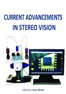
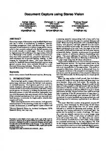
Flgure 73 Reconstructed,segmented 3 - 0 parts of "Pokey' displayed from differentnewpomts In Figure 15 we show another example processed by our current system. Three views of the detergent bottle are shown. which were taken as input. Groups were generated and matched. The resulting reconstructed bottle and the segmented parts are shown. As can be seen, the groups with limb edges generated the body, the lid and the neck. The handle consists of two surfaces because the groups that it gave rise to were labelled as true edges. They are, however, incomplete, because labels could not be determined for the entire contour (see end of section 5.2). The groups due to texture. which also got labelled as true edges, were reconstructed as surfaces in 3-D. As seen from the two different viewpoints with reprojected texture, the surfaces hypothesized by the texture groups are consistent with tLe volumetric primitive generated by limb edges which gave rise to the body. This shows how our method can segment out texture. Figure 16 shows another example. The model views used for this were that of a teapot from three slightly different vieupoints. The resulting segmented volumetric components are shown. The handle consists of two surfaces. Not all the surface of the handle could be recovered for reasons similar to the above example. Another reconstruction shortcoming which
Reconstructed 3-0bottle from different viewpoints
Reconstructed arts Of bottle body. ha"&, lid, neck
The groups formed as result of texture are on the surface of the body
Figure 14 TDetergent Bottle
8
Conclusion and Future Directions
We have demonstrated an approach to recovering segmented, volumetric primitives of an object from three similar intensity images in the presence of noise texture, shadows etc. Thi\
Authorized licensed use limited to: University of Southern California. Downloaded on November 16, 2009 at 14:19 from IEEE Xplore. Restrictions apply.
is achieved by efficiently extracting groups (currently symmetries) from the image. Use of three images enables the matching and labelling of the contours forming these groups as ‘true’ or ‘limb’. With this knowledge of the label and the groups, we are able to reconstruct the type of volumetric primitives and/or surfaces which gave rise to the groups and also segment texture. The encouraging results suggest a promising direction of research. Our current segmented description is not yet mature. Reasoning procedures need to be implemented to go from surfaces bounded by true edges to volumes. Inference mechanisms need to be implemented when not all surfaces are visible. Currently, we deal with groups which have either true edges or limb edges, but groups might give rise to a combination of both and volumetric descriptions should be obtained for such cases. Besides, the reconstructed volumetric primitives by themselves do not give a description of the entire shape. The interconnections of these parts must also be described to get a complete and continuous (as Seen in the images) 3-D model of the object.
Bibliography - - I. Biederman. Recognition-b Com onents: A The0 o Human Image Understanding. aychokgical Review 1 7 8 l Vol. 94, NO 2, 115-147. J. Canny, A Com utational Approach to Edge Detection, IEEE
Transactions on fattem Analvsis and Machine Intelligence, Vol. 8, 1986, ages 679-698. R. Cipoli and A. Blake. Surface Shapefrom the Deformation of Ap arent Contours. Intemational Joumal of Computer Vision,
-
9:$83-112, 1992.
R. Deriche, Z. Zhang, Q.T. Luong, 0. Fau eras. Robust recovery of the epi olar eometry for an uncali%ratedstereo rig. In Proceedine ofthe iuroDean Conference on Computer vision, a es 5674576, vol I, 19994. .! helman and H.H., Bulthoff. Orientation Dependence in !he Recognition of Familiar and Novel Views of 3-0 Objects. Vision Research, 32 ages 2385-2400, 1992. P. Havaldar, Medioni and F. Stein. Perceptual Grouping for Generic Recognition. Intemational Joumal of Computer Vision - to appear P. Havaldar, G. Medioni and F. Stein.Extraction of groups for recognition. Proceedings of the Euro an Conference on Comuter Vision, volume I, a es 251-2$Stolkhoh, 1994. .! Joshi, N. Ahuja and bonce. Structure and Motion Estimation from Dynamic Silhouettes. Technical Report UIUC-BI-AI-
8 -
f
RCV-94-01 T. Kanade. Recovery of the three-dimensional shape o an object rom a single view. Artificial Intelligence, 17:4&-4460.
f
198
.
101 D.J. Krie man and J. Ponce. On Recognizin and Posi!ioning Transactions on curved 3-&)objects from Image Contours. Pattem Anal sis and Machine Intelligence, 11 1 1 D.G. Lowe. 5hree-dimensional object recognition from sin le two-dimensional images, Artificial Intelligence 31, 1987, 3f5-
Eh
7nc J7J.
121 A.K. Mackworth, Inter retin Pictures of Polyhedral Scenes. Artificial Intelligence. 8121-837. 1973. : Nevatia. Using Perceptual Organization to Ex131 R. Mohan and R tract 3 - 0 Structures, IEEE Transactions on Pattem Anal sis and Machine Intellieence. Vol. 11. No. 1 1 . November 198g pages 1121-1139. ‘ R. Nevatia and Th. 0. Binford - “Description and reco nition of curved objects”. In Artificial Intelligence, 8( 1):77-98,%ebmary 1977. J. Ponce, D. Chelberg and W.B. Mann. Invariant Pro erties of Straight Homogeneous Generalized Cylinders and tieir Contours. IEEE Transactions on Pattem Analysis and Machine Intelli ence, 11(9 : 951:966, 1989, Roberts. i Aa c h e PeFephon of %ee Dimensjonal Sol1161 L.
- -
Three views of a teapot - intensity (above) and edges (below)
d
ids.
tical and Electro-optical hformahon Processmg, pages
1 5 9 - 3 7 , 1968.
P. Samt-Marc and G. Medioni. B-spline contour representation and symmetry detection. In First European Conference on Comuter Vision, pages 604-606, Antibes, France, April 1990. Stein. Structural Indexingfor Object Recognition. Ph.D. Thesis, USC IRIS C. Tomasi and T. Kanade. Shape and motion from image streams under orthograph a factorization method. Intemational Joumal of Computer &ion, vol 9, No 2, Nov 1992, pages
6.
137-154.
E Ulupinar and R. Nevatia, Perception of 3 - 0 su aces from 2D contours, In IEEE Transactions on Pattem An ysis and Ma-
Reconstructed teapot from different viewpoints
d
chine Intelligence, a es 3-18, Jan 1993. R. Vaillant and 0.8. Eau eras. Using Extrema1 Boundaries for 3 - 0 Object Modelling. Transacuons on Pattem Anal sis and Machine Intelli ence. Vol 14;2, pages 157-173, Feb l d 2 . M. Zerroug and R. Ifevatia, Quasi-invariant Properties and3-D
&
Sha e Recovery of Non-Straight, Non-Constant Generalized CyJnders. In Proceedings of Computer Vision and Pattern Reco tion, pages 96-103, 1993, New York. and, R. Nevaba, Segmentation and Recove 1231 FZerroug SHGCs om a Single Intensity Image. Proceedmgs of the uroOf pean onference on Computer Vision, pages _ _ 319-340, stolkholm, 1994. 1241 M. Zerr~ueand R. Nevatia, Segmentation and 3 - 0 Recovery of Curved &is Generalized Cylinders from an Intensie Image. In
(?
Reconstructed pads of teapot - body, handle, spout, lid, base
2
Proceedm s of the International Conference on Pattern Recognition, 1964.
Figure 15 Teapot Example
108
Authorized licensed use limited to: University of Southern California. Downloaded on November 16, 2009 at 14:19 from IEEE Xplore. Restrictions apply.