in the neighbourhood, which can in turn recursively spawn new samples. ..... Other directions include rendering with shadows or more sophisticated illumination.
Interactive Sampling and Rendering for Complex and Procedural Geometry Marc Stamminger, George Drettakis iMAGIS / GRAVIR - REVES - INRIA Sophia-Antipolis 2004, route de Lucioles, F-06902, Sophia-Antipolis, France. {Marc.Stamminger|George.Drettakis}@sophia.inria.fr, http://www-sop.inria.fr/reves Abstract. We present a new sampling method for procedural and complex geometries, which allows interactive point-based modeling and rendering of such scenes. For a variety of scenes, object-space point sets can be generated rapidly, resulting in a sufficiently dense sampling of the final image. We present an integrated approach that exploits the simplicity of the point primitive. For procedural objects a hierarchical sampling scheme is presented that adapts sample densities locally according to the projected size in the image. Dynamic procedural objects and interactive user manipulation thus become possible. The same scheme is also applied to on-the-fly generation and rendering of terrains, and enables the use of an efficient occlusion culling algorithm. Furthermore, by using points the system enables interactive rendering and simple modification of complex objects (e.g., trees). For display, hardware-accelerated 3-D point rendering is used, but our sampling method can be used by any other point-rendering approach.
1 Introduction and Motivation The complexity of virtual environments has grown spectacularly over the recent years, with the advent of high performance, but affordable, graphics hardware. The paradox is that the majority of objects in such scenes often covers only a few, or even fractions of, pixels on the screen. The traditional advantage of polygon-based scan-line coherence is thus lost, while resources are wasted by transforming and clipping geometry which is either invisible, or is smaller than a pixel. This has led to the investigation of alternatives to pure polygon-based rendering in recent research. Several researchers have turned to ray-tracing based approaches (e.g., [14, 24]); An interesting recent alternative is pointbased rendering [4, 16, 19], which is actually an old idea revisited [6]. Point based rendering methods represent the scene’s geometry as a set of point samples, that is object space position, surface normal and material data. Usually, the point samples are obtained from images of the scene that include depth and material information, but they are rendered and lit as independent small polygons or oriented disks. It has been shown that such point sample representations are well suited both for fast rendering of extremely complex geometry [19] and for high-quality visualisation [16]. These methods however generate samples as a pre-process, thus restricting their use to static, unmodifiable scenes. In this paper, we focus on points as a primitive well adapted for interactive applications and non-static scenes. We believe that points are particularly well suited for such applications for the following reasons: Objects can be represented at different levels of details very efficiently, by properly choosing point densities (e.g., [19]). When we interactively modify procedural objects, sample recomputation is necessary for all levels of detail, at every
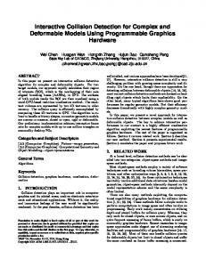
Fig. 1. Examples of our point sample generation algorithm.
frame. Most level of detail techniques create coarse levels bottom-up, resulting in computational expense proportional to the object’s complexity. In contrast, point samples can be generated top-down, so coarse representations are obtained very quickly. In addition, a coarse representation of an object can be refined incrementally, for example for a closer view, by adding new points. If the object does not change, all old samples remain valid. Rendering procedural and dynamic objects requires adaptive refinement in critical regions. With points this can be easily achieved in a straightforward manner by adding additional points locally. Since point representations do not require the maintenance of topological information, object topology can be trivially changed. Examples are CSG models or geometry modifiers such as the wickerwork or holes modifier used in Fig.1. In contrast, the use of meshes (e.g., of triangles), to represent dynamically changing procedural objects or non-standard topologies requires intricate book-keeping when adaptively subdividing, and careful processing to avoid cracks and other artifacts. This leads to complex implementations and numerical robustness problems. Points representing a single object or surface are independent, so they can be generated in parallel, in contrast to polygonal meshes. As we shall see, points also lead to simple solutions for visibility culling, and can take advantage of hardware acceleration more easily than for triangles, which require the use of triangle-strips which are non-trivial to generate adaptively. We present an integrated system which incorporates the above advantages, and can be used for applications such as interactive procedural modelling for design of outdoors or indoors scenes, or VR/game type interactive viewing and manipulation. To achieve sufficiently rapid generation of point samples in this context, we introduce 5 adaptive sampling. Our new scheme allows us to hierarchically generate new samples locally, in the regions they are required, according to the current viewpoint. We apply this approach to procedural models, including displacement maps and terrains. For complex objects such as trees, we use quasi-random sampling to generate points. The continuous level of detail property of points allows smooth frame rate control. Finally, the use of a hierarchical caching mechanism, parallel computation and an direct mapping to graphics hardware vectors, significantly increases the efficiency of rendering. Examples of our approach are shown in Fig. 1.
2 Related work Levoy and Whitted [6], were the first to explicitly investigate the use of points as an alternative to traditional geometry; They treated issues of displacement mapping and texture filtering. In the last few years, there has been significant interest in point-based
approaches. Grossman and Dally [4] generated point representations of objects in a preprocess, and presented efficient ways of rendering them. The Surfels approach [16], concentrates on ways to efficiently render point representations, and presents several reconstruction mechanisms. Points are also used in the Q-splat algorithm [19], whose goal is to render very large polygonal data sets. The emphasis of this work is the compactness and the flexibility of the data structure and consequent rendering quality to allow treatment of enormous databases, and in particular those that do not fit into main memory. A direct ray-tracing algorithm for point-sets has been developed by Schaufler and Wann Jensen [20]. The use of particles for modeling, e.g., [23], is also related to the use of points. The particle systems of Reeves and Blau [18] are in the spirit of our work, however not in an interactive context. In [26], an explicit level of detail mechanism is applied in which leaves become points and then disappear, resulting in effects similar to ours for trees, but from a completely different standpoint. Interactive display using ray-tracing approaches is also related to our work; examples include the Utah interactive ray-tracing environment [14] and the Render Cache [24]. Image-based rendering techniques share several problems with points based methods, in particular for hole filling. Some of the solutions developed, for example layered depth-images e.g., [22, 8] and the work of Max for trees [9] are in a similar vein to those developed for Surfels for example. In what follows, we will be using procedural models, often based on the noise function [15]. We have used or been inspired by several models described in [11, 7]. The procedural and other geometric modifiers we use are inspired by the work of Neyret [12] and Dischler e.g., [2]. The approach of Meyer and Neyret [10] in particular permits interactive viewing of similar kinds of procedural objects; The generation of slices however requires quite sophisticated hole filling techniques. The initial idea of linebased occlusion culling for which we use for terrains can be found in [5]. The Reyes [1] rendering architecture is close in spirit to our approach. Objects are tessellated into polygons, until their size is under some predefined threshold. The major differences are that their system stays in the polygonal world, and the emphasis there is high quality rendering rather than interactivity; the choices and tradeoffs are thus very different from our own. A very recent paper partially covers similar ideas for the rendering of complex static scenes [25], in the context of a walkthrough system.
3
5-Sampling: adaptive point generation
As mentioned in the introduction, procedural objects like displaced surfaces will require adaptive sampling. The 5-sampling scheme is a hierarchical object-space sampling which allows us to efficiently treat displacement mapped objects, procedural geometry modifiers and terrains. We start with an initial set of samples for each object, with each sample corresponding to a region of surface A (“sample area”) on the object (Fig. 2(a)). The union of these regions entirely covers the object. The projection of the region A in image space is A��� A cosα , where α is the angle of the surface normal to the viewing direction, and d2 d is the distance of the surface element to the eye (Fig. 2(a)). If we were to compute the exact projections A � of the sample regions onto the image plane, we would have an image of the object without holes. Since our goal is interactive rendering, we instead project the center of the sample to the image, and draw a simple primitive around it in image space (a hardware accelerated disk in practice). To avoid
A
eye
A
a
d (a)
(b)
(c)
Fig. 2. (a) The basic point sample geometry in world and image space. (b) Object curvature results in denser sampling as we approach silhouettes. Projective foreshortening results in denser image space sampling further in the distance. (c) After displacement, holes appear in the steep parts (left). With adaptive insertion of new samples, these holes are filled (right),
holes, this primitive should have an image space area which is roughly the size of A � . The size of these primitives provides a user-controlled tradeoff between speed and quality. The user defines a threshold Am � in , which is the desired image size of a projected � in is 4, a sample will cover 2x2 pixels on average in sample region. For example if Am � in , fewer samples will be generated, resulting the image. Thus for larger values of Am in faster display. This is similar to the approach used in Q-splat [19], for controlling display speed. Clearly, a uniform sample density in object space does not always result in a uniform density in image space, as illustrated in Fig. 2(b)-(c). Displacement mapping makes this worse. In what follows, we present a sampling scheme which increases sample density where required for such objects. 3.1 The Hierarchical Sampling Scheme When choosing the initial points, we try to capture all essential object features by choosing a sufficiently dense set of points. For certain classes of procedural objects, we can use a priori information about the frequencies used to generate them. If probable undersampling is detected during evaluation of a point, new samples are created locally in the neighbourhood, which can in turn recursively spawn new samples. Appropriate sampling of a displaced surface, for instance, should increase sample density in steep regions. � in To guide the refinement process, we define the undersampling factor F A � Am which is a measure of how well the current set of samples represents the object, given the users choice of sample size Am � in . If F 1 we meet the user define Am� in criterion. If F 1 too many samples were initially created and finally if F 1 more samples are needed, thus spawning additional refinement. We assume that we have an u v parameterisation of the object considered. Initially, we create a uniform grid of points in the parameter domain. The grid step size is h; we can consider u0 h 0 and v0 0 h to be the initial spawning vectors, Fig. 3(a). When denser sampling is required locally, we refine or subdivide single grid points. To refine an initial grid point, four new points are inserted at relative positions:
�
�
�
��� �� � � �� � �
u1
� v � 5�
2u0 5
0
v1
� u � 5 0
� �
2v0 5
(1)
as well as u1 and v1 (see Fig. 3(c)). Thus, after each initial point has been refined, the initial and refined points form a new uniform grid of step size h 5 (Fig. 3(b)). The new grid is spawned by vectors u1
�
3 3
v0
4
v1 u 1
u0 (a)
4
2 p 1
2
p
q
1
(b)
(d)
(c)
(e)
Fig. 3. 5 sampling. (a) initial grid with vectors v0 , u0 (b) once subdivided and rotated grid spanned by vectors v1 , u1 (c) adaptively refined sample set (d) fractal covered by generated samples (e) resolving boundary problems
�
and v1 and it is rotated by an angle of α arctan 1 2 � 26 6o. This refinement procedure can also be applied to the new grid, using offset vectors u2 2u1 5 v1 5, v2 u1 5 2v1 5, u2 and v2 and so forth. The grid at level i i has grid size 5 and a rotation angle of iα. Note that this refinement process can be done locally, resulting in increased sample density where needed (see Fig. 3(c)). All descendants of a single grid point form a fractal, Fig. 3(d), which is very similar to the dragon fractal [21]. The computational effort required for 5 sampling is minimal, since we can precompute vectors ui vi . In order to subdivide u v at level i, we simply insert new points at u v ui , u v vi , u v ui , u v vi . The samples form a forest, with one tree per initial sample, which are “root”, Fig. 3(d). Each node has 5 children, four with an offset according the level in the tree and a self copy. Consider the 2x2 grid shown in Figure 3(d), which has been subdivided globally several times. Some regions, shown in white in the figure, are never reached, due to the fractal like nature of our construction. Our solution is to also examine neighbours during subdivision. When subdividing a point p, we always look at its neighbours; if a neighbour p� lies outside, but one of its children lies inside, we attach it as a child to p, Fig. 3(e). Note that these neighbours do not exist in the initial grid or its subdivisions. Care has to be taken since other neighbours of p may then have the same children attached. For example, 1� and 4� are attached to p� and also to q in Fig. 3(e). The solution is to attach such “boundary children” of p � to a single neighbour of p � . We choose the neighbour which is inside the boundary and is closest to the child being considered. This sampling scheme has nice properties. Due to its uniformity and its lack of randomness new samples are well positioned in between other samples resulting in little overlap. The scheme is purely hierarchical, i.e., every point has exactly one parent in a previous level. Two other schemes with this property are a corresponding 2-subdivision scheme (u0 v0 1 2) or a 9-subdivision scheme ( ui vi 1 3 0 1 3 2 0 0 . The former has a very directional nature: when refining a sample, only one new sample is created, and it is always offset in a certain direction. The latter scheme has a large branching factor of 9.
� �
�
�
�
�
� � �
�
� � ��
� � � � � � � � � � � � �
�
�
� ��
�
�
�
�
3.2 Displacement mapping Displacement mapping is a way to add very rich visual detail to otherwise simple models. However, the sample density problems mentioned above become worse when displacement mapping is applied. Define A to be the sample area of the undisplaced surface, and A d the sample area
of the displaced surface. Also, Ad� is the projected area on the image plane of Ad , with α the angle between the the undisplaced and the displaced surface normals, and β the angle between the viewing direction and the displaced surface normal, Fig. 4(a). Thus,
�
A Ad cosβ cosβ A Ad� 2 cosα d cosα d 2 The geometry of these quantities is illustrated in Fig. 4(a)-(c). Ad
eye
nd
Ad b
a
n
nd
nd d
p
Ad (a)
Ad
a
(2)
b Ad
A
p A
(c) (b) Fig. 4. Undersampling factor determination.
We select the number of initial samples ns by assuming that all points have distance d˜ (later on, we will account for the error due to this assumption automatically): Atotal � in d˜2 A Am (3) ns A� d˜2
�
min
where Atotal is the total area of the object. After displacement we have: A Am � in d˜2 Ad cosα cosα and after image projection: ˜2 cos β � d 2 cosβ Amin � F Ad� Ad 2 Amin d d cosα which determines the undersampling factor for displacement.
�
�
(4) (5)
3.3 Procedural Geometry Modifiers Interpreting scene objects as point sample generators allows for procedural geometry manipulation beyond simple displacement, which can be very complicated with a surface based object representation. We attach a callback function to each object, which processes each sample point created. The function can then modify this point, remove it, or create several new points. An example is the WickerWork-modifier (see Fig. 7). For each point sample the modifier tests whether the sample is (a) in a hole of the wickerwork ( remove it), (b) in the region where two strings overlap ( create two points, one with positive, one with negative elevation), or (c) it is in the region of a single string, in which case it is just displaced accordingly. For each modified point, a new undersampling factor is computed, using Eq. (5). The Wickerwork-modifier returns a value larger than 1 only in case (c). Another example of modifiers are Holes in the sphere of Fig. 1. �
�
3.4 Terrains Terrains are different in that they are infinite, so we cannot start with a uniform sampling. Nevertheless, it is possible and effective to represent them as point sets since their image is finite. Furthermore, their heightfield nature also enables efficient occlusion culling, explained below. In the following we assume the terrain is a heightfield on the z 0 plane. The elevation is positive, with maximum value zmax .
Base Plane Sampling. Obviously, it is sufficient to sample a sector of the base plane with the projection of the camera as its apex and an opening angle which is sufficient to contain all visible points. We use a parameterisation that leads to a sufficiently uniform sampling of the sector’s projection onto the image plane. We first describe how the sector is computed and then define a mapping of 1 1��� 0 1� to the sector.
�
dmax
z
�
dmax= ¥
y
z
y
a
u
a
x
x a
dmin
(a)
m
dmin
dmax= ¥
a
p a
x
(c)
(b)
dmin
(d)
dmax
x
Fig. 5. Side view: (a) horizon is visible and thus dmax � ∞, (b) horizon invisible, dmax is finite. Top view: (c) Paramterization of a sector, (d) v parameter.
The medial axis of the sector is the projection of the camera’s viewing direction onto the base plane. Its opening angle is determined such that it contains all visible base plane points. We can parameterise this sector using a normalised medial axis vector m � and a perpendicular vector p� . The sector point defined by parameters u d is �m � u p� d (Figure 5(c)). We scale p so that u is in the range 1 1� . For d a possibly infinite interval dmin dmax � is needed to address the entire visible sector. If the horizon is visible, dmax equals infinity (Fig. 5(a)), otherwise it can be obtained from the intersection of the viewing frustum with the base plane (Fig. 5(b),(d)). The value d min can be determined accordingly (Fig. 5(a)-(b)), however it usually has to be decreased further since invisible base plane points are likely to be elevated into the viewing frustum. For the parameterisation of the interval dmin ,dmax � we consider the typical case where the viewing direction is parallel to the base plane. In this case, the y i -coordinate of a projected point is proportional to 1 d, if the horizon is at yi 0. Consequently, we compute d v 1 dmin v 1 dmax 1 dmin 1 , where v � 0 1� . Note that for dmax ∞ we can set 1 dmax 0. Thus, we parameterise the sector by p u v �m � u p� d v , where u � 1 1� and v � 0 1� (Fig. 5(d)). Fig. 6(a) shows a uniform u v grid of this parameterisation, projected to image space. If the viewing direction is parallel to the base plane (Fig. 6(a)), the grid remains uniform, if the viewing direction moves up or down (Fig. 6(b)), the projected pattern becomes less uniform. However, this is just an initial pattern; if critical undersampling is detected, we automatically insert new samples.
� � �
� � �
�
�����
�
� �
� � � � � �
uv grid looking at the horizon constant u
��
�� �� � � ��
�
~ d
uv grid looking down
(0,0,1)
b g
Ad
Ad
constant v
(a)
(b)
(c)
A
Fig. 6. (a) If we look straight at the horizon, the projected grid is uniform. (b) If we look down, there is distortion. The elevation occurs along the constant u line in image space, facilitating occlusion culling. (c) Undersampling factor F geometry. (d) Occlusion culling for terrains.
� ��
Another alternative would be to directly parameterise the image plane with u v and map these to the base plane point visible through this image point. Our parameterisation however fits well with our occlusion culling method described below.
� ��
Terrain Generation. We generate a set of points on the base plane sector using a uniform grid of valid u v values. Due to our choice of parameterisation, the image projections of these points on the base plane are approximately uniform. By elevating these points, the sampling on the image plane becomes non-uniform, resulting in the same kind of undersampling as for finite displaced objects. If u v are sampled uniformly with step sizes ∆u ∆v , the base plane area A represented by this sample is approximately (see Fig. 6(c)):
� ��
A�
� ��
∂p u v ∂u
� ��
∂p u v ∆u∆v � ∂v
� � � � 1� d � ∆u∆v d � v� � 1 d 3
max
min
�
(6)
Elevating this area (Ad , Fig. 6(c)-(d)) and projecting it onto the image plane results in
� � � 1� d 1� d � cos γ ∆u ∆v � (7) cosβ d � � so the undersampling factor F A � A . Note that this factor accounts for under- and Ad� �
d v
3
max
d
min 2
min
oversampling due to non-optimal sector sampling as well as due to the displacement.
Occlusion culling. The sector parameterisation has a nice property for occlusion culling: if we consider base plane lines with constant u, their projection also forms a line in image space. By elevating these points, their image is only moved along this line (see Figure 6(b)). Consequently, a point at u v can only be hidden by a point u v � , where v� v. This property is reportedly used in computer games and has been used before e.g., in [5]. As a result, we can render the terrain line by line, where each line has constant u. The line u ul is rendered from front to back, uniformly sampling v in the interval 0 1� . The current horizon point is the point on the line that currently has the maximum v is hidden if it is below the horizon. y-coordinate in the image. A later point at v � We do this occlusion test twice: first we test whether the point would be visible with maximum elevation. If it cannot be rejected trivially, the real elevation z is computed and the test is repeated with z, avoiding many costly elevation computations. We only perform occlusion culling for initial sample points. Child samples have different u and violate the strict ordering along v. A point only spawns samples if it is not occluded. Nonetheless, an initial point can be occluded, while one of its children is not. We account for this by approximating the maximum elevation of the point and its children by extrapolating the elevation to the children using the terrain gradient at the point. We only discard points if none of its children could be visible, based on this computation.
�
�
� ��
� � �
�
4 Complex Geometry Point based rendering is also a highly efficient means for the rendering of complex geometry, e.g., defined by polygons. Others have investigated this approach very successfully (QSplat [19], Surfels [16]), using precomputed samples.
To achieve rapid sample generation for complex geometry, we create a vector of point samples for every object, randomly distributed over the object. There is no spatial order within the vector. We generate this vector by addressing all surface points with u v -coordinates and sampling the object using quasi random numbers, in our case the first two Halton-sequences [13]. This way, we can create an arbitrarily long vector and, more importantly, we can extend this efficiently when needed. Due to our construction, any prefix of the vector contains samples which are quite evenly distributed over the object’s surface. At each frame, we determine how many samples ns are necessary to obtain adequate image sample density. If the current vector has fewer elements, it is filled to size ns , by using subsequent samples of the Halton sequence. Only the first ns samples are rendered, since the vector may be longer. To determine ns , we compute the minimum distance d˜ of the object’s bounding box to the camera. If the object’s surface area is A, we select ns A d˜2 Am � in . Note that this neglects the cosine of the surface normal to the camera, so ns reflects the “worst” case of an object directly facing the viewer. Our approach provides straightforward level-of-detail (LOD) control. By selecting ns , we have an almost continuous degree of accuracy. Objects with m polygons can be rendered with good quality even with ns m samples. Since we always render the prefix of a list up to a certain number, the overall appearance of the object will not change quickly from frame to frame, and flickering or popping artifacts are diminished, compared to traditional LOD approaches. Finally, simple time dependent object modifications can be performed on-the-fly, for example the movement of trees in a turbulent breeze. For each point sample of a tree we precompute the distance to the stem. According to this distance the point is moved in the current wind direction. Wind directions are defined by a turbulence function. We compute the wind direction for each object at its center and use this direction for the entire object. We do not insert additional samples to fill potential resulting holes, as a display speed/computation tradeoff.
� ��
�
�
5 System Issues 5.1 Sample distance and splat size Almost continuous and predictable quality control are a major advantage of point based rendering methods. Very fast images can be obtained by rendering few, large points, whereas many small points require more time, but give accurate results. In our implementation the user can steer this tradeoff by defining the desired sample density in the rendered image: the average distance in pixels between samples. Using this size, the point radius is selected automatically, such that holes are almost always avoided. Alternatively, the user can select a desired frame rate. The time needed for rendering each frame is measured and the sample density parameter is adapted continuously. During motion, the user might see coarse, approximate solutions at high frame rates, which refine quickly as soon as motion stops. This is illustrated in Fig 8, and in the accompanying movie (see the publications page at http://www-sop.inria.fr/reves). 5.2 Caching of
5-sampled Points
If we consider the samples obtained by the 5 scheme as a forest, the depth of some trees changes from frame to frame, but the upper parts in the hierarchy remain the same. It is thus natural to store the forest computed in each frame and to reuse it for the next
frame. Such a forest is stored per object. The cached forest can then be traversed top down: for each node the refinement criterion is reevaluated considering the new camera. If a leaf in the cache needs to be refined, new children are computed. If an inner node is classified as a leaf in the new frame, all the children in the cache are skipped. This caching mechanism can significantly reduce the sample computations; the subdivision criterion however has to be evaluated for every sample at every frame. 5.3 OpenGL issues For point rendering we simply use OpenGL GL_POINTS. Evidently, higher quality rendering could be achieved by using ellipsoidal splats as in the Surfels approach [16]. The current implementation of hardware supported points limits our ability to correctly treat texture and transparency. Use of a Surfels-type rendering method would resolve these problems. The rendering of unmodified complex geometry is accelerated using OpenGL’s glVertexPointer-calls, where an entire array of points can be passed to OpenGL in one call. If the object is composed of different materials, we generate random points on the object, but store these in different vectors, one for each material. Then n s is distributed over the arrays, and each material’s sample vector is rendered separately with the according material properties, reducing expensive OpenGL material switches. 5.4 Parallelism Point sample generation is a perfect candidate for parallelisation. No neighbourhood or coherence between samples is considered, so samples can be generated on parallel processors or remote machines. The 5 subdivision scheme leads to a forest of completely independent trees, which can be computed independently on parallel processors.
6 Results We have tested our system in three different scenarios. The first is an indoors procedural design test, where we add procedural objects to the scene, and interactively select their parameters. The second is the design of an outdoors world, in which we choose procedural parameters for the terrain. Finally, we have a VR- or game-style scenario, where the user can move around and interact with the scene. The indoor design example is illustrated in Fig. 7, including an indoor plant moving in the wind of a fan, a procedural wicker work basket and a rock paperweight. The user can move in this scene at 13 frames per second (fps)1. Modifications of the procedural objects as shown in the figure can be done at 8 fps for the paperweight, and 4 fps for the basket. During modification of the paperweight object 8% of the time is spent on the base object sample generation, 75% on the displacement computation, and 3.5% on the refinement decisions. When the user moves around the unchanged object, rendering becomes dominant. The time needed for refinement goes up to 30%, whereas the generation of new samples requires limited resources. For the outdoor design and VR scenarios, we use procedural terrains based on fractal turbulence functions generated by Poisson events [7]. In order to give higher regions a rougher appearance, we start with only a small number of turbulence octaves (e.g., 3). If the resulting height is above a user-defined threshold, additional octaves are blended 1 All
timings are on a Pentium III PC at 733 Mhz (Sgi 330), with a VR3 (NVidia Quadro) graphics card.
in, resulting in smooth valleys and rocky mountains (this effect can also be obtained with multifractals [3]). By applying an exponential function, the valleys can be made wider and the mountains steeper. Since we know the area represented by each sample, we stop this evaluation process for detail that is too small to be represented by the sample. This avoids computation for unnecessary or even undesired detail. The model is fast enough for on-the-fly terrain generation but as a more efficient alternative, we can replace it by a tiled, precomputed terrain texture. We also implemented the sky model of [17], which is precomputed and mapped to a dome around the scene, adding further realism to our outdoors views. An example of an interactive design session for an outdoors scene in illustrated in Fig. 8, where we add mountains and trees. The center right image is rendered with 280,000 points, 23,000 of which are the online evaluated terrain. Without occlusion culling the number of terrain samples is 40,000. The trees can be moved at 14 fps, if the view point does not change and thus the terrain does not require recomputation. The rightmost image is obtained by increasing sample density, resulting in 3.3 million points, which took 2 seconds. The terrain is always computed by an additional thread on the second processor. In the VR- or game-like scenario, the user moves around in a coast scene. All terrain points below water level are replaced by lake surface samples, which in turn is displaced according to a procedural wave function (e.g., the ripples in the accompanying video). For the images in Fig. 9 we use a precomputed terrain stored in a texture. Again 1,000 trees were added. The trees are moving in the wind, the user can create ripples in the lake by throwing virtual stones. At 400x400 resolution we obtain about 8 fps.
7 Conclusion and Discussion We have presented a novel sampling approach, which generates samples for procedural and complex geometry efficiently. The approach, coupled with caching mechanisms, is fast enough for interactive viewing on todays PC graphics hardware. Our object-space � in , namely the desired sampling is based on a user-controlled speed/quality threshold A m minimum image space coverage of a sample. This in turns controls the sample density. For procedural objects, we introduced 5-sampling. Local refinement is controlled by an undersampling factor, defined by the Am � in threshold. We showed how this factor is computed for displacement maps and other procedural modifiers. For terrains, we introduced a suitable parameterisation, also allowing occlusion culling. Complex unmodified geometries such as trees can also be sampled efficiently with Halton sequences. Samples are stored in vectors which can be efficiently and incrementally updated. Evidently, there are certain cases where point-based representations are not the best choice. Insufficient point densities or rendering techniques lead to visible holes in continuous surfaces. Our method strives to address this problem by choosing sample densities based on the current viewpoint. Furthermore, coherence over smooth surfaces cannot be exploited. Clearly, polygons are more efficient when they cover many pixels on the screen, but when this is not the case, point representations become the natural choice. The main limitation of our approach is currently the expense of generating points. Using a hierarchy on very complex objects and a more general occlusion culling approach for all objects would reduce the number of samples generated. Hardware accelerated noise functions would also greatly improve the performance of our method. Better hardware support of point rendering could improve the quality of our images. Other directions include rendering with shadows or more sophisticated illumination models.
8 Acknowledgements Thanks to F. Durand, F. Neyret, and J. Stewart for providing comments on an early draft. The sky model integration was done by M. Weber, based on code of B. Smits. The first author is supported by a Marie-Curie postdoctoral Fellowship. iMAGIS is a joint research project of CNRS/INRIA/UJF/INPG.
References [1] R. L. Cook, L. Carpenter, and E. Catmull. The Reyes image rendering architecture. Computer Graphics (SIGGRAPH ’87), 21(4):95–102, July 1987. [2] J-M. Dischler. Efficient rendering macro geometric surface structures with bi-directional texture functions. In Rendering Techniques ’98, EG workshop on rendering, pages 169–180. Springer-Verlag, 1998. [3] D. Ebert, K. Musgrave, D. Peachey, K. Perlin, and S. Worley. Texturing and Modeling: A Procedural Approach. Academic Press, 1994. [4] J. P. Grossman and W. J. Dally. Point sample rendering. In Rendering Techniques ’98, EG workshop on rendering, pages 181–192. Springer-Verlag, 1998. [5] C-H. Lee and Y. G. Shin. An efficient ray tracing method for terrain rendering. In Pacific Graphics ’95, August 1995. [6] M. Levoy and T. Whitted. The use of points as a display primitive. TR 85-022. CS Department, University of North Carolina at Chapel Hill, January 1985. http://www-graphics.stanford.edu/papers/points/. [7] J. P. Lewis. Algorithms for solid noise synthesis. Computer Graphics (SIGGRAPH ’89), 23(3):263– 270, July 1989. [8] D. Lischinski and A. Rappoport. Image-based rendering for non-diffuse synthetic scenes. In Rendering Techniques ’98, EG workshop on rendering, pages 301–314. Springer-Verlag, 1998. [9] N. Max and K. Ohsaki. Rendering tree from precomputed Z-buffer views. In Rendering Techniques ’95, EG workshop on rendering, pages 74–81. Springer-Verlag, 1995. [10] A. Meyer and F. Neyret. Interactive volumetric textures. In Rendering Techniques ’98, EG workshop on rendering, pages 157–168. Eurographics, Springer Wein, July 1998. [11] F. K. Musgrave, C. E. Kolb, and R. S. Mace. The synthesis and rendering of eroded fractal terrains. Computer Graphics (SIGGRAPH ’89), 23(3):41–50, July 1989. [12] F. Neyret. Modeling animating and rendering complex scenes using volumetric textures. IEEE Trans. on Visualization and Computer Graphics, 4(1), January–March 1998. [13] H. Niederreiter. Random Number Generation and Quasi-Monte Carlo Methods, volume 63 of CBMSNSF regional conference series in Appl. Math. SIAM, Philadelphia, 1992. [14] S. Parker, B. Martin, P.-P. J. Sloan, P. Shirley, B. Smits, and C. Hansen. Interactive ray tracing. In Proc. of I3D Symp.’99, pages 119–126, April 1999. [15] K. Perlin. An image synthesizer. In Computer Graphics (SIGGRAPH ’85), volume 19:3, pages 287– 296, July 1985. [16] H. Pfister, M. Zwicker, J. van Baar, and M. Gross. Surfels: Surface elements as rendering primitives. pages 335–342. Proc. ACM SIGGRAPH, 2000. [17] A. J. Preetham, P. Shirley, and B. Smits. A practical analytic model for daylight. pages 91–100. Proc. ACM SIGGRAPH, 1999. [18] W. T. Reeves and R. Blau. Approximate and probabilistic algorithms for shading and rendering structured particle systems. In Computer Graphics (SIGGRAPH ’85), volume 19(3), pages 313–322, July 1985. [19] S. Rusinkiewicz and M. Levoy. QSplat: A multiresolution point rendering system for large meshes. pages 343–352. Proc. ACM SIGGRAPH, 2000. [20] G. Schaufler and H. Wann Jensen. Ray tracing point sampled geometry. In Rendering Techniques 2000, EG workshop on rendering, pages 319–328. Springer-Verlag, 2000. [21] M. Schroeder. Fractals, Chaos, and Power Laws. Freeman, New York, 1991. [22] J. W. Shade, S. J. Gortler, L. He, and R. Szeliski. Layered depth images. pages 231–242. Proc. ACM SIGGRAPH, July 1998. [23] R. Szeliski and D. Tonnesen. Surface modeling with oriented particle systems. In Computer Graphics (SIGGRAPH ’92), volume 26:2, pages 185–194, July 1992. [24] B. Walter, G. Drettakis, and S. Parker. Interactive rendering using the Render Cache. In Rendering Techniques ’99, EG workshop on rendering, pages 19–30. Springer-Verlag, 1999. [25] M. Wand, M. Fischer, I. Peter, F. Meyer auf der Heide, and W. Starsser. The randomized z-buffer algorithm: Interactive rendering of highly complex scenes. Proc. ACM SIGGRAPH, 2001. to appear. [26] J. Weber and J. Penn. Creation and rendering of realistic trees. In Computer Graphics (SIGGRAPH ’95), pages 119–128, August 1995.
Fig. 7. Interactive design of an interior environment. To a radiosity solution of an office rendered with polygons, we added a complex tree, a wicker work basket and a paper weight, all displayed with 75,000 points. After turning on the fan, the tree is moving in the wind (center, 13 fps at 400x400). The images on the right show the interactive change of parameters of procedural objects. Top row: changes at 4 fps, bottom row: 8 fps, the last one at 1.5 fps.
Fig. 8. Interactive design of an outdoors scene (resolution 400x400). We start with a simple terrain (left: 23,000 points, 6 fps), add 1000 chestnut trees made of 150,000 triangles each and add two clouds (280,000 points, 5 fps). If we increase accuracy, we get the right image using 3,300,000 points after 2 sec.
Fig. 9. Two snapshots of an interactive session in a dynamic procedural virtual world. The user navigates at about 8 fps. The trees are moving in the wind and the user “throws rocks” into the lakes. The terrain is precomputed and stored in a texture.