Hannes Gamper, David Johnston, Ivan J. Tashev. Microsoft Research. Redmond, US. ABSTRACT. When using a set of generic head-related transfer functions.
INTERAURAL TIME DELAY PERSONALISATION USING INCOMPLETE HEAD SCANS Hannes Gamper, David Johnston, Ivan J. Tashev Microsoft Research Redmond, US ABSTRACT
Index Terms— HRTF, personalization, depth image, ICP 1. INTRODUCTION Rendering a spatialised sound source requires encoding localisation cues into the sound signals delivered to a listener’s ear entrances to evoke the perception of the sound coming from a certain direction or location in space. A convenient way to describe the acoustic localisation cues is as a head-related transfer function (HRTF). HRTFs contain the filtering sound undergoes as it propagates from the sound source to the ear entrances due to the presence of the listener’s head and torso. As individual listeners differ from one another anthropometrically, their HRTFs are individual too. Using a generic HRTF set for spatial rendering may reduce fidelity [1, 2]. While using individually measured HRTFs may improve the perceptual quality and accuracy of spatially rendered sound, measuring a listener’s HRTFs is a complex and costly procedure and hence typically not a viable approach for practical applications. Therefore, determining methods to personalise a set of generic HRTFs for a specific listener is of ongoing research interest.
0.2
[ms] z
When using a set of generic head-related transfer functions (HRTFs) for spatial sound rendering, personalisation can be considered to minimise localisation errors. This typically involves tuning the characteristics of the HRTFs or a parametric model according to the listener’s anthropometry. However, measuring anthropometric features directly remains a challenge in practical applications, and the mapping between anthropometric and acoustic features is an open research problem. Here we propose matching a face template to a listener’s head scan or depth image to extract anthropometric information. The deformation of the template is used to personalise the interaural time differences (ITDs) of a generic HRTF set. The proposed method is shown to outperform reference methods when used with high-resolution 3-D scans. Experiments with single-frame depth images indicate that the method is applicable to lower resolution or partial scans which are quicker and easier to obtain than full 3-D scans. These results suggest that the proposed method may be a viable option for ITD personalisation in practical applications.
0 -0.2
forward 0 -0.5 0.4
0
[ms] y
0.5
[ms] x
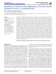
Fig. 1. Absolute ITD values averaged across 262 subjects.
Recent work related to HRTF personalisation includes deriving parametric models [3, 4], best-match selection from a database [5, 6], studying the mapping between anthropometric to acoustic features [1], tuning a low-dimensional HRTF representation [7], direct estimation from 3-D head models [8], and anthropometry-based HRTF modelling and synthesis [9, 10, 11, 12, 13]. An important cue encoded in the HRTF is the interaural time difference (ITD), i.e., the difference in the times of arrival of a sound at both ears. The ITD is a function of the sound’s direction of arrival as well as the listener’s anthropometry. The human auditory system relies on the ITD as a major localisation cue [14, 15]. Precise ITD modelling is crucial for accurate spatial rendering [16]. Commonly used geometric ITD models include the Woodworth model [17] and the spherical scatterer model [18]. Both approximate the head as a rigid sphere. These models have been extended to arbitrary ear angles [19] and ellipsoidal head shapes [20]. Previously, estimating ITDs from a 3-D head scan has been shown [21, 22], and the relationship between morphological changes and HRTF characteristics has been studied [23]. While these approaches showed promising results, their requirement of a full 3-D head scan may be difficult to meet in practical applications. Here we propose a method for personalising ITDs based on fitting a face template to a subject’s complete or partial head scan.
use an average ITD contour I¯ derived directly from measured HRTFs [12]. The average ITD contour of 262 subjects, measured at 400 locations [10] and interpolated at 2048 Fliege points distributed uniformly on the sphere [27, 28], is shown in Figure 1. Given the true ITD contour I, derived from a subject’s measured HRTF, the scaling factor s is derived as s = arg min s
N −1 X
(sI¯i + k) − Ii
�2
,
(3)
i=0
where N is the number of measurement directions and k an optional bias term. 2.3. Obtaining face template Fig. 2. a) High-resolution 3-D scan with 4096 uniformly distributed surface points (·) and 1583 face points (o); b) face template obtained from 262 high-resolution 3-D head scans. 2. PROPOSED METHOD The proposed method derives individual ITDs by applying a scaling factor, s, to an average ITD contour [12] (see Figure 1). The scaling factor is derived from the deformation of a face template matched to a head scan or depth image of the listener’s head. 2.1. Problem formulation The HRTF H(ω) for a specific direction of arrival can be described in the frequency domain as H(ω) = |H(ω)|e−iϕ(ω) ,
(1)
where ω is the angular frequency, and ϕ is the HRTF phase angle. For practical applications, the unwrapped phase angle ϕ is often considered to be linear, i.e., the ITD τ is assumed to be frequency independent [24, 19]: τ = tL − tR ,
(2)
where the tL and tR denote the time-of-arrival at the left and right ear entrance, respectively. While measured ITDs do exhibit frequency dependence [22], experimental findings indicate that it may not be perceptually relevant [25, 26]. The problem of personalising the ITDs of a generic HRTF consists in mapping the listener’s anthropometric features to the slope of the unwrapped phase angles ϕL and ϕR . 2.2. ITD modelling by scaling average ITD contour Geometric ITD models are typically based on the assumption that a listener’s ITD contour can be described with a simple model, parameterised via a few anthropometric features, e.g., the head width and the position of the ears. Here, we
Given a database of high-resolution 3-D head scans, an average face template S is derived. The scans are aligned so that the head is level, pointing forward, with the centre of the interaural axis lying at the origin of the Cartesian coordinate system (see Figure 2a). Using ray tracing, the vertices T of each 3-D head scan are resampled to give X p = [x0 x1 · · · xP ], the points of intersection between T and the normals of a cloud of points P uniformly distributed on the surface of a unit sphere [27] (see Figure 2a, black dots). A subset of G face points F = [f 0 f 1 · · · f G ] ⊂ X p is selected that satisfies vj fi · ≥ 0.5, (4) (∀i∃j) ||f i || ||v j || where (·) denotes the dot product, and V = [xv yv zv ]T is a matrix of directions. Here, V is chosen to roughly point to the front and cheeks of a 3-D scan: 1 cos(0.5) cos(−0.5) V = 0 sin(0.5) sin(−0.5) . 0 0 0 The green circles in Figure 2a mark the selected face points. The face template S = [s0 s1 · · · sL ] is obtained by averaging the Cartesian coordinates of the face point sets of all M 3-D head scans: M 1 X si = f . M m=1 i,m
(5)
The result of averaging 262 scans is shown in Figure 2b. From the template S, a subset of “cheek” points C = [c0 c1 · · · cc ] is obtained that satisfy (∀i) |yc,i | > 0.06,
(6)
where ci = [xc,i yc,i zc,i ]T and yc,i is given in metres. These points, illustrated by blue circles in Figure 2b, are used to estimate the deformation factor of the matched template, as discussed in Section 2.5.
Fig. 3. Fitting the face template to a (Kinect) depth image; a) raw input depth points; b) depth image after ICP alignment with face template; c) face template after NR-ICP deformation. 2.4. Deforming template to match depth image
3. EXPERIMENTAL EVALUATION
Given a 3-D head scan or a depth image of the listener’s face taken from a frontal view, a set of semi-uniformly distributed face points F on the scan surface is obtained via the procedure described in Section 2.3. To align the target face F with the face template S, an iterative closest point (ICP) transform is performed, yielding the aligned target Fˆ . The face template S is matched to the face points Fˆ using a nonrigid iterative closest point (NR-ICP) algorithm proposed by Amberg et al. [29]. Figure 3 illustrates the process of fitting the face template to a single depth image.
Ground-truth scaling factors for 180 high-resolution 3-D scans and their corresponding measured HRTFs were calculated via (3). For each of the scans, the face template was matched (see Section 2.4) and the deformation factors d∆ and dw were calculated via (8) and (10). Then, (11) was solved as s = 4.0849d∆ + 1.0064
(12)
s = 3.9343dw + 0.4218.
(13)
and
ˆ a deformation factor d is deGiven the deformed template S, rived by comparing the y-coordinates of the subset C before ˆ after the transformation: the NR-ICP transformation and C
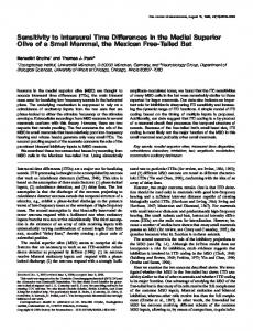
Figure 5 shows the deformation factors of 180 scans plotted against their ground-truth scaling factors. For reference, the correlation between the ground-truth scaling factors and the head-widths a measured manually with a pair of calipers is shown for 136 subjects, yielding
y∆,i = yc,i − yˆc,i .
s = 0.0257a + 0.6054.
2.5. Estimating ITD scale from template deformation
(7)
The deformation constant is given as: d∆ = median (y∆,i ) .
(8)
This simple measure for the template deformation was chosen for its robustness when applied to noisy depth images. Alternatively, if high-resolution 3-D scans are used that contain both the subject’s frontal and side views, yw can be calculated as: yw,i = ||CL,i − CR,i ||, (9) where CL and CR,i are left and right cheek points, respectively (cf. (6)). The deformation constant is given as dw = median (yw,i ) ,
(10)
in analogy to (8). The deformation factor d is mapped to the ITD scaling factor s via linear regression: s = k0 d + k1 .
(11)
(14)
Both deformation factors and manually measured headwidths correlate quite well with the ITD scaling factors. To assess the accuracy of the proposed method, the errors for estimating the ITD scaling factor as well as the raw ITD estimation errors are calculated. Results are shown in Section 3 for using s = 1 (“1”), the mean scaling factor (“mean”), s derived from measured head width (“head width”), and the ground-truth scaling factor (“optimal”). As a baseline, the ITD estimation errors of a parametric spherical head model [20] are provided: τˆ = c−1 ropt (ϕ + sin(ϕ)) ,
(15)
where c = 343 m/s is the speed of sound, ϕ is the lateral angle, and ropt is the optimal sphere radius in the least-squares sense. The proposed method yields the lowest errors for the
True scaling factor cheek_regression xshift
1.1
1.05
sˆ
sˆ
1.05 1
true scaling factor cheek xshift
1.1
1
0.95
0.95
0.9
0.9
0.85
0.85 20
40
60
80
100
2
120
a)
4
6
subject no. c)
image no. b)
Fig. 4. a) Example scenes used in evaluation; b) repeated runs using same subject, shown in a); c) comparison of ground-truth ITD scaling factor vs. proposed scaling factor estimates. 0.04
0.2
r = 0.79 dw
d∆
r = 0.76 0
0.15
-0.04
0.1 0.9
1
1.1
0.9
d∆
0.2
[cm] head width
s r = 0.99
0.15 0.1 -0.05
0
dw
0.05
1
1.1
s
20
r = 0.59 15 10 0.9
1
1.1
spherical [20] 1 mean head width dw d∆ optimal
s
ITD [ms]
ITD80 [ms]
NA 0.0375 0.0359 0.0270 0.0222 0.0234 0
0.0438 0.0405 0.0400 0.0359 0.0372 0.0373 0.0357
0.0487 0.0411 0.0401 0.0320 0.0315 0.0322 0.0242
Table 1. Root-mean-squared errors for estimating the scaling factor s, for the predicted perceived lateral angle, for the estimated ITD and for ITDs at extreme lateral angles (ITD80 ).
s
Fig. 5. Scatter plots of ground-truth ITD scaling factor vs. the face template deformation factor estimates and the manually measured head widt; r denotes the correlation coefficient. scaling factor estimation, and comparable results for the ITD RMSE. ITD80 is the RMSE for lateral angles greater than 80 degrees. For the proposed method, it is lower than the ITD RMSE averaged over all directions. This suggests that the scale of individual ITDs is captured by the scaled average contour, but that deviations across lateral angles remain. The results show that the proposed method successfully relates the deformation of the face template to an HRTF feature. To test the robustness of the proposed method, 123 depth images of the same subject were collected using a Kinect depth camera [30]. The images were collected in two different environments, with slightly differing lighting conditions and head orientations and positions (see Figure 4a). Figure 4b shows the estimated ITD scaling factors. While the estimates seem to exhibit a small bias relative to the ground-truth, especially for dw , the variance is quite low, indicating that the proposed method is relatively robust across test conditions. For seven of the subjects in the database with known ITD
measurements we collected Kinect depth images similar to the one shown in Figure 3a. Figure 4c shows the estimated ITD scaling factors. It can be seen that they correspond quite well to the ground truth. 4. SUMMARY AND CONCLUSION A method for personalising interaural time differences (ITDs) based on aligning and deforming a face template to a subject’s head scan is proposed. The method is evaluated using a database of high-resolution 3-D head scans and measured head-related transfer functions (HRTFs). As a proof of concept, it is applied to incomplete scans obtained from single-frame depth images. Experimental results indicate that the proposed method performs comparably to using manually measured head-width as an anthropometric feature, and appears relatively robust when used with incomplete head scans. We conclude that applying template matching to depth image data may provide an interesting avenue for personalising HRTFs. Future work includes experimenting with and improving the extraction of a deformation metric from the template matching process and applying it to other aspects of HRTF personalisation.
5. REFERENCES [1] C. Jin, P. Leong, J. Leung, A. Corderoy, and S. Carlile, “Enabling individualized virtual auditory space using morphological measurements,” in Proc. 1st IEEE Pacific-Rim Conf. Multimedia, Sydney, Australia, 2000, pp. 235–238. [2] S. Xu, Z. Li, and G. Salvendy, Individualization of HeadRelated Transfer Function for Three-Dimensional Virtual Auditory Display: A Review, pp. 397–407, Springer Berlin Heidelberg, Berlin, Heidelberg, 2007. [3] Y. Haneda, S. Makino, Y. Kaneda, and N. Kitawaki, “Common-acoustical-pole and zero modeling of head-related transfer functions,” IEEE Trans. Speech and Audio Process., vol. 7, no. 2, pp. 188–196, 1999. [4] V. R. Algazi, R. O. Duda, R. Duraiswami, N. A. Gumerov, and Z. Tang, “Approximating the head-related transfer function using simple geometric models of the head and torso,” J. Acoust. Soc. Am., vol. 112, no. 5, pp. 2053–2064, 2002. [5] D. Zotkin, J. Hwang, R. Duraiswami, and L. Davis, “HRTF personalization using anthropometric measurements,” in Proc. IEEE Workshop on Applicat. Signal Process. to Audio and Acoust. (WASPAA), New Paltz, NY, USA, 2003, pp. 157–160. [6] D. Sch¨onstein and B. F. G. Katz, “HRTF selection for binaural synthesis from a database using morphological parameters,” in Proc. Int. Congr. Acoustics, Sydney, Australia, 2010. [7] K. J. Fink and L. Ray, “Tuning principal component weights to individualize HRTFs,” in Proc. IEEE Int. Conf. Acoust., Speech, and Signal Process. (ICASSP), 2012, pp. 389–392. [8] C. T. Jin, P. Guillon, N. Epain, R. Zolfaghari, A. van Schaik, A. I. Tew, C. Hetherington, and J. Thorpe, “Creating the Sydney York morphological and acoustic recordings of ears database.,” IEEE Trans. Multimedia, vol. 16, no. 1, pp. 37–46, 2014. [9] P. Satarzadeh, V. R. Algazi, and R. O. Duda, “Physical and filter pinna models based on anthropometry,” in Proc. 122nd AES Conv., Vienna, Austria, 2007, Paper number 7098. [10] P. Bilinski, J. Ahrens, M. R. P. Thomas, I. J. Tashev, and J. C. Platt, “HRTF magnitude synthesis via sparse representation of anthropometric features,” in Proc. IEEE Int. Conf. Acoust., Speech, and Signal Process. (ICASSP), Florence, Italy, 2014, pp. 4501–4505. [11] F. Grijalva, L. Martini, S. Goldenstein, and D. Florencio, “Anthropometric-based customization of head-related transfer functions using Isomap in the horizontal plane,” in Proc. IEEE Int. Conf. Acoust., Speech, and Signal Process. (ICASSP), Florence, Italy, 2014, pp. 4473–4477. [12] I. Tashev, “HRTF phase synthesis via sparse representation of anthropometric features,” in Proc. Inform. Theory and Applicat. Workshop (ITA), San Diego, CA, USA, 2014. [13] J. He, W.-S. Gan, and E.-L. Tan, “On the preprocessing and postprocessing of HRTF individualization based on sparse representation of anthropometric features,” in Proc. IEEE Int. Conf. Acoust., Speech, and Signal Process. (ICASSP), Brisbane, Australia, 2015. [14] J. Blauert, Spatial Hearing - Revised Edition: The Psychophysics of Human Sound Localization, The MIT Press, Cambridge, MA, USA, 1996. [15] F. L. Wightman and D. J. Kistler, “Factors affecting the relative salience of sound localization cues,” in Binaural and Spatial
Hearing in Real and Virtual Environments, R. H. Gilkey and T. R. Anderson, Eds., pp. 1–23. Lawrence Erlbaum Associates, Mahwah, USA, 1997. [16] V. R. Algazi, C. Avendano, and R. O. Duda, “Estimation of a spherical-head model from anthropometry,” J. Audio Eng. Soc., vol. 49, no. 6, pp. 472–479, 2001. [17] R. S. Woodworth and G. Schlosberg, Experimental Psychology, Holt, Rinehard and Winston, NY, 1962. [18] G. F. Kuhn, “Model for the interaural time differences in the azimuthal plane,” J. Acoust. Soc. Am., vol. 62, no. 1, pp. 157– 167, 1977. [19] N. L. Aaronson and W. M. Hartmann, “Testing, correcting, and extending the Woodworth model for interaural time difference,” J. Acoust. Soc. Am., vol. 135, no. 2, pp. 817–823, 2014. [20] R. O. Duda, C. Avendano, and V. R. Algazi, “An adaptable ellipsoidal head model for the interaural time difference,” in Proc. IEEE Int. Conf. Acoust., Speech, and Signal Process. (ICASSP), Washington, DC, USA, 1999, pp. 965–968. [21] H. Gamper, M. R. P. Thomas, and I. J. Tashev, “Estimation of multipath propagation delays and interaural time differences from 3-D head scans,” in Proc. IEEE Int. Conf. Acoust., Speech, and Signal Process. (ICASSP), Brisbane, Australia, 2015. [22] H. Gamper, M. R. P. Thomas, and I. J. Tashev, “Anthropometric parameterisation of a spherical scatterer ITD model with arbitrary ear angles,” in Proc. IEEE Workshop on Applicat. Signal Process. to Audio and Acoust. (WASPAA), 2015, pp. 1– 5. [23] R. Zolfaghari, N. Epain, C. Jin, J. Glaunes, and A. Tew, “Large deformation diffeomorphic metric mapping and fast-multipole boundary element method provide new insights for binaural acoustics,” in Proc. IEEE Int. Conf. Acoust., Speech, and Signal Process. (ICASSP), Florence, Italy, 2014, pp. 2863–2867. [24] D. Zotkin, R. Duraiswami, and L. Davis, “Rendering localized spatial audio in a virtual auditory space,” IEEE Trans. Multimedia, vol. 6, no. 4, pp. 553–564, 2004. [25] A. Kulkarni, S. K. Isabelle, and H. S. Colburn, “Sensitivity of human subjects to head-related transfer-function phase spectra,” J. Acoust. Soc. Am., vol. 105, no. 5, pp. 2821–2840, 1999. [26] Z. A. Constan and W. M. Hartmann, “On the detection of dispersion in the head-related transfer function,” J. Acoust. Soc. Am., vol. 114, no. 2, pp. 998–1008, 2003. [27] J. Fliege and U. Maier, “A two-stage approach for computing cubature formulae for the sphere,” in Mathematik 139T, Universit¨at Dortmund, 44221, 1996. [28] J. Ahrens, M. R. P. Thomas, and I. Tashev, “HRTF magnitude modeling using a non-regularized least-squares fit of spherical harmonics coefficients on incomplete data,” in Asia-Pacific Signal Information Process. Assoc. Annu. Summit and Conf. (APSIPA ASC), 2012, 2012, pp. 1–5. [29] B. Amberg, S. Romdhani, and T. Vetter, “Optimal step nonrigid ICP algorithms for surface registration.,” in Proc. IEEE Conf. Comput. Vision and Pattern Recognition (CVPR). 2007, IEEE Computer Society. [30] “Kinect for Xbox 360,” http://www.xbox.com/ en-US/xbox-360/accessories/kinect.