Journal of Physics: Conference Series
Related content
Interface Circuit Design for Frequency-Time Domain MEMS Sensors
- RF-MEMS Technology for HighPerformance Passives: Introduction to MEMS and RF-MEMS: From the early days of microsystems to modern RFMEMS passives J Iannacci
To cite this article: Sergey Y Yurish and Nikolay V Kirianaki 2006 J. Phys.: Conf. Ser. 34 101
- Automotive MEMS sensors based on additive technologies A A Vasiliev, A V Sokolov, A V Pisliakov et al.
View the article online for updates and enhancements.
- A novel design and analysis of a MEMS ceramic hot-wire anemometer for high temperature applications N R Nagaiah, A K Sleiti, S Rodriguez et al.
This content was downloaded from IP address 178.171.21.164 on 24/02/2018 at 10:55
Institute of Physics Publishing doi:10.1088/1742-6596/34/1/017
Journal of Physics: Conference Series 34 (2006) 101–105 International MEMS Conference 2006
Interface Circuit Design for Frequency-Time Domain MEMS Sensors SERGEY Y. YURISH Information Systems and Networks, National University Lviv Polytechnic, Bandera str., 12 Lviv, 79013, Ukraine
[email protected] http://www.sensorsportal.com NIKOLAY V. KIRIANAKI International Frequency Sensor Association (IFSA), Bandera str., 12 Lviv, 79013, Ukraine
[email protected] Abstract. The focus of this paper is to describe emerging techniques and methods for interface circuit design for frequency, period, duty-cycle or PWM output MEMS sensors. The designed module is intended for frequency-time parameters – to – digital conversion and communication functions and can be embedded into a SoC. The developed interface circuit provides technologies that both reduce the cost and time of SoC development and improve sensor system performance. Its revolutionary suite of technical products facilitates, for the first time, low-cost, time-efficient production of MEMS sensor applications. On the other hand the proposed design approach reduces the development time, risk and cost of sensor applications by to ten times. Keywords: MEMS; frequency-time domain sensors.
1. Introduction According to NEXUS market analysis on ‘MEMS and Microsystems III, 2005-2009’1 markets for microsystems will double over the next five years from $12 billion in 2004 to $25 billion in 2009, resulting in a CAGR of 16%. According to the Yole Development report2, the MEMS device market was $3.84 billion and is forecasted to reach $5.6 billion at the end of 2005 and $7.0 billion in 2007, resulting in a 17% CAGR. However, growth rate will differ depending on the MEMS applications. New developments of MEMS devices (from R&D to first production) take now 3 to 6 years and the development/adaptation of a new device on an existing process takes as usually 2 to 3 years (from R&D to first production). The most popular and promised MEMS devices markets are the following: acceleration sensors, gyroscopes, pressure sensors, ink jet heads, optical MEMS (DLP, bar code readers, fiber optics components), silicon microphones, RF MEMS, and microbolometers2. Application areas are: consumer, space/military, automotive, medicine and telecommunications. However, one key point of
© 2006 IOP Publishing Ltd
101
102
optical MEMS is that the applications have very different characteristics and for the moment, only few are volume markets (display and bare code readers)3. The use of IC compatible process lines for MEMS production is growing. There are clearly high benefits in using CMOS or BiCMOS-compatible manufacturing lines to target high-volume MEMS markets such as automotive and IT devices. There is a general trend toward adoption of more integrated solutions. Some specific reasons to select monolithic integration as a solution: cost advantages, commercial imperatives, performance advantages, and pragmatism4. Nevertheless, hybrid solutions are still sometimes preferred as it offers distinct advantages (more flexible manufacturing strategy, shorter development time, simpler and more easily available manufacturing process...). Integrated MEMS market share is expected to grow in the future. However there are today still bottlenecks to be overcame (process standardization, MEMS is not always a large volume market ...). Interface circuit design has become a strategic technology for modern System-On-Chip (SoC) including MEMS sensors, interfacing, processing and communication modules. It may also be the bottleneck for faster progress. Modern CMOS technologies allows manufacturers to greatly enhance silicon-based MEMS sensors by integrating signal conditioning, signal processing, digital output options, diagnostics and communications on a SoC. Using frequency-time domain MEMS sensors in this design gives more precise control in comparison with tradition analog (voltage or current) sensor outputs. Such approach delivers enhanced accuracy and reliability due to high precision sensors, for example, 0.01 % FS error for modern frequency output pressure sensors5. Interface circuit design can be made in frame of so-called Intelligent Sensing Architecture6. It uses a cell-based approach to SoC design and layout at which individual circuit blocks or modules are designed and each block is optimized independently. By having characterization and simulation of each block it is possible to assemble the appropriate modules for a given SoC design and more accurately predict the performance of the sensor system. With this approach, development time and expense will be less because pre-existing technology can be used. One of success attempt to overcome the mentioned bottlenecks was developed by IFSA and SWP, Inc. (Toronto, Canada) the IC of Universal Frequency-to-Digital Converter (UFDC-1) compatible with MEMS-based time-domain output sensors7. The UFDC-1 provides the technologies that both reduce the cost and time of sensor application development and improve digital sensor performance. It is a multi sensor data acquisition and signal processing system with three popular sensor interfaces: SPI, I2C and RS-232. The MEMS on IC technologies are taking a very important market share compared to total MEMS activities. Taking into account the high accuracy of modern frequency output and wide frequency range from some parts of Hz up to some MHz8 in order to be neglected in a measuring channel, the frequency-tocode conversion relative error must be in order or at least in five times less than the sensor’s error. Therefore, the frequency must be measured with 0.001 % or at least, 0.002 % relative error. It is evidently that no any classical frequency-to-digital conversion methods can be used in the modern design. Moreover, interface circuit design, therefore, requires specific and interdisciplinary knowledge as well as special techniques in order to achieve the reliability and the performance demanded by the user 9.
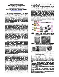
2. Sensors Interfacing IC In order to eliminate these design problems the novel interfacing module for MEMS-based sensors was developed and used in SoC design in frame of approach similar to the Intelligent Sensing Architecture design methodology. The designed low-power module (Figure 1) contains measuring and communication units. The first one has two channels and converts any from 14 frequency-time parameters to digital according to novel patented measuring methods with programmable relative error from 1 % up to 0.001 %. The frequency range is from 0.05 Hz up to 7.5 MHz without prescalling. The
103
measuring unit uses an advanced frequency-to-digital conversion method with non-redundant conversion time and constant programmable quantization error in all frequency range. The communication block lets create true digital output according to RS-232 interface or serial SPI and I2C communication buses.
Fig. 1. Interfacing module for frequency-time domain MEMS sensors. The present trend is to include several MEMS sensors on the same chip, together with their associated interfaces and the required signal processing (Figure 2).
Fig. 2. Possible architectures for a multi-sensor system.
104
The designed module is very suitable for such applications and can be used at SoC design. Figure 2 shows possible architectures for multi-sensor systems (a- SoC based on pressure and temperature MEMS sensors with frequency outputs; b – optical MEMS sensors with duty-cycle and frequency outputs). The output of each sensor transferred from frequency-time signal domain to the digital by the universal frequency-to-digital converter (UFDC). Finally, the signals obtained are delivered to communication channel through on-chip bus interfaces. As an example, let us to consider a multiparameter sensor system, which contain frequency output pressure and temperature sensors and appropriate interfacing circuitry based on the UFDC-1.
3. Multiparameter Sensor System New analysis from Frost & Sullivan (www.sensors.frost.com), World Pressure Sensors and Transmitters Market, reveals that the market earned revenue of $4,018.8 million in 2004 and projects to reach $5,545.1 million in 201110. The pressure sensors market also has progressed towards digital electronics, which are in demand for multiple end-user applications. More developments in the high-end pressure sensors are also expected. There has been a demand for the software integration, which includes software programs to collect and assess data. This provides higher control of the process, as the data received by the operator is a sort of recommendation to help improve the process. End-users prefer buying pressure transmitters with software integration and hence manufacturers are forced to address these needs. As a result, to help manufacturers and customers to design digital output pressure sensors and transducers very quickly, the UFDC-1 also can be used in order to reduce time-to-market and production cost 11. The multiparameter MEMS based sensor system can be directly connected to the UFDC-1 as it is shown in Figure 3. The temperature frequency signal is connected to the first channel of the UFDC-1, the pressure frequency signal is connected to the second channel. + 5V
7
Pressure
Temperature
22
Fig. 3. Multiparameter MEMS based sensor system.
Appropriate commands (RS-232 interface) for the UFDC-1 operation mode for frequency–to– digital conversion in both channels with 0.001 % relative conversion error are shown in Figure 4. The different conversion error can be chosen for each of channel.
105
>M0; Frequency measurement initialization in the first channel >A0; Choose the conversion error 0.001 % >S; Start a measurement >R; Read a result proportional to temperature >ME; Frequency measurement initialization in the second channel >A0; Choose the conversion error 0.001 % >S; Start a measurement >R; Read a result proportional to pressure Fig. 4. Appropriate UFDC-1 commands (RS-232) for frequency-to-digital conversion in both cannels with 0.001 % relative error.
One more interesting feature of the UFDC-1 based systems is a self-adaptation. The quantization error can be changed during the conversion process depend on condition of measurement in order to have, for example, minimum possible conversion time at critical points of pressure range. 4. Conclusions Combining silicon micromachining designs and processes with the interfacing circuit design based on the Universal Frequency-to-Digital Converter overcomes many of the early limitations of single-chip sensors. This co-integrated unit can be produced using, for example, co-integration technology or hybrid technology. By eliminating the need for ADC, the frequency-to-digital conversion schemes reduce the systems complexity. The results are high-performance single-chip pressure sensors with truly digital output (RS-232 interface) or bus output (SPI or I2C) at significant reduction of production costs, time-to-market and simplification of the design process. The designed interface circuit provides technologies that both reduce the cost and time of SoC development and improve sensor system performance. Its revolutionary suite of technical products facilitates, for the first time, low-cost, time-efficient production of MEMS sensor applications. On the other hand the proposed design approach reduces the development time, risk and cost of sensor applications by to ten times.
References [1] MEMS and Microsystems III, 2005-2009, NEXUS [2] Ultimate MEMS market Analysis, April 2005 [3] Analysis of Optical MEMS Applications for Non Telecom Markets, January 2005 [4] MEMS on IC: Analysis of the Applications and Technology Trends, November 2004 [5] N.V. Kirianaki, S.Y. Yurish, N.O. Shpak, V.P. Deynega, Data Acquisition and Signal Processing for Smart Sensors, (John Wiley & Sons, Chichester, UK, 2002). [6] M.D. Naik and M.L. Dunbar, CMOS-Based Smart Sensors, Sensors, May (1997), 22-26. [7] Universal Frequency-to-Code Converter (UFDC-1). Specification and Application Notes (2004) http://www.sensorsportal.com/DOWNLOADS/UFDC_1.pdf [8] Smart Sensors and MEMS, Ed. by Sergey Y. Yurish and Maria Teresa S.R. Gomes, (Kluwer Academic Publishers, 2004). [9] A. Baschirotto, P. Malcovati, Technology-Driven Alternatives for Smart Sensor Interfaces, in Sensors Update 13, Ed. by H. Baltes, G.K. Fedder and J.G.Korvnik, (Wiley-VCH, 2004), pp.45-81. [10] World Pressure Sensors and Transmitters Market, F545-32, (Frost & Sullivan), http://www.sensors.frost.com [11] S.Y. Yurish, Intelligent Digital Pressure Sensors and Transducers Based on Universal Frequencyto-Digital Converter (UFDC-1), Sensors & Transducers Magazine 60 (2005) 432-438.