experimentation proves to be the most demanding phase for conducting FRTS, since it requires concurrent monitor- ing and management of both the real system ...
.
INTRODUCING
UML MODEL FOR FASTER-THAN-REAL-TIME SIMULATION
Dimosthenis Anagnostopoulos George-Dimitrios Kapos
Vassilis Dalakas* Mara Nikolaidou*
Harokopio University of Athens 70 El. Venizelou Str, 17671 Athens, Greece email: {dimosthe, gdkapos}@hua.gr
*University of Athens Panepistimiopolis, 15771 Athens, Greece email: {vdalakas, mara}@di.uoa.gr
ABSTRACT Faster-than-real-time simulation (FRTS) is used when attempting to reach conclusions for the near future. FRTS experimentation proves to be the most demanding phase for conducting FRTS, since it requires concurrent monitoring and management of both the real system and the simulation experiments. Having previously introduced a conceptual methodology and specification for conducting FRTS experiments, we now propose an implementation framework, based on the Real Time Unified Modeling Language (RT-UML). The derived RT-UML model includes specific timing attributes and is independent of the application examined via FRTS. Thus, implementation of FRTS program modules can be analyzed and realized, following the guidelines of this model, ensuring the reliability of the results within predetermined time frames. A pilot application regarding FRTS implementation based on the proposed RT-UML model and related experience is also discussed in the paper. 1
INTRODUCTION
Faster-than-real-time simulation is used when attempting to reach conclusions for the near future [1]. In this type of simulation, advancement of simulation time occurs faster than real world time. Real time systems often have hard requirements for interacting with a human operator or other agents [2]. Current FRTS research directions involve the distribution of the experiment over a network of workstations, intelligent control [3] and fault diagnosis [4], interactive dynamic simulation [5] and modeling formalisms [6]. In [7] a conceptual methodology for FRTS was described, aiming at providing a framework for conducting experiments dealing with the complexity and the hard realtime requirements. The following simulation phases have been identified: modeling, experimentation and remodeling. During experimentation, both the system and the model evolve concurrently and are put under monitoring. Data depicting their consequent states are obtained and stored after predetermined, real-time intervals of equal
length, called auditing intervals. In the case where the model state deviates from the corresponding system state, remodeling is invoked. This may occur due to system modifications, involve its input data, operation parameters and structure [7]. Modeling issues and formalisms for structure modifications have been thoroughly studied either at the methodological level [8], [9], or for domain/oriented approaches, such as computer networks [10]. To deal with system modifications, remodeling adapts the model to the current system state. This should be accomplished without terminating the real time experiment, that is, without performing recompilation. When model modifications are completed, experimentation resumes. Remodeling can also be invoked when deviations (expressed through appropriate statistical measures) are indicated between the system and the model due to the stochastic nature of simulation, even when system parameters/components have not been modified. Finally, in case simulation results (predictions for the near future) are considered to be valid, an additional phase, called plan scheduling, is invoked to take advantage of them [7]. Experimentation phase comprises monitoring, that is, obtaining and storing system and model data during the auditing interval, and auditing, that is, examining a) if the system has been modified during the last auditing interval (system reformations), b) if the model no longer provides a valid representation of the system (deviations) and, c) if predictions should be used in plan scheduling. Evidently, if conditions (a) or (b) are fulfilled, remodeling is invoked without examining condition (c). As the system dynamic behavior may result in critical modifications of the system input data, operation parameters and structure, we distinguish three system reformation types. Specific measures are monitored to determine whether reformations have occurred. The variables used to obtain the corresponding values are referred as monitoring variables. Note that monitoring variables do not follow the single-valued definition of program variables. Auditing examines monitoring variables corresponding to the same real time points (i.e. the current system state and simula-
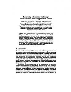
tion predictions for this point) and concludes for the validity of the model. Both system and model evolution in real time is depicted in Figure 1. Real time points are noted as ti. The states of the system and the model at point ti are noted as Ri and Si, respectively. When the model predicts the system state at tn (simulation time equal to tn) at real time point tx, we use the notation Sim(tx)= tn. Auditing is performed at tn-1, tn, tn+1 and, thus, compares states Sx and Rn at time point tn. If model validity is consecutively ensured within a number of consecutive auditing intervals [tn-2, tn-1], [tn-1, tn], …, it is likely that simulation predictions are also valid. Thus, plan scheduling is invoked to take advantage of predictions and experimentation resumes. s y s te m m o n ito rin g
s y s te m m o n ito r in g Rn
R n -1
t0
R n+ 1
R n+2
S n -1
Sx
Sy
Sn
S n+ 1
S n+ 2
t n -1
tx
ty
tn
tn + 1
tn+ 2
a u d i t in g re m o d e lin g
m o d e l m o n ito rin g a n d e x e c u tio n
Figure1: Experimentation in FRTS Experimentation is the most demanding phase of FRTS, since strict time restrictions are imposed: Within an auditing interval, model initialization and execution must take place faster than the real system, while auditing and remodeling must be completed within a small fraction of the auditing interval. In fact, experimentation phase can be viewed as a “real time system” itself. In order for an FRTS experiment to be successful, time restrictions should be studied prior to FRTS implementation. Thus, it is essential to provide a model for experimentation activities and their interrelations, facilitating the FRTS researcher to determine the conditions under which such an experiment is feasible, e.g. to determine the auditing interval, the infrastructure need to execute simulation model, e.t.c. Furthermore, while modeling/remodeling and model execution strongly depend upon the real system, auditing and monitoring are real time activities, which can be implemented based on the same principles for all FRTS experiments [10]. In [11] and [12], a specification of data exchange among simulation components was provided and emphasis was given in activity control and experimental state transition. As simulation activities and control data flows may be the same in diverse FRTS implementations, a common basis for FRTS system development was introduced.
In the following, we introduce a model for FRTS experimentation phase, emphasizing monitoring and auditing activities, which are not domain-oriented. The proposed model aims at establishing common guidelines for FRT simulator development and facilitating its implementation in different platforms according to each researcher’s specific need. We decided to adopt UML for FRTS modeling, since it is widely used industry standard and facilitates the automated model implementation in different platforms using a variety of existing tools.Descriptive capabilities of distinct types of UML diagrams are utilized to specify different aspects of FRTS systems: distinct entities and their roles, overall down to detailed logic of FRTS system, synchronized communication, and data specification. Furthermore, in the proposed specification we use elements from the OMG UML Profile for Schedulability, Performance and Time Specification [13] (abbreviated by Real-Time UML or RT-UML). The profile, also used in [14], enables the detailed specification of critical time and synchronization requirements for FRTS components and an overall performance evaluation. Therefore, we provide a detailed and integrated specification for FRTS systems, leading to standardized implementations of such systems that meet strict time requirements. Implementation may also be facilitated with the use of tools that support code generation given a UML model. This suggests automated program generation and execution during FRTS. In section 2 we review UML and RT-UML used in the specification of FRTS systems. An overview of the model, emphasizing on the identification of the discrete roles for actors and entities within FRTS, is presented in section 3. FRTS system modeling, focusing on timing issues, is given in section 4. Detailed RT-UML diagrams of FRTS system components specify how each component implements its functionality in terms of events, activities, and actions, emphasizing on timing constraints. In section 5 an simple implementation example is used to illustrate the benefits of RT-UML modeling of FRTS. Finally, in section 6, conclusions are drawn. 2
RT-UML MODELING FRAMEWORK
Unified Modeling Language (UML) [15, 16] is the result of an effort to unify concepts among distinct methodologies, made by the authors of three leading methodologies – Rumbaugh, Booch, and Jacobson. Currently, UML has been adopted as a standard by the Object Management Group (OMG) and is considered a fundamental skill for software engineers. UML does not provide the required degree of precision (regarding timing issues) for the specification of FRTS. Thus, we use RT-UML [13], which enhances UML diagrams. RT-UML does not propose new model analysis techniques, but it rather enables the annotation of UML models with properties that are related to modeling of time
and time-related aspects. Therefore timing and synchronization aspects of FRTS components are defined and explained in terms of standard modeling elements. RT-UML has a modular structure that allows users to use only the elements that they need. It is divided into two main parts (General Resource Modeling Framework and Analysis Models) and is further partitioned in six subprofiles, dedicated to specific aspects and model analysis techniques. Since the emphasis of this work is on time and concurrency aspects of FRTS systems, we only use elements from the General Time Modeling and General Concurrency Modeling subprofiles. Each subprofile provides several stereotypes with tags that may be applied to UML models. A stereotype can be viewed as the way to extend the semantics of existing UML concepts (activity, method, class, etc.). For example, a stereotype can be applied on an activity, in order to extend its semantics to include the duration of its execution. This is achieved via a new tag added to the activity, specifying the execution duration. Stereotypes define such tags and their domains. The proposed FRTS model consists of RT-UML enhanced diagrams, which are annotated according to the conventions used in the RT-UML profile specification and its examples [13]. Stereotypes applied to classes in class diagrams are displayed in the class box, above the name of the class (a in Figure 2). However, when tag values need to be specified for a certain stereotype, a note is also attached (b in Figure 2). In sequence diagrams, event stereotypes are displayed over the events, while method invocation and execution stereotypes are displayed in notes (c in Figure 2). In activity diagrams, notes are also used to indicate the application of a stereotype on an activity, state or transition (d in Figure 2).
ClassName
ClassName
Stereotype
Tags
Applied to
RTaction
Activity, Method State
Activity
Event Method Event Class
Sequence Sequence Sequence Class
CRasynch
RTstart, RTend, RTduration RTstart, RTend, RTduration RTat RTtimerPar RTduration, RTperiodic -
Diagram type used in Activity and Sequence
Sequence
CRconcurrent CRimmediate
CRmain CRthreading
Method invocation Class Event
CRsynch
-
RTdelay
{tag1=value1, tag2=value2, ...}
RTevent RTnewTimer RTstart RTtimer
(b)
(a)
ObjectA
reference to the method that should be invoked once the object moves to “executing” state. RTtimer models a timer mechanism. Tag RTduration specifies the duration of the timer mechanism, while RTperiodic indicates whether the timer is periodic or not. In sequence diagrams we use the RTevent, CRimmediate, CRsynch, CRasynch, RTnewTimer, RTstart and RTaction. RTevent models events of message dispatches, specifying the time instance they occur (through the RTat tag). CRimmediate is also used for message dispatches to indicate that no time is consumed until the message reaches its destination. The CRthreading tag of this stereotype defines the thread that will execute a method (as a result of the message): the thread of the receiver (value “local”) or the thread of the sender (value “remote”). CRsynch and CRasynch are used to indicate whether a method is invoked synchronously or not. Stereotype RTnewTimer models methods that create new timers and RTstart is used for events that start timing mechanisms. Finally, RTaction is used for methods, specifying the instance they start (tag RTstart) and their duration (tag RTduration). In activity diagrams we use the RTaction and RTdelay stereotypes. RTaction was described earlier, while RTdelay is used for pure delay states, specifying their start, end and duration. Table 1 summarizes the RT-UML stereotypes used in the proposed FRTS model, their tags, the concepts applying to, and the diagram types they are used in.
ObjectB State1
Activity
State2
Method invocation
Class Sequence diagram Sequence diagram
Table 1: RT-UML Notation (d)
(c)
Figure 2: RT-UML notation The RT-UML stereotypes used in this paper focus on timing, concurrency and synchronization issues, providing considerable precision in the specified model. In class diagrams of this paper we use the CRconcurrent and RTtimer stereotypes. CRconcurrent is used for classes of objects that may be executed concurrently. A CRmain tag holds a
3
FRTS: A HIGH-LEVEL DESCRIPTION
An object-oriented specification of FRTS is provide in this section. In Figure 3, a UML use case diagram is depicted, including all entities involved in FRTS. Both the system and the model, are separate from the main module of FRTS and handled independently. System environment (SE) represents the actual system and a surrounding mechanism
facilitating system monitoring. It is considered as a separate entity that interacts with the FRTS system. Model environment (ME) includes the model and its execution environment (MEE), while the FRTS System process is the software module responsible for controlling FRTS. Finally, the user is the actor that enables the whole process, providing the case study. The user provides the experiment specifications and manages the FRTS System process by starting or stopping the experiment. System and model environment entities provide raw system data and raw model data, respectivelyThe FRTS System process performs auditing to identify potential deviations between the model and the system. In case such a deviation is indicated exceeding a respective remodeling threshold, remodeling is invoked (Remodeling), which results in the construction of a new model that replaces the one currently used (Model management).
Start
Uninitialized Set Experiment Specifications Initialized Stop
Start Operational
Start System Monitoring Initialize Model
Start Model
Start Model Monitoring
User
FRTS System
start/stop FRTS
Waiting (model is running) FRTS Management Uses
Uses
Uses
Experiment specifications provision
[ Valid ] Audit Interval State Interval State Audit
Model management
Remodeling
Pause Model
Auditing
Audit
[ Invalid ] System data provision
[ Valid ]
Raw model data provision
[ Invalid ] Remodel
System Environment
Resume Model
Model Environment
Figure 3: FRTS detailed use case diagram
Figure 4: FRTS System activity diagram
We focus on the FRTS System, as the FRTS coordinating entity. The activity diagram depicted in Figure 4 provides a description of FRTS System process. The user is obliged to provide experiment specifications to the process with the SetExperimentSpecifications command. Then, start initiates the experiment, transiting to the Operational state. As previously stated, system monitoring is considered to be performed autonomously by the real system with the aid of expert sensors that store monitoring information. The contribution of Start System Monitoring activity is restricted in stimulating the aforementioned sensors to start collecting and recording data by sending the appropriate event to SE.
Based on the experiment specifications, an initial model is being created (Initialize Model activity) using classes from predetermined libraries. Model environment is considered separate from the FRTS environment (e.g. it could be a DEVS-based execution environment). Therefore, Start Model activity simply tells ME to start simulation and is used for synchronization purposes. Model monitoring is considered to be performed by the ME which stores monitoring data. Thus, model and system monitoring are performed concurrently and autonomously, collecting data from both. Model monitoring is executed for a time period equal to auditing interval, such as [tn-1, tn] in Figure 1, during which the FRTS System process mainly remains in state Waiting (Figure 4). Model execution is then paused and Audit is invoked. Audit determines if the model still
provides a valid representation of the system. If invalid, Remodel is invoked. Otherwise, MEE is informed to resume execution and monitoring of the model. UML semantics were adequate to represent FRTS system operation in a high-level of detail, since there was no need to represent timing constraints between FRTS specific activities and system/model environment. In a smaller time interval (state interval) than the auditing interval, the FRTS System process leaves Waiting state, to perform the State Audit activity. State Audit handles critical, such as structural, modifications of the real system, where remodeling must be performed instantly to restore consistency between the model and the system. Model monitoring is disabled during Audit and Remodel. On the other hand, system monitoring is never terminated, so that system changes can always be perceived. The only modification it experiences is that it is restarted for synchronization purposes after Remodel. 4
4.1 FRTS Components Figure 5 depicts the FRTS system design, based on a set of classes and interfaces. The classes are shortly described below (detailed descriptions are given in following subsections): • Context is a utility class, used for storing the experiment specifications, references to the system monitor and the model environment, and monitoring variable values used for state auditing. • Control class initiates the FRTS process. • StateAuditor, Auditor, and Remodeller are responsible for performing the homonymous operations. • Timer is responsible for producing StateAudit and Audit events, necessary for triggering StateAuditor and Auditor. • Class UserInterface is simply the means for introducing user requests and data and therefore, is not further explained. The following interfaces are also used: • IAuditor interface defines the abstract behavior of an auditor and is implemented via StateAuditor and Auditor classes. • Monitor interface models the abstract concept of a monitor for variables’ values. Interfaces SystemMonitor and ModelExecutionEnvironment extend this interface to capture specific behavioral characteristics, required for system and model monitoring, respectively.
FRTS SYSTEM SPECIFICATION
In this section a specification for FRTS systems implementation is provided. First, FRTS system main classes and interfaces are presented in a class diagram. Then, FRTS main operations are presented using activity and sequence diagrams. RT-UML semantics are included in the diagrams in both case mainly to indicate concurrent execution of activities, the need for synchronization and timing constraints.
Context expSpecs : ExperimentSpecs systemMonitor : Monitor modelMonitor : ModelExecutionEnvironment lastStateMonVarsVals : MonitoringVars setExperimentSpecs() setModelInitializationParams() getSpecsFor() getStateVarVal() setStateVarVal()
Auditor IAuditor audit()
StateAuditor SystemMon itor
audit() {CRmain="stateAudit()"
{CRmain="start()"} {RTduration=d, RTperiodic=true}
{CRmain="remodel()"}
{CRmain="audit()"}
audit() buildAuditTree()
getStateVarsVals()
Monitor
Remodeller remodel()
startMonitoring() getVals() : MonitoringVars
ModelExecutionE nvironment
UserInterface Timer duration : Time mult : Integer Timer() start()
Control
{CRmain="start()"}
start()
Figure 5: The main FRTS system classes
initializeModel() startModel() pauseModel() resumeModel() deleteModel()
. Classes Control, Timer, StateAuditor, Auditor, and Remodeler are intended to run on separate threads and therefore have the CRconcurrent stereotype. Objects of each of these classes operate independently and occasionally concurrently. The CRmain tag of CRconcurrent stereotypes indicates the method that is executed when objects of each class are activated. Class Timer has also the RTtimer stereotype, indicating that it is a timing mechanism that generates an event. Tags RTduration and RTperiodic further define the behavior of this timing mechanism, specifying its duration and indicating whether it is periodic or not. No classes are specified for the system monitor and the model environment, since they are not part of the FRTS system. FRTS components require only communication interfaces with the system monitor and the model environment, denoted by SystemMonitor and ModelExecutionEnvironment.
start() event to the Control (through the UserInterface) at a random time instance ty. The start() event causes the immediate execution of the homonymous method of the Control, as indicated by the CRimmediateExecution stereotype. Value ‘local’ of the tag CRthreading shows that the start() method of Control is not executed by the thread of the invoking object (UserInterface), but by a separate, local thread of the Control. A ‘remote’ value on this tag would indicate execution of the method by the thread of the invoking object. The CRasynch stereotype indicates that the invocation of the start() method is asynchronous, i.e. the invoking object does not wait for the execution of the method to be completed. At this stage several initiation messages are exchanged until the FRTS process reaches its stable state of periodic audits and state audits. This happens when the last message (start()) is sent to the Timer that will repeatedly produce state audit and audit events from this point on. All method executions are annotated with the appropriate RTaction stereotypes that indicate when each execution starts (tag RTstart) and its duration (tag RTduration).
4.2 Initiation of the FRTS process Figure 6 shows the sequence of messages exchanged by the FRTS system objects during initiation. This sequence diagram of the FRTS process starts when the user sends the ui : UserInterface
control : Control
{RTat=(ty,'ms')} {CRthreading='local'} start( )
timer : Timer
modelExEnv : ModelExec...
{RTat=(ty+b,'ms')} {CRthreading='local'} startMonitoring( )
systemMonitor : Monitor Parameter 'b' is the time needed for a primitive operation to be performed {RTstart=(ty+b,'ms'), RTduration=(b,'ms')}
{RTat=(ty+2*b,'ms')} {CRthreading='local'} initializeModel(ModelInitializationParams)
{RTstart=(ty+2*b,'ms'), RTduration=(c,'ms')}
Parameter 'c' depends on modeling/remodeling etc.
{RTat=(ty+3*b+c,'ms')} {CRthreading='local'} startModel( ) {RTstart=(ty+3*b+c,'ms'), RTduration=(b,'ms')}
{RTat=(ty+5*b+c,'ms')} {CRthreading='local'} startMonitoring( ) {RTat=(ty+6*b+c,'ms')} {CRthreading='remote'} {RTtimerPar=x} Timer(RTtimeValue,Integer)
{RTstart=(ty+5*b+c,'ms'), RTduration=(b,'ms')}
{RTstart=(ty+6*b+c,'ms'), RTduration=(2*b,'ms')}
{RTat=(ty+9*b+c,'ms')} {CRthreading='local'} start() {RTstart=(ty+9*b+c,'ms'), RTduration=Infinite}
Figure 6: Sequence diagram for starting the FRTS process
The use of RT-UML in sequence diagram of Figure 6 clarifies thread synchronization and execution, determines event occurrence and action duration, and enhances its semantics. Thus, an in-depth and comprehensive view of the FRTS system is obtained. he activity diagram of Figure 7 defines the functionality of the start() method of class Control. Each activity of the diagram is annotated with the appropriate RTaction stereotype note. Using this kind of stereotype and its RTduration tag, activities’ durations are specified. The lower part (do/) of each activity defines the actions executed or messages sent. Message dispatches are denoted with the ^ symbol. The overall duration of start()method is 9*b+c ms, where b is the time needed for a basic operation to be performed (arithmetic operation, method invocation, etc.). Parameter c is the duration of model’s initialization and depends on the experiment specification. The overall duration of start() refers to the duration from the time instance when the user sends a start() event until everything has been initialized and Timer is started.
Start System Monitoring
Initialize Model
{RTduration=(b+c,'ms')}
do/ ^control.modelMonitor.initializeModel(control.expSpecs.modelInitParams)
ModelInitialized Start Model do/ ^context.modelMonitor.startModel()
{RTduration=(2*b,'ms')}
Parameter 'c' depends on modeling/remodeling etc.
ModelStarted Start Model Monitoring
{RTduration=(b,'ms')}
do/ ^context.modelMonitor.startMonitoring()
Create Timer do/ m=context.expSpecs.auditingInterval/context.expSpecs.stateInterval do/ ^Timer.new(context.expSpecs.stateInterval,m)
{RTduration=(3*b,'ms')}
TimerCreated Start Timer do/ ^timer.start()
RootNode orNum : Integer andNum : Integer ORsubtree : ORNode[] ANDsubtree : ANDNode[]
ORNode rcname : String tname : String mvname : String comp_params : Double systemvalue : OutputValues modelvalue : OutputValues
ANDNode weight : Double
{RTduration=(b,'ms')}
do/ ^context.systemMonitor.startMonitoring()
During auditing, system modifications, involving its input data, operation parameters and structure, as well as deviations between the system and the model are examined to determine model validity. If remodeling is required, a remodeling indication is produced. All monitoring variables are used in this process. Monitoring variable comparison is realized using the auditing tree, which is a conceptual tree structure. It is divided into two subtrees and includes two corresponding types of end nodes, OR and AND, as depicted in Figure 8. The audit activity constructs the auditing tree retrieving system and model monitoring variable entries from the System Monitor and Model Execution Environment, respectively.
{RTduration=(b,'ms')}
Figure 7: Activity diagram for method start of class Control 4.3 Audit Audit is the key experimentation activity determining model validity through comparing the corresponding system and model monitoring variables. Auditing is activated either after a state interval or an audit interval. Two distinct cases are thus considered: standard auditing and state auditing. Throughout this paper, the term auditing refers to standard auditing. State auditing is explicitly referenced.
Figure 8: Auditing tree class diagram Both Audit and State Audit execution are restricted by strict timing concerns, since in both cases the auditing tree must be constructed in a small fraction of the audit/state audit interval. Furthermore, the auditing tree construction is bounded by system and model environments since monitoring variable values must be fetched from both of them. These restrictions are denoted in detail in corresponding sequence and activity diagrams, where RT-UML use offers the ability to estimate the time elapsed in separate activities or the whole auditing process in total. Hence, bottlenecks regarding the execution time of specific Auditing and Model/System Environment processes (e.g. comparing values of a monitoring variable) may be identified during analysis and Auditing implementation performance can be measured and validated with regard to Model/System Environment operation. For example, since the FRTS Modeler is able to realize the way the overall duration of audit depends on the number of monitoring variables or the fetching mechanism of System Environment, he/she may regulate the operation of all FRTS modules. In figures 9 and 10, the State Audit RT-UML sequence and activity diagrams are presented. As shown in figure 9, state audit activity inspects the current system state to determine if reformations have occurred. In this case, the model no longer provides a valid representation and the relevant remodelling indication is produced. As indicated in the activity diagram in figure 10, only variables designated as state monitoring variables are retrieved dur-
ing state audit. Each of these variables is compared to its previous known value and the newer is stored. If the deviation between the two values supersedes the specified compParam, it is considered as invalid and the algorithm directly invokes remodeling to modify the model with minimum time overhead, without exhaustively examining the remaining state monitoring variables. Otherwise, the : Timer
System Monitor : SystemMonitor
: StateAuditor {RTat=tz} {CRthreading='local'} audit( )
tz = ty+9*b+c+x*duration
state auditor examines the remaining state monitoring variables. As indicated in Figure 10, the overall duration of the state audit is 8*b+net1+f ms, where f belongs in [4*b+d, (4*b+d)*e], d is the mean time for the comparison for one variable and e is the number of state monitoring variables.
{RTat=tz+b} {CRthreading='local'} getStateVarsVals( )
{RTstart=(tz+b,'ms'), RTduration=(b,'ms')}
Parameter 'x' is a positive integer system state monitoring values {RTstart=(tz+2*b,'ms'), RTduration=(net1,'ms')}
Parameter 'net1' depends on the number of state monitoring variables and their type
Figure 9: State audit sequence diagram
Get System State Monitoring Values do/ s = context.systemMonitor.getStateVarsVals()
{RTduration=(2*b+net1,'ms')}
/ Integer i=0; Boolean comp=True {RTduration=(f*b+ e*(4*b+d),'ms')}
{RTduration=(2*b,'ms')}
Parameter 'net1' depends on the number of state monitoring variables and their type
Check all state monitoring variables until an invalid value is found Valid Range [ comp ]
Parameter 'e' is the final value of i and parameter 'f' is 0 if invalid or 1 if valid
[ i>=s.size ] [ i