HOW TO DETERMINE THE PHASE MAKEUP IN A CONDENSED FOUR COMPONENT SYSTEM 2016
L.G. Twidwell, D.Sc. Montana Tech of the University of Montana email:
[email protected] [email protected] 406 560 2263 (cell) ELC 216
Source: Levin et al.
REFERENCES PHASE DIAGRAMS FOR CERAMISTS Levin et al. (American Ceramic Society)
INTRODUCTION TO PHASE EQUILBRIA IN CERAMIC SYSTEMS F.A. Hummel (Marcel Dekker, Inc.)
What is covered in this presentation Introduction o Nomenclature for Equilibrium Diagrams o Summary
Quaternary Phase Systems o Phase Rule o Visualization o Calculations for Determining Equilibrium Phase Makeup in Real Systems
Summary
Introduction Three previous presentations are available at ResearchGate that illustrate cooling/heating paths in TERNARY systems that display Eutectic, Peritectic, and Resorption reactions: “INTRODUCTION TO COOLING/HEATING PATHS IN THREE COMPONENT SYSTEMS 2016” (the presentation covers binary and ternary “Eutectic” reactions). This reference should be viewed prior to studying the following presentation.
“INTRODUCTION TO COOLING/HEATING PATHS IN THREE COMPONENT SYSTEMS (Peritectic Reactions)”
“INTRODUCTION TO COOLING/HEATING PATHS IN THREE COMPONENT SYSTEMS (Resorption Reactions)”
Available at https://www.researchgate.net/profile/larry_twidwell (view publications)
Introduction As noted in the previous slide a series of presentation are available that describe how binary and ternary phase diagrams can be used to determine what phase equilibria exist in ceramic and pyrometallurgy systems as a function of initial batch composition and temperature. When the user has covered the presented information he/she should be able to predict what phases and much of each phase is present at any desired temperature during cooling from a liquid or when heating a solid mixture of two and three components.
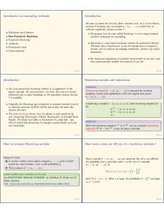
This presentation is focused on quaternary systems. However, it is difficult and in most cases impossible, to follow cooling and heating paths in four component systems. For example consider the four component diagram in the next slide. Note that each face of the equilateral tetrahedron is a two dimensional ternary system (cooling/heating paths can be followed for each of the face systems). Four component system diagrams cannot be displayed in two dimensions in a manner that allows cooling/heating paths to be followed. Just as ternary systems are made up of a series of composition (alkemade) triangles, four component systems are made up of a series of composition tetrahedra. Examples are presented in the next several slides. These diagrams can be used to predict what and how much of each phase is present in the solid condensed state. However, it is difficult to visualize in which tetrahedron a specific batch composition will be located. Therefore, A procedure is described in this presentation illustrating how to locate the specific tetrahedron that contains the batch composition and how to determine what and how much of each phase is present.
Source: INTRODUCTION TO PHASE EQUILBRIA IN CERAMIC SYSTEMS F.A. Hummel (Marcel Dekker, Inc.); originally taken from Levin, et al. by Hummel)
Note the abbreviations (as recommended
by the American Ceramic Society)
Quaternary Example
C4AF=4CaO:Al2O3:Fe2O3
More abbreviation examples:
3CaO.Al2O3=C3A=Ca3Al2O6
Quaternary Example
Try to visualize in which Tetrahedra this batch is located: 25% of C,M,A,Cr. Very difficult!
MgO.Al2O3=MA=MgAl2O4
Axes can be either mole% or weight%
Source: INTRODUCTION TO PHASE
EQUILBRIA IN CERAMIC SYSTEMS (F.A. Hummel (Marcel Dekker, Inc.)
Quaternary Example
Exploded view
Source: INTRODUCTION TO PHASE EQUILBRIA IN
CERAMIC SYSTEMS (F.A. Hummel (Marcel Dekker, Inc.)
Quaternary Example
The C-M-T-S system will be used to describe how to determine what phases are present and how much of each phase is present.
Source: PHASE DIAGRAMS FOR CERAMISTS Levin et al. (American Ceramic Society)
Source: INTRODUCTION TO PHASE EQUILBRIA IN
Quaternary Example
CERAMIC SYSTEMS (F.A. Hummel (Marcel Dekker, Inc.)
Very difficult to visualize where a specific batch is located!!
Quaternary Phase Systems!!
F=degrees of freedom (Gibbs phase rule), i.e. you can control F number of variables
PHASE RULE C=number of components
P= number of phases
Application of the phase rule to four component systems at 1 atmosphere: F = C - P + 2 and when Ptotal pressure = 1 atm F = 4 - P + 1 = 5 - P (Condensed Phase Rule)
The maximum number of phases that can coexist in a four component system is when F=0: P = 5-0= 5; 4 solid phases and 1 liquid phase. If a temperature is chosen less than the temperature required to solidify the liquid phase, e.g. a temperature where only solids exist; then P=4 (more discussion will be presented later)
EQUILIBRIUM DIAGRAMS
Procedure The question to be answered in this presentation is “how can we determine what (and how much) equilibrium condensed phases are present in a four component system for a specific batch composition?”
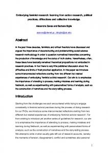
The following procedure is presented. To my knowledge this procedure was developed many years ago by Dr. Reinhardt Schuhmann while he was at Purdue University. He described the calculational technique while on sabbatical at the Colorado School of Mines in a graduate level class “Interpretation of Multicomponent Diagrams”. The CaO-MgO-TiO2-SnO2 system (abbreviated C-M-T-S) is used to demonstrate the procedure; the system is presented on the next slide. Note there are twelve possible tetrahedra in which the batch may be located.
Procedure T
MT2 MT2
S CT
MT MT
CT CT M2ST
MT M2T M2T
S
CT CT S CT
M2S
S CT
M2S
CS M2S
C3T2
M
CS
C3T2
CS
C3T2
M
CS
M M
C2S C2S
M C
Procedure
Determine the equations for planes between adjacent tetrahedra. (4 examples are presented, then refer to the summary table for the remainder of the equations)
Example 1:
o The plane between tetrahedron 1 (T-MT2-CT-S) and 2 (MT2CT-S-M2ST) is MT2-CT-S.
o Designate each plane component: MT2=J, CT=U, S=S o Set up a mass balance for each of the four components (C, M, T, S) distributed in the plane face phases
C=U; M=J, T=2J+U, S=S
o Solve the equation T=2J+U=2M+C o Set the equation = 0 (defines plane between tetrahedra 1 and 2)
2M+C-T=0
Procedure
Determine an equation for each plane between adjacent tetrahedra.
Example 2:
o The plane between tetrahedron 2 (MT2-M2ST-CT-S) and 3 (MT2-M2ST-CT-S) is MT2-CT-M2ST.
o Designate each plane component: MT2=J, M2ST=Z, CT=U o Set up a mass balance for each of the four components (C, M, T, S) as distributed through the plane face phases C=U; M=J+2Z, T=2J+Z+U, S=Z
o Solve the equation T=2J+Z+U=2*(M-2S)+S+C=2M-3S+C o Set the equation = 0 (defines plane between tetrahedra 2 and 3)
2M+C-3S-T=0
Procedure
Determine an equation for each plane between adjacent tetrahedra.
Example 3:
o The plane between tetrahedron 5 (MT-M2T-M2S-CT) and 7 (MM2T-M2S-CT) is M2T-CT-M2S.
o Designate each plane component: M2T=H, M2S=Y, CT=U o Set up a mass balance for each of the four components (C, M, T, S) as distributed through the plane face C=U; M=2H+2Y, T=H+U, S=Y
o Solve the equation M=2H+2Y=2*(T-C)+2S; M=2T-2C+2S o Set the equation = 0 (defines plane between tetrahedra 5 and 7)
2T+2S-2C-M=0
Procedure
Determine an equation for each plane between adjacent tetrahedra.
Example 4:
o The plane between tetrahedron 9 (M-M2S-CS-CT) and 10 (MCT-CS-C3T2) is M-CT-CS.
o Designate each plane component: M=M, CT=U, CS=W o Set up a mass balance for each of the four components (C, M, T, S) as distributed through the plane face
C=U+W; M=M, T=U, S=W Solve the equation C=T+S Set the equation = 0 (defines plane between tetrahedra 9 and 10)
T+S-C=0
Determine an equation for each plane between adjacent tetrahedra. (You should try to determine some of the equations as practice; results are shown in the following table)
Procedure
Results Equations for planes in the C-M-S-T system Tetrahedra Planes
Phases in Tetrahedra
Phases in Planes
Equation for planes
1
1-2
MT2-CT-S-T
MT2-CT-S
2M+C-T=0
2
2-3
MT2-M2ST-CT-S
MT2-CT-M2ST
2M+C-T-3S=0
2
2-6
MT2-M2ST-CT-S
M2ST-CT-S
2T-2C-M=0
3
3-4
MT-M2ST-MT2-CT
M2ST-CT-MT2
T+3S-C-2M=0
4
4-5
MT-M2S-M2ST-CT
M2ST-CT-MT
M-S+C-T=0
4
4-6
MT-M2S-M2ST-CT
M2ST-CT-M2T
2C+M-2T=0
5
5-7
MT-M2T-M2S-CT
M2T-CT-M2S
2T-2C+2S-M=0
6
6-8
M2S-M2ST-CT-S
M2S-CT-S
C-T=0
7
7-9
M-M2T-M2S-CT
M2S-CT-M
C-T=0
8
8-9
M2S-CT-CS-S
M2S-CT-CS
2T+2S-M+2C=0
9
9-10
M-M2S-CS-CT
M-CT-CS
T+S-C=0
10
10-11
M-CS-CT-C3T2
M-CS-C3T2
2S+3T-2C=0
11
11-12
M-CS-C2S-C3T2
M-C2S-C3T2
3T+4S-2C=0
12
M-C-C2S-C3T2
Procedure
EXAMPLE DETERMINATION
1) Determine the condensed phase makeup (in weight percent) for the following batch composition (values in weight percent)
20 %C, 24 %M, 50 %T, 6 %S Note that the quaternary system is plotted in mole percent Calculate the mole percent of each batch constituent
C=CaO: 20/56.087=0.356 moles; mole %=22.0 M=MgO: 24/40.305=0.595; mole %=36.8
T=TiO2: 50/79.867=0.626; mole %=38.7 S=SnO2: 6/150.71=0.040; mole %=2.5
Total moles=1.617
2) Determine in which tetrahedron this batch lies Next slide
Constituent
Atomic Weight
CaO MgO SnO2 TiO2
56.078 40.305 150.71 79.867
Phase CS C2S M2S M2ST CT C3T2 MT M2T MT2
206.788 262.866 231.32 311.187 135.945 327.968 120.172 160.477 200.039
Procedure Determine the direction of the batch composition from individual planes (examples are presented in the next slides) T
Diagram Source: Levin et al.
MT2
MT2 MT MT MT
M2T M2T
S
CT
M2ST
S
CT CT CT CT S
CT M2S
S CT
M2S
CS M2S
C3T2
M
CS
C3T2 M
CS
C3T2
CS
M M
C2S C2S
M C
Procedure 3a) Determine the direction of the batch composition from individual planes (example) Batch Check plane 1-2: C T
2M+C-T=0 = 2*36.8+22.0-38.7 =+
MT2 MT2 MT MT MT M2T M2T
M2ST
S
CT
S CT
M2S
CS M2S
C3T2
M
CS C3T2
M
CS
C3T2
CS M M
C2S C2S
M C
M
36.8
T
38.7
S
2.5
The equation solution is +
CT CT CT CT S
M2S
22.0
Note
S
CT
Mole %
To test the direction the batch is from the plane compare the signs of the pure constituents to the sign of the equation,
e.g. the direction toward pure T is -; so the batch is in a direction away from T (opposite direction from pure T). Check the equation to determine the other two directions: toward C is + so the batch is toward C; M is + so the batch is also toward M. So the conclusion for this test is that the batch is away from T and toward C and M. Therefore the batch is not in tetrahedron 1.
Procedure 3b) Determine the direction of the batch composition from individual planes (example) Batch Check plane 2-3: C T
2M+C-T-3S =0 = 2*36.8+22.0-38.73*2.5 =+
MT2 MT2 MT MT MT M2T M2T
M2ST
S
CT
S CT
M2S
CS M2S
C3T2
M
CS C3T2
M
CS
C3T2
CS M M
C2S C2S
M C
M
36.8
T
38.7
S
2.5
The equation solution is +
CT CT CT CT S
M2S
22.0
Note
S
CT
Mole %
To test the direction the batch is from the plane compare the signs of the constituents to the sign of the equation, e.g. the direction toward pure T is -; so the batch is in a direction away from T. The direction is also away from pure S and toward pure M and pure C. So the conclusion for this test is that the batch is away from T and S and toward C and M. Therefore, the batch may not be in tetrahedron 2. To be sure you need to test the plane 2-6 in tetrahedron 2 (next slide).
Procedure 3c) Determine the direction of the batch composition from individual planes (example) Check plane 2-6:
T
2T-2C-M=0 = 2*38.7-2*22.0-36.8 =-
MT2 MT2 MT MT MT M2T M2T
S
CT
M2ST
CT CT CT CT S CT
M2S
CS C3T2
M
CS C3T2
M
CS
C3T2
CS M M
C
22.0
M
36.8
T
38.7
S
2.5
The equation solution is -
CT
M2S
Mole %
Note
S
S M2S
Batch
C2S C2S
M C
To test the direction the batch is from the plane compare the signs of the constituents to the sign of the equation, e.g. the direction toward pure T is + and the equation is -; so the batch is in a direction away from pure T but toward pure C and pure M. So the conclusion for this test is that the batch is away from T and is toward C and M. This means the batch cannot be in tetrahedron 2. The 3 planes (1-2, 2-3 and 2-6) have been tested and the batch is outside 2.
Procedure 3d) Determine the direction of the batch composition from individual planes (example) Batch Check plane 3-4: T
MT2
MT M2T M2T
S
CT
MT MT M2ST
CT CT CT CT S CT
M2S
CS C3T2
M
CS C3T2
M
CS
C3T2
CS M M
M
36.8
= 22+2*36.8-3*2.5-38.7
T
38.7
=
S
2.5
+
The equation solution is +
CT
M2S
22.0
Note
S
S M2S
C
C+2M-3S-T=0
MT2
Mole %
C2S C2S
M C
The direction toward pure T is - and the equation is +; so the batch is in a direction away from the T but toward pure C and M. So the conclusion for this test is that the batch is away from T and is toward C and M. This means the batch cannot be in tetrahedron 3. Both planes (2-3 and 3-4) have been tested and the batch is outside 3.
Procedure 3e) Determine the direction of the batch composition from individual planes (example) Batch Check plane 4-6: T
2C+M-2T=0 = 2*22+36.8-2*38.7 =
MT2 MT2 MT MT MT M2T M2T
S
CT
M2ST
CT CT CT CT S CT
M2S
CS C3T2
M
CS C3T2
M
CS
C3T2
CS M M
22.0
M
36.8
T
38.7
S
2.5
The equation solution is +
CT
M2S
C
Note
S
S M2S
+
Mole %
C2S C2S
M C
The direction toward C and M is + and the equation is +; so the batch is in a direction toward pure C and pure M. T is – so the batch is away from pure T. So the conclusion for this test is that the batch is toward C and M but away from T. To be sure the batch is not in tetrahedron 4 you need to check the plane 4-5 (next slide).
Procedure 3f) Determine the direction of the batch composition from individual planes (example) Batch
T
Check plane 4-5: M+C-T-S=0
MT2
= 36.8+22-38.7-2.5=
MT2
CT
MT MT MT M2T M2T
S
M2ST
S
CT
S CT
M2S
CS M2S
C3T2
M
CS C3T2
M
CS
C3T2
CS M M
C2S C2S
M C
C
22.0
M
36.8
T
38.7
S
2.5
Note
CT CT CT CT S
M2S
+
Mole %
The equation solution is + The direction toward C and M is + and the equation is +; so the batch is in a direction toward C and M. T and S are – so the batch is away from T and S. So the conclusion for this test is that the batch is toward C and M. All planes in tetrahedron 4 have been tested (3-4, 4-5, and 4-6) and the batch is not in that tetrahedron. So we have eliminated tetrahedra 1, 2, 3, and 4.
Procedure 3g) Determine the direction of the batch composition from individual planes (example) Batch
T
Check plane 5-7: 2T-2C+2S-M=0= 2*38.7-
MT2
2*22+2*2.5-36.8 =
MT2
MT M2T M2T
M2ST
S
CT
S CT
M2S
CS M2S
C3T2
M
CS C3T2
M
CS
C3T2
CS M M
22.0
M
36.8
T
38.7
S
2.5
Note
CT CT CT CT S
M2S
C
S
CT
MT MT
+
Mole %
C2S C2S
M C
The equation solution is slightly + The direction toward pure M is - and
the equation is +; so the batch is in a direction away from M. T and S are + so the batch is toward pure T and pure S. So the conclusion for this test is that the batch is away from M and toward T and S. All planes in tetrahedron 5 have been tested (4-5 and 5-7) and the batch is in tetrahedron
5.
Procedure 3h) Determine the direction of the batch composition from individual planes (example) Batch C
22.0
The batch is in
M
36.8
tetrahedron
T
38.7
S
2.5
T
MT2 MT2 MT MT MT M2T M2T
S
CT
M2ST
CT CT CT CT
Tetrahedron 5 has 2 internal face planes:
CT
S CT
M2S
CS M2S
C3T2
M
CS
C3T2 M
CS
C3T2
CS M M
5.
Summary:
S
S M2S
Mole %
C2S C2S
M C
Plane 4-5. The batch is away from T and S and toward C and M. That checks that the batch must be away from 4-5. Plane 5-7. The batch is toward T and away from C and M. That checks that the batch must be within tetrahedron 5. What next?
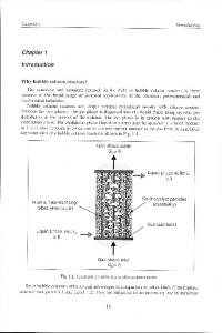
4a) Determine the batch makeup in weight percent T
The final equilibrium phases are given by the vertices of tetrahedron 5:
MT2
MT MT MT M2T M2T
M2ST M2S
M M M
R S S
CT CT
CS
C3T2
M
M
S
M2S M2S
MT+M2T+M2S+CT
S
CT CT CT CT CT
C3T2
CS CS
C3T2
CS C2S C2S C
H
MT2
Y
U
Solution (do a mass balance distribution of each constituent in the compounds)
Batch
Molex
C
0.356
M
0.595
T
0.626
S
0.04
C=0.356=U M=0.595=R+2H+2Y=R+2H+2*0.04 T=0.626=R+H+U=R+2H+0.356 S=0.04=Y Solve for each constituent phase (moles and mole%) CT=U=0.356 moles, mole%=0.356/0.666*100=53.4 MT=R=0.025 moles, mole%=3.8 M2T=H=0.245 moles, mole% =36.8 M2S=Y=0.04 moles, mole%=6.0
4b) Determine the batch makeup in weight percent T
The final equilibrium phases are given by the vertices of tetrahedron 5:
MT2
MT MT M2ST
MT M2T M2T
M2S
S
R S S
CT CT
M2S M2S
CS
C3T2
M
C3T2
M M M M CaO MgO SnO2 TiO2
Constituent
Atomic Weight 56.078 40.305 150.71 79.867
Phase CS C2S M2S M2ST CT C3T2 MT M2T MT2
MT+M2T+M2S+CT
S
CT CT CT CT CT
206.788 262.866 231.32 311.187 135.945 327.968 120.172 160.477 200.039
Y
U
Solve for each constituent phase (moles and mole%)
CT=U=0.356, mole%=0.356/0.666*100=53.4 MT=R=0.025, mole%=3.8
CS CS
C3T2
H
MT2
CS C2S C2S
M2T=H=0.245, mole% =36.8 M2S=Y=0.04, mole%=6.0
C
Solve for each constituent phase (grams and weight%) CT=0.356 moles*135.945 gm/mole=48.40 gms, wt%=48.4 MT=0.025 moles*120.172 gm/mole=3.00 gms, wt%=3.0 M2T=0.245 moles*160.477 gm/mole=39.32 gms, wt% =39.3 M2S=0.040 moles*231.32 gm/mole=9.25 gms, wt%=9.2
Final Solution
See if you can find the equilibrium phases for the following batch
PERSONAL EXAMPLE DETERMINATION
Determine the condensed phase makeup (in weight percent) for the following batch composition (values in weight percent) 15 %C, 35 %M, 40 %T, 10 %S T
MT2 MT2 MT MT MT M2T M2T
M2ST M2S
S S
CT CT
CS
C3T2
M M M M
GOOD LUCK!!
S
M2S M2S
M
S
CT CT CT CT CT
C3T2
CS CS
C3T2
CS C2S C2S C
If you would like more practice
PERSONAL EXAMPLE DETERMINATION
Determine the equations for planes between tetrahedra: J and L; L and F; L and K. Is the following batch (mole %) in tetrahedron L?? M=60%, A=5%, S=25%, Z=10% Source: Levin et al.
If you would like more practice
SUMMARY This presentation has been focused on quaternary condensed phase systems. A procedure has been presented that allows the user to determine in which tetrahedron a specific batch composition lies. This information allows the user to predict the phase makeup and the relative amounts of each phase present under equilibrium solid state conditions. The presented procedure was developed by Dr. Reinhardt Schuhmann, Jr and is just one example of the great contributions he made to the extractive pyrometallurgy and ceramic industries. Dr. Schuhmann was co-inventor of the Queneau-Schuhmann-Lurgi (QSL) continuous smelting process and was a long time member of the prestigious National Academy of Engineering.