Inversion-Based Hardware Gaussian Random Number Generator: A Case Study of Function Evaluation via Hierarchical Segmentation Dong-U Lee #1 , Ray C.C. Cheung ∗2 , John D. Villasenor #3 , Wayne Luk ∗4 #
Electrical Engineering Department, University of California Los Angeles, CA 90095, USA 1 3
∗
[email protected] [email protected]
Department of Computing, Imperial College London London, SW7 2BZ, UK 2
[email protected] [email protected]
4
I. I NTRODUCTION The evaluation of functions commonly occurs in numerous applications including communications, computer graphics, signal processing, and Monte Carlo simulations. In this paper, we examine hardware-based evaluation of the inverse Gaussian cumulative distribution function (IGCDF) required for the inversion method [1]. The inversion method is commonly used for generating random samples from arbitrary distributions. It is based on the observation that a random sample y with the cumulative distribution function (CDF) F can be generated by y = F −1 (x), where x is a uniform random variate between zero and one. Although F can be the CDF of any distribution, we consider the Gaussian distribution case with mean of zero and variance of one. The availability of Gaussian random numbers is essential to many simulation applications including channel code evaluation, molecular dynamics simulation, and financial modeling. Due to recent advances in field-programmable technology, hardware-based simulations attract increasing attention due to their huge performance advantages over traditional softwarebased methods. Transferring software-generated Gaussian samples to the hardware device is highly inefficient and can be a performance bottleneck, hence it is desirable to have a Gaussian random number generator (GRNG) on the hardware
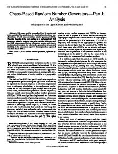
y = |F−1(x/2)|
y = F−1(x) 6
6
3 0
y
y
Abstract— We present the design and implementation of a Gaussian random number generator (GRNG) via hierarchical segmentation. Gaussian samples are generated using the inversion method, which involves the evaluation of the inverse Gaussian cumulative distribution function (IGCDF). The IGCDF is highly non-linear and is evaluated via piecewise polynomial approximations (splines) with a hierarchical segmentation scheme that involves uniform splines and splines with size varying by powers of two. This segmentation approach adapts the spline sizes according to the non-linearity of the function, allowing efficient evaluation of the IGCDF. Bit-widths of the fixed-point polynomial coefficients and arithmetic operators are optimized in an analytical manner to guarantee a precision accurate to one unit in the last place. Our architecture generates 16-bit Gaussian samples accurate to 8.2σ (standard deviations). A pipelined implementation on a Xilinx Virtex-4 XC4LX100-12 FPGA yields 371 MHz and occupies 543 slices, 2 block RAMs, and 2 DSP slices, generating one sample every clock cycle.
3
−3 −6 0
0.5 x
(a) y = F −1 (x)
1
0
0
0.5 x
1
(b) y = |F −1 (x/2)|
Fig. 1. Plot of (a) the inverse Gaussian CDF and (b) the actual curve for approximation over 2−32 ≤ x ≤ 1 − 2−32 .
device itself. In GRNGs, the quality of the Gaussian samples plays a key factor, since deviations from the ideal distribution can degrade simulation results and lead to incorrect conclusions. Attention needs to be paid to the samples that lie at the tails of the Gaussian probability density function (PDF), i.e., samples that lie multiples of σ (standard deviations) away. Although these samples occur relatively rarely, they are important because they can cause events of high interest. As depicted in Fig. 1(a), the IGCDF is highly non-linear due to its singularities at x = 0 and x = 1, making it difficult to accurately approximate. Very few contributions exist in the literature concerning hardware implementations of the inversion method. Chen et al. [2] employ a lookup table that has the advantage of being very simple, but has the disadvantage of memory requirements that increase exponentially with the number of bits at the input x. For example, for a 16-bit input / 16-bit output lookup table, a table size of 1 mega byte is needed. McCollum et al. [3] evaluate the IGCDF via linear interpolation, with equally-spaced data points. Their implementation leads to a large table size of 262 kilo bytes. In contrast to the above papers, we use nonuniformly sized splines combined with formal error analysis to achieve highly accurate Gaussian samples with very low memory requirements: our implementation involves less than 1 kilo byte (Section IV-B). A comprehensive discussion on other hardware GRNGs can be found in [4]. The key contributions of this paper include: • applying hierarchical segmentation for producing a hard-
ware GRNG architecture based on the inversion method; • accurate error analysis and bit-width optimization leading to a guaranteed worst-case error bound of 1 unit in the last place (ulp); • hardware realizations of the proposed architecture targeting advanced FPGAs. The rest of this paper is organized as follows. Section II shows an overview of the inversion-based GRNG design. Section III discusses hierarchical segmentation used for evaluating the IGCDF. Section IV describes bit-width optimization for the internal signals of the GRNG. Section V evaluates the GRNG and provides FPGA implementation results. Concluding remarks are given in Section VI. II. OVERVIEW For the design of inversion-based GRNG, the following parameters must be supplied: 1) GRNG periodicity (e.g. 1015 ); 2) Gaussian sample bit-width (e.g. 16 bits); 3) IGCDF approximation method (e.g. degree-1 splines, degree-2 splines, etc.). The first task is to perform hierarchical segmentation on the IGCDF curve, which partitions the curve into non-uniformly sized degree-d splines (piecewise polynomials). Since the IGCDF is symmetric around x = 0.5, one only needs to consider the absolute value of the first half of the function, i.e. y = |F −1 (x/2)| (Fig. 1(b)). Chebyshev coefficients [5] are used for the splines.The second task is bit-width optimization, which minimizes the bit-widths of the coefficients and operators while conforming to the Gaussian sample precision requirement. Finally, using the segmentation, coefficients, and bit-width information, VHDL code suitable for FPGA or ASIC implementation is generated. Fig. 2 depicts a high-level architecture of the inversionbased GRNG. A uniform random number generator (URNG) is used to provide the input x and a random sign for the Gaussian sample. The IGCDF evaluation unit approximates the function y = |F −1 (x/2)|, and the multiplexor selects the positive or the negated y. The bit-width of x, denoted by Bx , dictates the maximum attainable standard deviation maxσ of the GRNG. From Fig. 1(b) the maximum y occurs at the smallest non-zero value of x. Hence maxσ = |F −1 (2−Bx −1 )| = F −1 (1 − 2−Bx −1 ).
(1)
In order to meet the GRNG periodicity requirement, first, the periodicity of the URNG should be equal or greater than than the requested GRNG periodicity N . Second, the N samples generated should faithfully follow the true Gaussian distribution even at the far tails of the Gaussian PDF. Although in principle, the Gaussian PDF spans infinitely, for a given pool of N samples we can limit maxσ . More precisely, we select a maxσ such that the theoretical number of samples whose magnitude is greater than maxσ within the pool of N samples is kept below 0.5, i.e. N × (2 × F (−maxσ )) < 0.5
(2)
sign 1
Uniform Random Number Generator (URNG)
x Bx
Fig. 2.
Inverse Gaussian CDF (IGCDF) Evaluation Unit
y By
Negate
0 1
Gaussian Samples
High-level architecture of inversion-based GRNG.
where F is the Gaussian CDF. Substituting Eqn. (1) into Eqn. (2) we obtain the following relationship between Bx and N −1 −Bx −1 N × (2 × F (−F ))) < 0.5 ¡ 1 ¢ (1 − 2 ⇒ Bx > − log2 4N − 1.
(3)
In this work we consider the example of a GRNG with N = 1015 and 16-bit two’s complement fixed-point Gaussian samples, which is adequate even for the most ambitious simulation applications such as the evaluation of low-density parity check codes in very low bit error rates [6]. To meet the first requirement, using Eqn. (3) we find that the required Bx is 51 which results in maxσ = 8.1. However, in order to make a fair comparison with the Box-Muller based GRNG described in [4], we set Bx = 52 which results in maxσ = 8.2. Since the maximum Gaussian sample value is 8.2, five bits need to be allocated for the integer part to avoid overflow, and the remaining eleven bits are used for the fractional part. In order to generate high-quality Gaussian samples, we ensure that every sample is guaranteed to be faithfully rounded (accurate to 1 ulp). This means that samples will have an absolute maximum error of less than or equal to 2−11 compared to an ideal (infinitely precise) inversion-based GRNG. Although the example GRNG described here delivers 16-bit samples out to 8.2σ, the architecture itself is scalable for arbitrary multiples of σ and sample precisions. III. H IERARCHICAL S EGMENTATION A. Framework For implementing spline-based approximations in hardware, uniform segmentation, in which all segment lengths are equal, is the most common type of segmentation [7]. Although uniform segmentation has the advantage of simple coefficient indexing (by using the most significant bits), in contrast with non-uniform segmentation, it does not allow segment lengths to be customized to the non-linearity of the function. This can lead to impractically large tables for functions like y = |F −1 (x/2)| . The non-uniform segmentation we employ for efficient IGCDF approximation is called the hierarchical segmentation method [8]. In its general form, it utilizes a selection from a set of four segmentation schemes: U S, P 2SL , P 2SR , and P 2SLR . In U S, segments are uniformly sized. In P 2SL , the segment sizes increase by powers of two from the beginning of the input interval to the end of the interval, while in P 2SR the segment sizes decrease by powers of two from start to end. In P 2SLR , segment sizes increase by powers of two until the
y = |F−1(x/2)| 8 6 y
TABLE I S EGMENT RANGES IN BINARY REPRESENTATION FOR Bx = 8, P 2SL OUTER SEGMENTATION , AND Bx0 = 5. T HE FIVE BITS CORRESPONDING TO x0 ARE HIGHLIGHTED IN BOLD . T HE BITS TO THE LEFT OF THE VERTICAL PARTITION LINES CORRESPOND TO x ˆ0 .
4 2
Segment Address, j 0 1 2 3 4 5
Segment Range 0 0 0 0 0 1
0000| 0001| 001|0 01|00 1|000 |0000
0 0 0 0 0 0
0 0 0 0 0 0
0 0 0 0 0 0
∼ ∼ ∼ ∼ ∼ ∼
0 0 0 0 0 1
0000| 0001| 001|1 01|11 1|111 |1111
1 1 1 1 1 1
1 1 1 1 1 1
0 0
1 1 1 1 1 1
0.1
0.2
0.3
0.4
0.5 x
0.6
0.7
0.8
0.9
1
Fig. 3. Hierarchical segmentation applied to the IGCDF using degree-2 splines and ²req = 0.3 × 2−11 .
(the number of bits corresponding to x ˆ0 ) can be computed as follows midpoint of the interval and then decrease by powers of two until the end is reached. The hierarchical aspect arises because segmentation is applied twice. In the first pass, the entire interval is subdivided using one of the above four methods into several outer segments. In the second pass, each outer segment is further subdivided into inner segments using U S. The absolute value of the derivative at the interval endpoints is used to drive the choice of the outer segmentation scheme. High derivatives at one or both ends trigger use of P 2SL , P 2SR , or P 2SLR ; in the case where both derivatives are small then uniform segmentation is used. y = |F −1 (x/2)| has a high derivative near zero and hence P 2SL is chosen for the outer segmentation. The Bx bits of the input x are split into three partitions: x0 , x1 , and x2 . x0 and x1 are used to index the outer and inner segmentation respectively, while x2 is used for the polynomial arithmetic. The number of addressable segments si of the partition i is constrained as follows: si si
= =
2Bxi , if Λi = U S Bxi + 1, if Λi = P 2SL
(4) (5)
where Bxi denotes the bit-width and Λi denotes the segmentation of the partition i. Consider the case when Bx = 8, the outer segmentation is P 2SL , and Bx0 = 5. As illustrated in Table I, it is possible to construct a maximum of six segments. With the exception of the initial segments, the segment lengths increase by powers of two. The P 2SL segment address for a given x0 can be computed by ½ P 2SL addr =
Bx0 − LZD(x0 ), if M SB(x0 ) = 0 Bx0 , if M SB(x0 ) = 1
(6)
where LZD(x0 ) and M SB(x0 ) return the number of leading zeros and the most significant bit of x0 respectively. Let x ˆi denote the set of bits that remains constant within an outer segment (bits left to the vertical partition lines in Table I). For instance in Table I, when j = 3, then x ˆ0 = 001. The inner segmentation uses Bx1 bits immediately right of x ˆ0 . For the case when the outer segmentation is P 2SL , Bxˆ0
½ Bxˆ0 =
Bx0 , if P 2SL addr = 0 Bx0 − P 2SL addr + 1, otherwise.
(7)
B. Segmentation Algorithm Once the outer segmentation scheme is chosen via the derivative method, the next issue is the determination of Bx0 . If Bx0 is too small, there will be insufficient granularity in the outer segments to follow the local non-linearities of a function. On the other hand, if Bx0 is too large, there will be too many outer segments and the total number of segments will be unnecessarily large. The optimal Bx0 that result in the minimal number of segments can be found via linear search, where Bx0 is set to zero initially and is gradually incremented. The core of the segmentation algorithm requires four parameters: the input interval [a, b), the polynomial degree d to be used for the splines, and the desired maximum absolute error ²req at the output. For each segment in the outer segmentation, the Chebyshev coefficients for the approximating polynomial of appropriate degree are computed. If the approximation error ²max is too high, the number of segments in the inner segmentation is incremented by successive powers of two until the ²max of all inner segments are less than or equal to the required error ²req . This process is performed for all outer segments. Two tables are generated: ROM0 which is needed for ROM1 address computation, and ROM1 which holds the polynomial coefficients to each segment. ROM0 stores the Bx1 and the offset corresponding to each outer segment. The offset is simply the number of rows in ROM1 prior to the row in ROM1 corresponding to the current outer segment. Fig. 3 illustrates the segmentation when the algorithm is applied to the IGCDF using degree-2 splines with an error requirement of ²req = 0.3 × 2−11 . The black and grey vertical lines indicate the boundaries for the outer and inner segmentations. A total of 144 segments are required. 51 bits are allocated for Bx0 , which results in the minimal number of segments. C. Hardware Architecture Fig. 4 shows the architecture of the IGCDF evaluation unit for degree-2 splines. The P 2S unit performs the P 2SL
x
Address Decoding
x0
x1 B x0
x2 B x1
P2S unit
B x2
index B x1 offset 0 1 ROM0 ...
bit selection unit
Bx0
IV. B IT-W IDTH O PTIMIZATION
52
addr
Bx0
... s0-1
Polynomial Evaluation index 0 1 ...
Q
... M-1 B x~2
C2
A. Range Analysis C1
C0
ROM1
B C2 Q
B C1 B D2
The preceding section does not consider finite precision effects. However, for hardware implementations, it is desirable to minimize the bit-widths of the coefficients and operators for area and speed efficiency, while respecting the error constraint at the output signal. Two’s complement fixed-point arithmetic is assumed throughout. Given a signal x, its integer bitwidth (IB) is denoted by IBx and its fractional bit-width (F B) is denoted by F Bx , i.e. Bx = IBx + F Bx . IB controls the range, while F B controls the precision of a signal. The bit-width allocation problem is split into two stages: range analysis for determining the minimal IBs followed by precision analysis for determining the minimal F Bs required. For both analysis phases, we use an adaptation of the MiniBit technique [9].
Q
B C0
BD1 Q
B D0
To compute the dynamic range of a signal, the local minima/maxima and the minimum/maximum input values of each signal are examined. The local minima/maxima can be found by computing the roots of the derivative. Once the dynamic range has been found, the required IB can be computed trivially. Since splines are being used, the polynomial evaluation circuit needs to be shared among different sets of coefficients. The IB for each signal is found for every segment and stored in a vector. Since the signal needs to be wide enough to avoid overflow for the data with the largest dynamic range, the largest IB in the vector is used. B. Precision Analysis
Q
16
y Fig. 4. The IGCDF evaluation unit for degree-2 splines. The grey square boxes labeled “Q” perform quantization operations.
address and the Bxˆ0 computation (Eqn. (6) and Eqn. (7)). The bit selection unit selects the appropriate bits for x0 , x1 , and x2 from the input x in conjunction with ROM0. Two barrel shifters are present inside this unit, due to the variable natures of Bxˆ0 and Bx1 . The grey square boxes labeled “Q” perform quantization operations. Since x0 and x1 are implicitly known for a given segment, x2 is used instead of x for the polynomial arithmetic to reduce the size of the operators. x2 is scaled to occupy the range [0, 1), which in turn requires appropriate transformations on the Chebyshev coefficients [4]. Because the minimum sum of Bxˆ0 and Bx1 is 4 bits, the maximum Bx2 is 48 bits. x2 is quantized before it is supplied to the multipliers. This quantization step can potentially save hardware, since in this particular application, the output y is allowed to be significantly less precise than the input x2 .
The following three sources of error exist: (1) the inherent error ²∞ due to approximating the function with polynomials, (2) quantization error ²Q due to finite precision effects (i.e. roundoff errors due to quantization) incurred when evaluating the polynomials, and (3) the error of the final output rounding step, which can cause a maximum error of 0.5 ulp. In the worst case, ²∞ and ²Q will contribute additively, so to achieve faithful rounding, their sum must be less than 0.5 ulp. We allocate a maximum of 0.3 ulp for ²∞ and the rest for ²Q , which is found to provide a good balance between the two error sources. This is the reason why the IGCDF error requirement has been set to 0.3 × 2−11 in Section III-B. Quantization is usually performed in two modes: truncation which can cause a maximum error of 2−F B (1 ulp), and roundto-nearest which can cause a maximum error of 2−F B−1 (0.5 ulp). Round-to-nearest must be performed at the output signal y to achieve faithful rounding, but either rounding mode can be used for the internal signals. Since truncation results in better delay and area characteristics over round-to-nearest, it is used for the internal signals. Note that the polynomial coefficients are rounded to the nearest at compile-time. For the addition/subtraction z = x ± y, the error ²z at the output z is given by ²z
=
²x + ²y + 2−F Bz
(8)
TABLE II B IT- WIDTHS OBTAINED AFTER BIT- WIDTH OPTIMIZATION FOR THE DEGREE -2 CASE .
where 2−F Bz is the quantization error at z assuming that truncation is performed. Similarly, for the multiplication z = x × y, we get =
x²y + y²x + ²x ²y + 2−F Bz .
(9)
Note that ²z is at its maximum when x and y are at their maximum absolute values. The addition and multiplication error expressions in Eqn. (8) and Eqn. (9) are applied to every operator, and a constraint for achieving faithful rounding can be generated for the output signal. Consider the degree-2 polynomial evaluation circuitry in Fig. 4. Assuming max(|˜ x2 |) = 1, we derive the following error terms for the output and the internal signals: ²y
=
²D0 + 2−F BC0 −1 + 2−F By −1 + ²∞
(10)
²D0
=
²D1 + D1 2−F Bx + ²D1 2−F Bx + 2−F BD0
(11)
²D1
=
²D2 + 2−F BC1 −1 + 2−F BD1
(12)
²D2
=
2−F BC2 −1 + C2 2−F Bx + 2−F BC2 −1 2−F Bx + 2−F BD2 .
(13)
Note that the inherent approximation error ²∞ has been added to ²y . Combining Eqn. (10) ∼ Eqn. (13) and knowing that F By = 11, we can obtain the following constraint for faithfully rounded y: −12
2
≥
(2
−F BC2 −1
(1 + 2
−F Bx
−F Bx
) + C2 2
+ 2−F BD2 + 2−F BC1 −1 + 2−F BD1 )(1 + 2−F Bx ) + D1 2−F Bx + 2−F BD0 + 2−F BC0 −1 + ²∞ .
(14)
After applying hierarchical segmentation algorithm to the degree-2 case, we find that ²∞ = 1.4620×10⁻⁴ , max(|D1 |) = 1.9559×10⁻¹ , and max(|C2 |) = 3.8570×10⁻² . The inequality in Eqn. (14) leads to an optimization problem, where the goal is to find the smallest F B to each signal that satisfy the constraint. We address this problem using Adaptive Simulated Annealing (ASA) [10], which allows faster convergence times than traditional simulated annealing. In ASA, the user is required to supply a constraint function and a cost function. For the constraint function, error functions such as Eqn. (14) are supplied. For the cost function, we supply an FPGA area estimation model for each of the main components: memory, adders, and multipliers. Table II gives the IBs and the F Bs found by the range and precision analysis phases. A negative IB identifies the number of bit positions after the binary point that are always zero. As discussed in Section III-C, quantizing the input x ˜2 has made a notable impact; reducing its original bit-width of 49 bits to just 23 bits. The total width of the three coefficients is 12+15+21 = 48 bits and the number of segments have been found to be 144 in Section III-B. Therefore, the size of the table holding the polynomial coefficients (ROM1 in Fig. 3) is 48 × 144 = 6912 bits. The size of the segmentation information table ROM0 is found to be just 520 bits, resulting in a total memory requirement of 6912+520 = 7432 bits. This contrasts with the
Error [ulp]
²z
Signal
x ˜2
C2
C1
C0
D2
D1
B
23
12
15
21
16
15
22
(IB, F B)
(0,23)
(-3,15)
(-1,16)
(5,16)
(-3,19)
(-1,16)
(-1,23)
1 0.8 0.6 0.4 0.2 0 −0.2 −0.4 −0.6 −0.8 −1 0
0.1
0.2
0.3
0.4
0.5 x
0.6
0.7
0.8
D0
0.9
1
Fig. 5. Error plot of 216 randomly selected samples for degree-2 spline approximation.
large memory requirements of Chen et al. [2] and McCollum et al. [3] discussed in Section I. V. E VALUATION AND R ESULTS In order to test the accuracy of the Gaussian samples, we compare ten billion samples from this GRNG against the ones generated from a floating-point accuracy software-based IGCDF approximation. As anticipated, the ulp error of all samples are found to be less than 1 ulp. In addition, over 96% of the samples are observed to be accurate to 0.5 ulp (i.e. exactly rounded). Fig. 5 shows an ulp error plot of 216 randomly selected samples for degree-2 splines. The black curve indicates the inherent approximation error ²∞ , while the grey curve indicates the error with finite precision effects. Fig. 6 shows the PDF of the generated Gaussian samples for a population of one million samples between 7σ and 8.2σ. Even in such high σ regions, the GRNG faithfully follows the ideal Gaussian distribution. Statistical tests, such as the χ2 test or the Anderson-Darling test [11] are not necessary, since (a) we know that the derivation of the inversion-based GRNG algorithm itself is correct and (b) we generate the samples accurately within the 16-bit resolution. The FPGA implementations presented of this section are written in VHDL and are mapped on a Xilinx Virtex-4 XC4VLX100-12 device. Synplicity Synplify Pro 8.4 is used for synthesis, and Xilinx ISE 8.1.02i is used for placement and routing. The URNG in Fig. 2 is realized via two 32-bit Tausworthe URNGs [12]. The Tausworthe URNG combines three linear feedback shift register (LFSR) based URNGs to obtain improved statistical properties, over traditional LFSRs. It generates a 32-bit uniform random number per cycle, and has a large period of 288 (≈ 1025 ) which is significantly larger than our periodicity requirement N = 1015 . Fig. 7 explores the area variation of different degree spline approximation with
TABLE III I MPLEMENTATION RESULTS OF DEGREE -1 AND DEGREE -2 SPLINE GRNG S ON A X ILINX V IRTEX -4 XC4VLX100-12 FPGA.
−11
1
x 10
0.9 0.8
Method Slices Block RAMs DSP Slices Clock Speed [MHz] Samples / Cycle Million Samples / Sec Throughput / Slice
0.7 PDF(x)
0.6 0.5 0.4 0.3 0.2 0.1 0 7
7.2
7.4
7.6 x
7.8
8
2000
Degree−1 Degree−2 Degree−3
1800 Area [slices]
1600 1400 1200 1000 800 600 400 200 6
Fig. 7.
8
10
12 14 Precision [bits]
16
18
Degree-2 579 1 4 370 1 370 0.639
8.2
Fig. 6. PDF of the generated Gaussian samples for a population of one million samples between 7σ and 8.2σ. The black solid line indicates the ideal Gaussian PDF. 2200
Degree-1 543 2 2 371 1 371 0.683
20
Area comparisons of different degree spline approximations.
precision. The “precision” refers to the number of fractional bits of the Gaussian samples and Bx is kept constant at 52. In order to examine the tradeoffs of different degrees, designs are combinatorial and use slices only. For precisions below 12 bits, degree-1 is the most area efficient. For precisions between 12 and 16 bits, degree-2 is the most desirable, while for precisions above 16 bits, degree-3 is the most attractive. Since we are aiming for 11 bits of precision in this work, degree-1 or degree-2 splines are likely to be the best option. Table III summarizes implementation results of degree1 and degree-2 spline GRNGs on a Xilinx Virtex-4 XC4VLX100-12 FPGA. Both designs are deeply pipelined and can generate 16-bit samples accurate to 1 ulp at a maximum of 8.2σ. The designs have similar slice usage and clock speed, but exhibit different block RAM and DSP slice tradeoffs. The degree-1 implementation has a throughput of 371 million samples per second, which is more than 10 times faster than the fastest GRNG implementation reported on an Intel Pentium-4 3 GHz PC [4]. Higher throughputs can be obtained by placing multiple GRNGs on the same device. Implementing
the same specification of our inversion-based GRNG (8.2σ and 16-bit samples) with the direct table lookup approach by Chen et al. [2] would require an impractical lookup table size of 252 × 16 bits = 8 peta bytes. Similarly, the equallyspaced linear interpolation method by McCollum et al. [3] would lead to a large memory requirement of approximately 16 giga bytes, primarily due to the inefficiency of uniform segmentation when applied to the IGCDF curve. Table IV compares of our designs against three other GRNGs: the Box-Muller & central limit theorem design in Xilinx System Generator 7.1 [13], the Ziggurat design in [14], and the Box-Muller design in [4]. Note that the Xilinx design is based on Xilinx’s AWGN core 1.0 [15] which follows the architecture by Boutillon et al. [16]. In order to make the comparisons fair, all designs are implemented on a Xilinx Virtex-II XC2V4000-6 FPGA. To the best to our knowledge, the Box-Muller based design in [4] and the proposed inversionbased designs are the only GRNGs in the literature that can generate samples accurate to 1 ulp. The table indicates that our designs and the Box-Muller design in [4] have the best throughput/slice ratio, the maximum obtainable σ multiple, and the best sample quality. Although the inversion-based GRNGs exhibit half the throughput of [4], they occupy slightly over one-third of the FPGA resources of [4]. For applications that require just a single Gaussian sample per cycle, the design in [4] would be wasteful since it inherently generates two samples per cycle. Moreover, slight correlations exist between the two samples in the Box-Muller design. The inversion-based GRNGs do not suffer from such drawbacks. VI. C ONCLUSIONS We have presented a flexible GRNG architecture based on the inversion method. The highly non-linear IGCDF, the core of the inversion method, has been approximated via the hierarchical segmentation method. This segmentation approach adapts the spline sizes according to the behavior of the function, allowing efficient approximation of the IGCDF. Bitwidths of the coefficients and operators have been minimized in an analytical manner, resulting in area efficiency and 1 ulp accuracy for every Gaussian sample generated. A degree1 spline implementation on Xilinx Virtex-4 XC4LX100-12
TABLE IV C OMPARISONS OF DIFFERENT GRNG S IMPLEMENTED ON A X ILINX V IRTEX -2 XC2V4000-6 FPGA. “CLT” REFERS TO THE CENTRAL LIMIT THEOREM .
Design Method Slices Block RAMs Block Multipliers Clock Speed [MHz] Samples / Cycle Million Samples / Sec Throughput / Slice maxσ Sample Quality Sample Bit-Width ulp Accuracy Guarantee
Xilinx [13] Box-Muller & CLT 653 4 8 168 1 168 0.26 4.8 Low 16 No
Zhang [14] Ziggurat 891 4 2 170 0.993 168 0.19 N/A High 32 No
FPGA occupies 543 slices, 2 block RAMs, and 2 DSP slices. It runs at 371 MHz, generating a sample every clock cycle. Current and future work includes extending the inverse CDF evaluation approach across other distributions and exploring the use of RNGs in various applications. ACKNOWLEDGMENTS The authors thank Hyungjin Kim and David Choi for their assistance. The support of the U.S. Office of Naval Research (Contract number N00014-06-1-0253), the U.S. National Science Foundation (Grant number CCR-0120778 and CCF0541453), the Croucher Foundation, Xilinx Inc., and the U.K. Engineering and Physical Sciences Research Council (Grant number EP/C509625/1, EP/C549481/1, and GR/R 31409) is gratefully acknowledged. R EFERENCES [1] W. H¨ormann and J. Leydold, “Continuous random variate generation by fast numerical inversion,” ACM Trans. Modeling and Computer Simulation, vol. 13, no. 4, pp. 347–362, Oct 2003. [2] J. Chen, J. Moon, and K. Bazargan, “Reconfigurable readback-signal generator based on a field-programmable gate array,” IEEE Trans. Magnetics, vol. 40, no. 3, pp. 1744–1750, May 2004. [3] J. McCollum, J. Lancaster, D. Bouldin, and G. Peterson, “Hardware acceleration of pseudo-random number generation for simulation applications,” in Proc. IEEE Southeastern Symp. System Theory, 2003, pp. 299–303. [4] D. Lee, J. Villasenor, W. Luk, and P. Leong, “A hardware Gaussian noise generator using the Box-Muller method and its error analysis,” IEEE Trans. Computers, vol. 55, no. 6, pp. 659–671, Jun 2006.
Lee [4] Box-Muller 1528 3 12 233 2 466 0.30 8.2 Very High 16 Yes
Proposed Inversion (Degree-1) Inversion (Degree-2) 548 585 2 1 2 4 232 231 1 1 232 231 0.42 0.39 8.2 8.2 Very High Very High 16 16 Yes Yes
[5] J. Muller, Elementary Functions: Algorithms and Implementation, 2nd ed. Birkhauser, 2006. [6] L. Sun, H. Song, Z. Keirn, and B. Vijaya Kumar, “Field programmable gate array (FPGA) for iterative code evaluation,” IEEE Trans. Magnetics, vol. 42, no. 2, pp. 226–231, Feb 2006. [7] J. Detrey and F. de Dinechin, “A parameterized floating-point exponential function for FPGAs,” in Proc. IEEE Int’l Conf. Field-Programmable Technology, 2005, pp. 27–34. [8] D. Lee, W. Luk, J. Villasenor, and P. Cheung, “Hierarchical segmentation schemes for function evaluation,” in Proc. IEEE Int’l Conf. FieldProgrammable Technology, 2003, pp. 92–99. [9] D. Lee, A. Abdul Gaffar, O. Mencer, and W. Luk, “MiniBit: bitwidth optimization via affine arithmetic,” in Proc. ACM/IEEE Design Automation Conf., 2005, pp. 837–840. [10] L. Ingber, Adaptive Simulated Annealing (ASA) 25.15, 2004, http://www.ingber.com/#ASA. [11] D. Knuth, Seminumerical algorithms, 3rd ed., ser. The Art of Computer Programming. Addison-Wesley, 1997, vol. 2. [12] P. L’Ecuyer, “Maximally equidistributed combined Tausworthe generators,” Mathematics of Computation, vol. 65, no. 213, pp. 203–213, Jan 1996. [13] Xilinx System Generator User Guide v7.1, Xilinx Inc., 2005, http://www.xilinx.com. [14] G. Zhang, P. Leong, D. Lee, J. Villasenor, R. Cheung, and W. Luk, “Ziggurat-based hardware Gaussian random number generator,” in Proc. IEEE Int’l Conf. Field-Programmable Logic and its Applications, 2005, pp. 275–280. [15] Additive White Gaussian Noise (AWGN) Core v1.0, Xilinx Inc., 2002, http://www.xilinx.com. [16] E. Boutillon, J. Danger, and A. Gazel, “Design of high speed AWGN communication channel emulator,” Analog Integrated Circuits and Signal Processing, vol. 34, no. 2, pp. 133–142, Feb 2003.