This edition applies to Internet Protocol Version 6 (IPv6) implementation with
Microsoft Windows Server 2008,. Red Hat Enterprise Linux 5.5, IBM AIX 5L V5.3,
...
Front cover
IPv6 Introduction and Configuration
Introduction to IPv6
IPv6 addressing and packet format
IPv6 host configuration
Sangam Racherla Jason Daniel
ibm.com/redbooks
Redpaper
International Technical Support Organization IPv6 Introduction and Configuration May 2012
REDP-4776-00
Note: Before using this information and the product it supports, read the information in “Notices” on page v.
First Edition (May 2012) This edition applies to Internet Protocol Version 6 (IPv6) implementation with Microsoft Windows Server 2008, Red Hat Enterprise Linux 5.5, IBM AIX 5L V5.3, and VMware vSphere ESXi 5.0. © Copyright International Business Machines Corporation 2012. All rights reserved. Note to U.S. Government Users Restricted Rights -- Use, duplication or disclosure restricted by GSA ADP Schedule Contract with IBM Corp.
Contents Notices . . . . . . . . . . . . . . . . . . . . . . . . . . . . . . . . . . . . . . . . . . . . . . . . . . . . . . . . . . . . . . . . . .v Trademarks . . . . . . . . . . . . . . . . . . . . . . . . . . . . . . . . . . . . . . . . . . . . . . . . . . . . . . . . . . . . . . vi Preface . . . . . . . . . . . . . . . . . . . . . . . . . . . . . . . . . . . . . . . . . . . . . . . . . . . . . . . . . . . . . . . . . vii The team who wrote this paper . . . . . . . . . . . . . . . . . . . . . . . . . . . . . . . . . . . . . . . . . . . . . . . vii Now you can become a published author, too! . . . . . . . . . . . . . . . . . . . . . . . . . . . . . . . . . . viii Comments welcome. . . . . . . . . . . . . . . . . . . . . . . . . . . . . . . . . . . . . . . . . . . . . . . . . . . . . . . viii Stay connected to IBM Redbooks . . . . . . . . . . . . . . . . . . . . . . . . . . . . . . . . . . . . . . . . . . . . viii Chapter 1. Internet Protocol version 6 . . . . . . . . . . . . . . . . . . . . . . . . . . . . . . . . . . . . . . . 1 1.1 Introduction to IPv6 . . . . . . . . . . . . . . . . . . . . . . . . . . . . . . . . . . . . . . . . . . . . . . . . . . . . . 2 1.1.1 IPv6 features overview . . . . . . . . . . . . . . . . . . . . . . . . . . . . . . . . . . . . . . . . . . . . . . 3 1.2 IPv6 header format . . . . . . . . . . . . . . . . . . . . . . . . . . . . . . . . . . . . . . . . . . . . . . . . . . . . . 3 1.2.1 Extension headers . . . . . . . . . . . . . . . . . . . . . . . . . . . . . . . . . . . . . . . . . . . . . . . . . 5 1.2.2 IPv6 addressing . . . . . . . . . . . . . . . . . . . . . . . . . . . . . . . . . . . . . . . . . . . . . . . . . . 10 1.2.3 Traffic class . . . . . . . . . . . . . . . . . . . . . . . . . . . . . . . . . . . . . . . . . . . . . . . . . . . . . . 14 1.2.4 Flow labels . . . . . . . . . . . . . . . . . . . . . . . . . . . . . . . . . . . . . . . . . . . . . . . . . . . . . . 15 1.2.5 IPv6 security . . . . . . . . . . . . . . . . . . . . . . . . . . . . . . . . . . . . . . . . . . . . . . . . . . . . . 15 1.2.6 Packet sizes . . . . . . . . . . . . . . . . . . . . . . . . . . . . . . . . . . . . . . . . . . . . . . . . . . . . . 18 1.3 DNS in IPv6. . . . . . . . . . . . . . . . . . . . . . . . . . . . . . . . . . . . . . . . . . . . . . . . . . . . . . . . . . 19 1.3.1 Format of IPv6 resource records. . . . . . . . . . . . . . . . . . . . . . . . . . . . . . . . . . . . . . 20 1.4 DHCP in IPv6 . . . . . . . . . . . . . . . . . . . . . . . . . . . . . . . . . . . . . . . . . . . . . . . . . . . . . . . . 22 1.4.1 DHCPv6 messages. . . . . . . . . . . . . . . . . . . . . . . . . . . . . . . . . . . . . . . . . . . . . . . . 23 1.5 IPv6 mobility support . . . . . . . . . . . . . . . . . . . . . . . . . . . . . . . . . . . . . . . . . . . . . . . . . . . 23 Chapter 2. Internet Control Message Protocol version 6 . . . . . . . . . . . . . . . . . . . . . . . 2.1 ICMPv6 messages . . . . . . . . . . . . . . . . . . . . . . . . . . . . . . . . . . . . . . . . . . . . . . . . . . . . 2.1.1 Neighbor discovery . . . . . . . . . . . . . . . . . . . . . . . . . . . . . . . . . . . . . . . . . . . . . . . . 2.1.2 Multicast Listener Discovery . . . . . . . . . . . . . . . . . . . . . . . . . . . . . . . . . . . . . . . . .
27 28 29 37
Chapter 3. Internet Protocol version 6 host configuration . . . . . . . . . . . . . . . . . . . . . . 3.1 Network topology . . . . . . . . . . . . . . . . . . . . . . . . . . . . . . . . . . . . . . . . . . . . . . . . . . . . . 3.2 Microsoft Windows Server 2008 . . . . . . . . . . . . . . . . . . . . . . . . . . . . . . . . . . . . . . . . . . 3.2.1 Stateless auto-configuration or DHCP . . . . . . . . . . . . . . . . . . . . . . . . . . . . . . . . . 3.2.2 Static addressing . . . . . . . . . . . . . . . . . . . . . . . . . . . . . . . . . . . . . . . . . . . . . . . . . 3.3 Red Hat Enterprise Linux (RHEL) 5.5 . . . . . . . . . . . . . . . . . . . . . . . . . . . . . . . . . . . . . . 3.3.1 Stateless auto-configuration or DHCP . . . . . . . . . . . . . . . . . . . . . . . . . . . . . . . . . 3.3.2 Static address . . . . . . . . . . . . . . . . . . . . . . . . . . . . . . . . . . . . . . . . . . . . . . . . . . . . 3.4 IBM AIX 5L V5300-006 . . . . . . . . . . . . . . . . . . . . . . . . . . . . . . . . . . . . . . . . . . . . . . . . . 3.4.1 Stateless auto-configuration or DHCP . . . . . . . . . . . . . . . . . . . . . . . . . . . . . . . . . 3.4.2 Static address . . . . . . . . . . . . . . . . . . . . . . . . . . . . . . . . . . . . . . . . . . . . . . . . . . . . 3.5 VMware vSphere ESXi 5.0 . . . . . . . . . . . . . . . . . . . . . . . . . . . . . . . . . . . . . . . . . . . . . . 3.5.1 Enabling IPv6 . . . . . . . . . . . . . . . . . . . . . . . . . . . . . . . . . . . . . . . . . . . . . . . . . . . . 3.5.2 Configuring IPv6 on a standard virtual switch . . . . . . . . . . . . . . . . . . . . . . . . . . . . 3.5.3 Static address . . . . . . . . . . . . . . . . . . . . . . . . . . . . . . . . . . . . . . . . . . . . . . . . . . . .
41 42 43 44 48 53 54 57 61 61 64 70 71 71 75
Related publications . . . . . . . . . . . . . . . . . . . . . . . . . . . . . . . . . . . . . . . . . . . . . . . . . . . . . 79 IBM Redbooks . . . . . . . . . . . . . . . . . . . . . . . . . . . . . . . . . . . . . . . . . . . . . . . . . . . . . . . . . . . 79 Other publications . . . . . . . . . . . . . . . . . . . . . . . . . . . . . . . . . . . . . . . . . . . . . . . . . . . . . . . . 79
© Copyright IBM Corp. 2012. All rights reserved.
iii
Online resources . . . . . . . . . . . . . . . . . . . . . . . . . . . . . . . . . . . . . . . . . . . . . . . . . . . . . . . . . 81 Help from IBM . . . . . . . . . . . . . . . . . . . . . . . . . . . . . . . . . . . . . . . . . . . . . . . . . . . . . . . . . . . 81
iv
IPv6 Introduction and Configuration
Notices This information was developed for products and services offered in the U.S.A. IBM may not offer the products, services, or features discussed in this document in other countries. Consult your local IBM representative for information on the products and services currently available in your area. Any reference to an IBM product, program, or service is not intended to state or imply that only that IBM product, program, or service may be used. Any functionally equivalent product, program, or service that does not infringe any IBM intellectual property right may be used instead. However, it is the user's responsibility to evaluate and verify the operation of any non-IBM product, program, or service. IBM may have patents or pending patent applications covering subject matter described in this document. The furnishing of this document does not give you any license to these patents. You can send license inquiries, in writing, to: IBM Director of Licensing, IBM Corporation, North Castle Drive, Armonk, NY 10504-1785 U.S.A. The following paragraph does not apply to the United Kingdom or any other country where such provisions are inconsistent with local law: INTERNATIONAL BUSINESS MACHINES CORPORATION PROVIDES THIS PUBLICATION "AS IS" WITHOUT WARRANTY OF ANY KIND, EITHER EXPRESS OR IMPLIED, INCLUDING, BUT NOT LIMITED TO, THE IMPLIED WARRANTIES OF NON-INFRINGEMENT, MERCHANTABILITY OR FITNESS FOR A PARTICULAR PURPOSE. Some states do not allow disclaimer of express or implied warranties in certain transactions, therefore, this statement may not apply to you. This information could include technical inaccuracies or typographical errors. Changes are periodically made to the information herein; these changes will be incorporated in new editions of the publication. IBM may make improvements and/or changes in the product(s) and/or the program(s) described in this publication at any time without notice. Any references in this information to non-IBM websites are provided for convenience only and do not in any manner serve as an endorsement of those websites. The materials at those websites are not part of the materials for this IBM product and use of those websites is at your own risk. IBM may use or distribute any of the information you supply in any way it believes appropriate without incurring any obligation to you. Information concerning non-IBM products was obtained from the suppliers of those products, their published announcements or other publicly available sources. IBM has not tested those products and cannot confirm the accuracy of performance, compatibility or any other claims related to non-IBM products. Questions on the capabilities of non-IBM products should be addressed to the suppliers of those products. This information contains examples of data and reports used in daily business operations. To illustrate them as completely as possible, the examples include the names of individuals, companies, brands, and products. All of these names are fictitious and any similarity to the names and addresses used by an actual business enterprise is entirely coincidental. COPYRIGHT LICENSE: This information contains sample application programs in source language, which illustrate programming techniques on various operating platforms. You may copy, modify, and distribute these sample programs in any form without payment to IBM, for the purposes of developing, using, marketing or distributing application programs conforming to the application programming interface for the operating platform for which the sample programs are written. These examples have not been thoroughly tested under all conditions. IBM, therefore, cannot guarantee or imply reliability, serviceability, or function of these programs.
© Copyright IBM Corp. 2012. All rights reserved.
v
Trademarks IBM, the IBM logo, and ibm.com are trademarks or registered trademarks of International Business Machines Corporation in the United States, other countries, or both. These and other IBM trademarked terms are marked on their first occurrence in this information with the appropriate symbol (® or ™), indicating US registered or common law trademarks owned by IBM at the time this information was published. Such trademarks may also be registered or common law trademarks in other countries. A current list of IBM trademarks is available on the Web at http://www.ibm.com/legal/copytrade.shtml The following terms are trademarks of the International Business Machines Corporation in the United States, other countries, or both: AIX 5L™ AIX® IBM®
Redbooks® Redpaper™ Redbooks (logo)
System p® System x® ®
The following terms are trademarks of other companies: Linux is a trademark of Linus Torvalds in the United States, other countries, or both. Microsoft, Windows, and the Windows logo are trademarks of Microsoft Corporation in the United States, other countries, or both. Intel, Intel logo, Intel Inside, Intel Inside logo, Intel Centrino, Intel Centrino logo, Celeron, Intel Xeon, Intel SpeedStep, Itanium, and Pentium are trademarks or registered trademarks of Intel Corporation or its subsidiaries in the United States and other countries. Other company, product, or service names may be trademarks or service marks of others.
vi
IPv6 Introduction and Configuration
Preface Anyone who is involved with information technology knows that the Internet is running out of IP addresses. The last block of Internet Protocol version 4 (IPv4) addresses was allocated in 2011. Internet Protocol version 6 (IPv6) is the replacement for IPv4, and it is designed to address the depletion of IP addresses and change the way traffic is managed. This IBM® Redpaper™ publication describes the concepts and architecture of IPv6 with a focus on:
An overview of IPv6 features An examination of the IPv6 packet format An explanation of additional IPv6 functions A review of IPv6 mobility applications
This paper provides an introduction to Internet Control Message Protocol (ICMP) and describes the functions of ICMP in an IPv6 network. This paper also provides IPv6 configuration steps for the following clients:
Microsoft Windows Red Hat Enterprise Linux IBM AIX® VMware vSphere ESXi 5.0
After understanding the basics of IPv6 concepts and architecture, IT network professionals will be able to use the procedures outlined in this paper to configure various host operating systems to suit their network infrastructure.
The team who wrote this paper This paper was produced by a team of specialists from around the world working at the International Technical Support Organization, San Jose. Sangam Racherla is an IT Specialist and Project Leader working at the ITSO in San Jose, California. He has 12 years of experience in the IT field and has been with the ITSO for the past eight years. Sangam has extensive experience in installing and supporting the ITSO lab equipment for various IBM Redbooks® projects. He has expertise in working with Microsoft Windows, Linux, IBM AIX, IBM System x®, IBM System p® servers, and various SAN and storage products. Sangam holds a degree in electronics and communication engineering. Jason Daniel is a Technical Support Representative working for IBM SAN Central Support team in Raleigh, North Carolina. Jason has provided customer support for IBM hardware since 1995 (IBM NHD), and in his current role, he provides technical support for Fiber Channel over Ethernet (FCoE) environments. He also works with other IBM departments to provide technical support for Ethernet-related issues for IBM Mid-Range Disk, System x PE/PFE, and nSeries PE/PFE systems. He also manages the lab network used by several IBM internal organizations in Raleigh. Thanks to the following people for their contributions to this project: Ann Lund, Jon Tate, David Watts International Technical Support Organization, San Jose © Copyright IBM Corp. 2012. All rights reserved.
vii
Nghiem V. Chu, Kam-Yee (Johnny) Chung, Michael Easterly, David Faircloth, Nathan Flowers, Mario David Ganem, David Iles, Jeffery M. Jaurigui, Harry W. Lafnear, Lan T. Nguyen, Tuan A. Nguyen, Pushkar B. Patil, William V. (Bill) Rogers, Rakesh Saha, Hector Sanchez, Tim Shaughnessy, Selvaraj Venkatesan IBM
Now you can become a published author, too! Here’s an opportunity to spotlight your skills, grow your career, and become a published author—all at the same time! Join an ITSO residency project and help write a book in your area of expertise, while honing your experience using leading-edge technologies. Your efforts will help to increase product acceptance and customer satisfaction, as you expand your network of technical contacts and relationships. Residencies run from two to six weeks in length, and you can participate either in person or as a remote resident working from your home base. Find out more about the residency program, browse the residency index, and apply online at: ibm.com/redbooks/residencies.html
Comments welcome Your comments are important to us! We want our papers to be as helpful as possible. Send us your comments about this paper or other IBM Redbooks publications in one of the following ways: Use the online Contact us review Redbooks form found at: ibm.com/redbooks Send your comments in an email to:
[email protected] Mail your comments to: IBM Corporation, International Technical Support Organization Dept. HYTD Mail Station P099 2455 South Road Poughkeepsie, NY 12601-5400
Stay connected to IBM Redbooks Find us on Facebook: http://www.facebook.com/IBMRedbooks Follow us on Twitter: http://twitter.com/ibmredbooks Look for us on LinkedIn: http://www.linkedin.com/groups?home=&gid=2130806
viii
IPv6 Introduction and Configuration
Explore new Redbooks publications, residencies, and workshops with the IBM Redbooks weekly newsletter: https://www.redbooks.ibm.com/Redbooks.nsf/subscribe?OpenForm Stay current on recent Redbooks publications with RSS Feeds: http://www.redbooks.ibm.com/rss.html
Preface
ix
x
IPv6 Introduction and Configuration
1
Chapter 1.
Internet Protocol version 6 Anyone who is involved with information technology knows that the Internet is running out of IP addresses. The last block of Internet Protocol version 4 (IPv4) addresses was allocated in 2011. Internet Protocol version 6 (IPv6) is the replacement for IPv4, and it is designed to address the depletion of IP addresses and change the way traffic is managed. This chapter describes the concepts and architecture of IPv6. This chapter includes the following topics:
An overview of IPv6 features An examination of the IPv6 packet format An explanation of additional IPv6 functions A review of IPv6 mobility applications
© Copyright IBM Corp. 2012. All rights reserved.
1
1.1 Introduction to IPv6 The IPv4 addressing scheme, with a 32-bit address field, provides over 4,000,000,000 possible addresses, which seems more than adequate to the task of addressing all of the hosts on the Internet. Unfortunately, this situation is not the case for a number of reasons, for example: An IP address is divided into a network portion and a local portion, which are administered separately. Although the address space within a network may be sparsely filled, allocating a portion of the address space (range of IP addresses) to a particular administrative domain makes all addresses within that range unavailable for allocation elsewhere. The address space for networks is structured into Class A, B, and C networks of differing sizes, and the space within each network needs to be considered separately. The IP addressing model requires that unique network numbers be assigned to all IP networks, whether they are connected to the Internet. The growth of TCP/IP usage into new areas outside the traditional connected PC will shortly result in a rapid explosion of demand for IP addresses. For example, widespread use of TCP/IP for interconnecting hand-held devices, electronic point-of-sale terminals, or web-enabled television receivers (all devices that are now available) will enormously increase the number of IP hosts. These factors mean that the IP address space is much more constrained than our simple analysis indicates. This problem is called IP address exhaustion. Methods of relieving this problem, such as the usage of Classless Inter Domain Routing (CIDR) and the increased usage of Dynamic Host Configuration Protocol (DHCP), are already being employed to relieve pressure on the IP address space. Apart from IP address exhaustion, other restrictions in IPv4 also call for the definition of a new IP protocol: 1. Even with the use of CIDR, routing tables, primarily in the IP backbone routers, are growing too large to be manageable. 2. Traffic priority, or class of service, is vaguely defined, scarcely used, and not at all enforced in IPv4, but highly desirable for modern real-time applications. 3. The number of mobile data applications and devices are growing quickly, and IPv4 has difficulty in managing forwarding addresses and in realizing visitor-location network authentication. 4. There is no direct security support in IPv4. Various open and proprietary security solutions cause interoperability concerns. As the Internet is part of every day life, security enhancements of the infrastructure should be placed into the basic IP protocol. In view of these issues, the IETF established an IPng (IP next generation) working group to make recommendations for the IP Next Generation Protocol. Eventually, the specification for Internet Protocol version 6 (IPv6) was outlined in RFC 2460 - Internet Protocol, Version 6 (IPv6) specification as the latest version of the IP protocol.
2
IPv6 Introduction and Configuration
1.1.1 IPv6 features overview IPv6 offers the following significant features: A larger address space, which is said to be sufficient for at least the next 30 years Globally unique and hierarchical addressing, based on prefixes rather than address classes, to keep routing tables small and backbone routing efficient A mechanism for the auto-configuration of network interfaces Support for encapsulation of itself and other protocols A class of service that distinguishes types of data Improved multicast routing support (in preference to broadcasting) Built-in authentication and encryption Transition methods to migrate from IPv4 Compatibility methods to coexist and communicate with IPv4 Packet versus datagram: IPv6 uses the term packet rather than datagram. The meaning is the same, although the formats are different. IPv6 uses the term node for any system that runs IPv6, that is, a host or a router. An IPv6 host is a node that does not forward IPv6 packets that are not explicitly addressed to it. A router is a node that forwards IP packets not addressed to it.
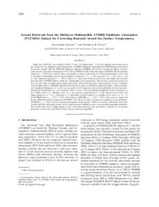
1.2 IPv6 header format The format of the IPv6 packet header is simplified from its counterpart in IPv4. The length of the IPv6 header increases to 40 bytes (from 20 bytes) and contains two 16-byte addresses (source and destination), preceded by 8 bytes of control information, as shown in Figure 1-1. 0
4 v e rs
12
16
tra ffic c la s s
24
31
flo w la b e l
p a ylo a d le n g th
nxt hdr
h o p lim it
s o u rc e a d d re s s
d e s tin a tio n a d d re s s
d a ta ....
Figure 1-1 IPv6 header format
Chapter 1. Internet Protocol version 6
3
The IPv4 header has two 4-byte addresses preceded by 12 bytes of control information and possibly followed by option data. The reduction of the control information and the elimination of options in the header for most IP packets optimizes the processing time per packet in a router. The infrequently used fields removed from the header are moved to optional extension headers when they are required. In Figure 1-1 on page 3: Vers
4-bit Internet Protocol version number: 6.
Traffic class
8-bit traffic class value. For more information, see 1.2.3, “Traffic class” on page 14.
Flow label
20-bit field. For more information, see 1.2.4, “Flow labels” on page 15.
Payload length
The length of the packet in bytes (excluding this header) encoded as a 16-bit unsigned integer. If length is greater than 64 KB, this field is 0 and an option header (Jumbo Payload) gives the true length.
Next header
Indicates the type of header immediately following the basic IP header. It can indicate an IP option header or an upper layer protocol. The protocol numbers used are the same as the ones used in IPv4. The next header field is also used to indicate the presence of extension headers, which provide the mechanism for appending optional information to the IPv6 packet. The following values appear in IPv6 packets, in addition to the values mentioned for IPv4: 41 Header 45
Interdomain Routing Protocol
46
Resource Reservation Protocol
58
IPv6 ICMP Packet
The following values are all extension headers: 0
Hop-by-Hop Options Header
43
IPv6 Routing Header
44
IPv6 Fragment Header
50
Encapsulating Security Payload
51
IPv6 Authentication Header
59
No Next Header
60
Destination Options Header
We describe different types of extension headers in 1.2.1, “Extension headers” on page 5. Hop limit
This field is similar to the IPv4 TTL field, but it is now measured in hops and not seconds. It was changed for two reasons: –
The IP protocol normally forwards datagrams faster than one hop per second and the TTL field is always decremented on each hop, so, in practice, it is measured in hops and not seconds.
–
Many IP implementations do not expire outstanding datagrams based on elapsed time.
The packet is discarded after the hop limit is decremented to zero.
4
IPv6 Introduction and Configuration
Source address
A 128-bit address. We describe IPv6 addresses in 1.2.2, “IPv6 addressing” on page 10.
Destination address A 128-bit address. We describe IPv6 addresses in 1.2.2, “IPv6 addressing” on page 10. A comparison of the IPv4 and IPv6 header formats shows that a number of IPv4 header fields have no direct equivalents in the IPv6 header: Type of service Type of service issues in IPv6 are handled by using the flow concept, described in 1.2.4, “Flow labels” on page 15. Identification, fragmentation flags, and fragment offset Fragmented packets have an extension header rather than fragmentation information in the IPv6 header. This configuration reduces the size of the basic IPv6 header, because higher-level protocols, particularly TCP, tend to avoid fragmentation of datagrams (this action reduces the IPv6 header processing costs for normal cases). IPv6 does not fragment packets en route to their destinations, only at the source. Header checksum Because transport protocols implement checksums, and because IPv6 includes an optional authentication header that can also be used to ensure integrity, IPv6 does not provide checksum monitoring of IP packets. Both TCP and UDP include a pseudo-IP header in the checksums they use, so in these cases, the IP header in IPv4 is being checked twice. TCP and UDP, and any other protocols using the same checksum mechanisms that run over IPv6, continue to use a pseudo-IP header, although the format of the pseudo-IPv6 header is different from the pseudo-IPv4 header. ICMP, IGMP, and any other protocols that do not use a pseudo-IP header over IPv4 use a pseudo-IPv6 header in their checksums. Options All optional values associated with IPv6 packets are contained in extension headers, ensuring that the basic IP header is always the same size.
1.2.1 Extension headers Every IPv6 packet starts with the basic header. In most cases, this header is the only header necessary to deliver the packet. Sometimes, however, it is necessary for additional information to be conveyed along with the packet to the destination or to intermediate systems on route (information that would previously been carried in the Options field in an IPv4 datagram). Extension headers are used for this purpose. Extension headers are placed immediately after the IPv6 basic packet header and are counted as part of the payload length. Each extension header (except for 59) has its own 8-bit Next Header field as the first byte of the header that identifies the type of the following header. This structure allows IPv6 to chain multiple extension headers together.
Chapter 1. Internet Protocol version 6
5
Figure 1-2 shows an example packet with multiple extension headers. 0
4 vers
12
16
traffic class
payload length
24
31
flow label nxt hdr: 0
hop limit
source address
destination address nxt hdr: 43
hdr length hop-by-hop options
nxt hdr: 44
hdr length routing information
nxt hdr: 51
reserved
fragment offset
M
fragment identification nxt hdr: 6
hdr length authentication data
TCP header and data
Figure 1-2 IPv6 packet that contains multiple extension headers
The length of each header varies, depending on type, but is always a multiple of 8 bytes. There are a limited number of IPv6 extension headers, any one of which can be present only once in the IPv6 packet (except for the Destination Options Header, 60, which can appear more than once). IPv6 nodes that originate packets are required to place extension headers in a specific order (numeric order, except for 60), although IPv6 nodes that receive packets are not required to verify that order. The order is important for efficient processing at intermediate routers. Routers are generally only interested in the hop-by-hop options and the routing header. After the router reads the options and header, it does not need to read further in the packet and can immediately forward the packet. When the Next Header field contains a value other than one for an extension header, this value indicates the end of the IPv6 headers and the start of the higher-level protocol data. IPv6 allows for the encapsulation of IPv6 within IPv6 (tunneling). This activity is done by using a Next Header value of 41 (IPv6). The encapsulated IPv6 packet can have its own extension headers. Because the size of a packet is calculated by the originating node to match the path MTU, IPv6 routers should not add extension headers to a packet. Instead, IPv6 routers should encapsulate the received packet within an IPv6 packet of their own making (which can be fragmented if necessary).
6
IPv6 Introduction and Configuration
Except for the hop-by-hop header (which must immediately follow the IP header if it is present), extension headers are not processed by any router on the packet's path except the final one.
Hop-by-hop header A hop-by-hop header contains options that must be examined by every node the packet traverses, as well as the destination node. It must immediately follow the IPv6 header (if present) and is identified by the special value 0 in the Next Header field of the IPv6 basic header. (This value is not actually a protocol number, but a special case to identify this unique type of extension header). Hop-by-hop headers contain variable length options of the format shown in Figure 1-3 (commonly known as the Type-Length-Value (TLV) format).
// type
length
value
// Figure 1-3 IPv6 Type-Length-Value (TLV) option format
Where: Type
The type of the option. The option types all have a common format (Figure 1-4).
t y p
0
1 x x
e
l e
2
n
g
3
t h
v a
4
5
6
l u
/
/
/
/
e
7
z z z z z
y
Figure 1-4 IPv6 Type-Length-Value (TLV) option type format
Where: xx
A 2-bit number, indicating how an IPv6 node that does not recognize the option should treat it: 0
Skip the option and continue.
1
Discard the packet quietly.
2
Discard the packet and inform the sender with an ICMP Unrecognized Type message.
3
Discard the packet and inform the sender with an ICMP Unrecognized Type message unless the destination address is a multicast address.
Chapter 1. Internet Protocol version 6
7
y
If set, this bit indicates that the value of the option might change en route. If this bit is set, the entire Option Data field is excluded from any integrity calculations performed on the packet.
zzzzz
The remaining bits define the option: 0
Pad1
1
PadN
194
Jumbo Payload Length
Length
The length of the option value field in bytes.
Value
The value of the option. This value depends on the type.
Hop-by-hop header option types Each extension header is an integer multiple of 8 bytes long. This arrangement allows 8-byte alignment for subsequent headers. This arrangement is used because processing is much more efficient if multibyte values are positioned on natural boundaries in memory (and today's processors have natural word sizes of 32 or 64 bits). In the same way, individual options are also aligned so that multibyte values are positioned on their natural boundaries. In many cases, this positioning results in the option headers being longer than otherwise necessary, but still allow nodes to process packets more quickly. To allow this alignment, two padding options are used in hop-by-hop headers: Pad1
An X'00' byte used for padding a single byte. For longer padding sequences, use the PadN option.
PadN
An option in the TLV format (see Figure 1-4 on page 7). The length byte gives the number of bytes of padding after the minimum two that are required.
The third option type in a hop-by-hop header is the Jumbo Payload Length. This option is used to indicate a packet with a payload size in excess of 65,535 bytes (which is the maximum size that can be specified by the 16-bit Payload Length field in the IPv6 basic header). When this option is used, the Payload Length in the basic header must be set to zero. This option carries the total packet size, less the 40-byte basic header. For details, see Figure 1-5. 0
8
16
24 type= C2
31 length=4
Jumbo Payload Length
Figure 1-5 Jumbo Payload Length option
Routing header The path that a packet takes through the network is normally determined by the network itself. Sometimes, however, the source wants more control over the route taken by the packet. It might want, for example, for certain data to take a slower but more secure route than would normally be taken.
8
IPv6 Introduction and Configuration
The routing header (see Figure 1-6) allows a path through the network to be predefined. The routing header is identified by the value 43 in the preceding Next Header field. It has its Next Header field as the first byte and a single-byte routing type as the second byte. The only type defined initially is type 0, strict/loose source routing, which operates in a similar way to source routing in IPv4. 0
8 next hdr
16 hdr length
24 type
31 addrs left
reserved
address[0]
address[1]
...
//
//
address[n-1]
Figure 1-6 IPv6 routing header
In Figure 1-6: Next hdr
The type of header after this one.
Hdr length
Length of this routing header, not including the first 8 bytes.
Type
Type of routing header. Currently, this field can have only the value 0, meaning strict/loose source routing.
Segments left
Number of route segments that remain, that is, number of explicitly listed intermediate nodes still to be visited before reaching the final destination.
Address 1..n
A series of 16-byte IPv6 addresses that make up the source route.
The first hop on the required path of the packet is indicated by the destination address in the basic header of the packet. When the packet arrives at this address, the router swaps the next address from the router extension header with the destination address in the basic header. The router also decrements the segments left field by one, and then forwards the packet.
Fragment header The source node determines the maximum transmission unit or MTU for a path before sending a packet. If the packet to be sent is larger than the MTU, the packet is divided into pieces, each of which is a multiple of 8 bytes and carries a fragment header. We provide details about the fragmentation header in “IPv6 packet fragmentation” on page 19.
Authentication header The authentication header is used to ensure that a received packet is not altered in transit and that it really came from the claimed sender. The authentication header is identified by the value 51 in the preceding Next Header field. For the format of the authentication header and further details about authentication, see 1.2.5, “IPv6 security” on page 15. Chapter 1. Internet Protocol version 6
9
Encapsulating Security Payload The Encapsulated Security Payload (ESP) is a special extension header, in that it can appear anywhere in a packet between the basic header and the upper layer protocol. All data that follows the ESP header is encrypted. For more details, see 1.2.5, “IPv6 security” on page 15.
Destination options header This header has the same format as the hop-by-hop header, but it is only examined by the destination node or nodes. Normally, the destination options are only intended for the final destination only and the destination options header is immediately before the upper-layer header. However, destination options can also be intended for intermediate nodes, in which case, they must precede a routing header. A single packet can, therefore, include two destination options headers. Currently, only the Pad1 and PadN types of options are specified for this header (see “Hop-by-hop header” on page 7). The value for the preceding Next Header field is 60.
1.2.2 IPv6 addressing The IPv6 address protocol is specified in RFC 4291 – IPv6 Address Architecture. IPv6 uses a 128-bit address instead of the 32-bit address of IPv4. That theoretically allows for as many as 340,282,366,920,938,463,463,374,607,431,768,211,456 addresses. Even when used with the same efficiency as today's IPv4 address space, that still allows for 50,000 addresses per square meter of land on Earth. The IPv6 address protocol provides flexibility and scalability: It allows multilevel subnetting and allocation from a global backbone to an individual subnet within an organization. It improves multicast scalability and efficiency through scope constraints. It adds an address for server node clusters, where one server can respond to a request to a group of nodes. The large IPv6 address space is organized into a hierarchical structure to reduce the size of backbone routing tables. IPv6 addresses are represented in the form of eight hexadecimal numbers divided by colons, for example: FE80:0000:0000:0000:0001:0800:23E:F5DB To shorten the notation of addresses, leading zeros in any of the groups can be omitted, for example: FE80:0:0:0:1:800:23E7:F5DB Finally, a group of all zeros, or consecutive groups of all zeros, can be substituted by a double colon, for example: FE80::1:800:23E7:F5DB Double colons: The double colon shortcut can be used only once in the notation of an IPv6 address. If there are more groups of all zeros that are not consecutive, only one can be substituted by the double colon; the others must be noted as 0. The IPv6 address space is organized by using format prefixes, similar to telephone country and area codes, that logically divide it in the form of a tree so that a route from one network to another can easily be found.
10
IPv6 Introduction and Configuration
Table 1-1shows the prefixes that are assigned so far. Table 1-1 IPv6 - format prefix allocation Allocation
Prefix (bin)
Start of address range (hex)
Mask length (bits)
Fraction of address space
Reserved
0000 0000
0:: /8
8
1/256
Reserved for NSAP
0000 001
200:: /7
7
1/128
Reserved for IPX
0000 010
400:: /7
7
1/128
Aggregatable global unicast addresses
001
2000:: /3
3
1/8
Link-local unicast
1111 1110 10
FE80:: /10
10
1/1024
Site-local unicast
1111 1110 11
FEC0:: /10
10
1/1024
Multicast
1111 1111
FF00:: /8
8
1/256
Total allocation
15%
In the following sections, we describe the types of addresses that IPv6 defines.
Unicast address A unicast address is an identifier assigned to a single interface. Packets sent to that address are delivered only to that interface. Special purpose unicast addresses are defined as follows: Loopback address (::1): This address is assigned to a virtual interface over which a host can send packets only to itself. It is equivalent to the IPv4 loopback address 127.0.0.1. Unspecified address (::):This address is used as a source address by hosts while performing auto-configuration. It is equivalent to the IPv4 unspecified address 0.0.0.0. IPv4-compatible address (::): Addresses of this kind are used when IPv6 traffic needs to be tunneled across existing IPv4 networks. The endpoint of such tunnels can be either hosts (automatic tunneling) or routers (configured tunneling). IPv4-compatible addresses are formed by placing 96 bits of zero in front of a valid 32-bit IPv4 address. For example, the address 1.2.3.4 (hex 01.02.03.04) becomes ::0102:0304. IPv4-mapped address (::FFFF:): Addresses of this kind are used when an IPv6 host needs to communicate with an IPv4 host. This address requires a dual stack host or router for header translations. For example, if an IPv6 node wants to send data to host with an IPv4 address of 1.2.3.4, it uses a destination address of ::FFFF:0102:0304. Link-local address: Addresses of this kind can be used only on the physical network to which a host's interface is attached. Site-local address: Addresses of this kind cannot be routed into the Internet. They are the equivalent of IPv4 networks for private use (10.0.0.0, 176.16.0.0-176.31.0.0, and 192.168.0.0-192.168.255.0).
Chapter 1. Internet Protocol version 6
11
Global unicast address format IPv6 unicast addresses are aggregatable with prefixes of arbitrary bit-length, similar to IPv4 addresses under Classless Inter-Domain Routing. The latest global unicast address format, as specified in RFC 4291 – IPv6 Address Architecture and RFC 3587 – IPv6 Global Unicast Address Format, is expected to become the predominant format used for IPv6 nodes connected to the Internet. Unicast format: This note is intended for readers who worked on the previous unicast format. For new readers, you can skip this special note. The historical IPv6 unicast address used a two-level allocation scheme that has been replaced by a coordinated allocation policy defined by the Regional Internet Registries (RIRs). There are two reasons for this major change: Part of the motivation for obsoleting the old TLA/NLA structure is technical; for example, there is concern that TLA/NLA is not the technically best approach at this stage of the deployment of IPv6. Another part of the reason for new allocation of IPv6 addresses is related to policy and to the stewardship of the IP address space and routing table size, which the RIRs manage for IPv4. The Subnet Local Aggregator (SLA) field in the original Unicast Address Structure remains in function, but with a different name called “subnet ID”. Figure 1-7 shows the general format for IPv6 global unicast addresses.
Interface ID
Figure 1-7 Global unicast address format
Where: Global Routing Prefix
A value assigned to a site for a cluster of subnets/links. The global routing prefix is structured hierarchically by the RIRs and ISPs.
Subnet ID
An identifier of a subnet within the site. The subnet field is structured hierarchically by site administrators.
Interface ID
Interface identifiers in IPv6 unicast addresses are used to identify interfaces on a link. They are required to be unique within a subnet prefix. Do not assign the same interface identifier to different nodes on a link. They can also be unique over a broader scope. In some cases, an interface's identifier is derived directly from that interface's link layer address. The same interface identifier can be used on multiple interfaces on a single node if they are attached to different subnets.
All unicast addresses, except the addresses that start with binary value 000, have interface IDs that are 64 bits long and constructed in Modified EUI-64 format.
12
IPv6 Introduction and Configuration
Multicast address A multicast address is an identifier assigned to a set of interfaces on multiple hosts. Packets sent to that address are delivered to all interfaces corresponding to that address. There are no broadcast addresses in IPv6, their function being superseded by multicast addresses. Figure 1-8 shows the format of an IPv6 multicast address.
0
8 FP
12
16
127 Group ID
Flags Scope
Figure 1-8 IPv6 multicast address format
Where: FP
Format Prefix: 1111 1111.
Flags
Set of four flag bits. Only the low-order bit currently has any meaning, as follows:
Scope
Group ID
0000
Permanent address assigned by a numbering authority.
0001
Transient address. Addresses of this kind can be established by applications as required. When the application ends, the address is released by the application and can be reused.
4-bit value that indicates the scope of the multicast. Possible values are: 0
Reserved.
1
Confined to interfaces on the local node (node-local).
2
Confined to nodes on the local link (link-local).
5
Confined to the local site.
8
Confined to the organization.
E
Global scope.
F
Reserved.
Identifies the multicast group.
For example, if the NTP servers group is assigned a permanent multicast address, with a group ID of &hex.101, then: FF02::101 means that all NTP servers are on the same link as the sender. FF05::101 means that all NTP servers are on the same site as the sender. Certain special purpose multicast addresses are predefined as follows: FF01::1
All interfaces are node-local. Defines all interfaces on the host itself.
FF02::1
All nodes are link-local. Defines all systems on the local network.
FF01::2
All routers are node-local. Defines all routers local to the host itself.
FF02::2
All routers are link-local. Defines all routers on the same link as the host.
FF05::2
All routers are site-local. Defines all routers on the same site as the host. Chapter 1. Internet Protocol version 6
13
FF02::B
Mobile agents are link-local.
FF02::1:2
All DHCP agents are link-local.
FF05::1:3
All DHCP servers are site-local.
For a complete listing of reserved multicast addresses, see the IANA documentation– IPv6 Multicast Addresses (Assignments). That document also defines a special multicast address known as the solicited node address, which has the format FF02::1:FFxx:xxxx, where xx xxxx is taken from the last 24 bits of a node’s unicast address. For example, the node with an IPv6 address of 4025::01:800:100F:7B5B belongs to the multicast group FF02::1:FF 0F:7B5B. The solicited node address is used by ICMP for neighbor discovery and to detect duplicate addresses.
Anycast address An anycast address is a special type of unicast address that is assigned to interfaces on multiple hosts. Packets sent to such an address are delivered to the nearest interface with that address. Routers determine the nearest interface based upon their definition of distance, for example, hops in case of RIP or link state in case of OSPF. Anycast addresses use the same format as unicast addresses and are indistinguishable from them. However, a node that is assigned an anycast address must be configured to be aware of this fact. RFC 4291 – IPv6 Address Architecture currently specifies the following restrictions on anycast addresses: An anycast address must not be used as the source address of a packet. Any anycast address can be assigned only to a router. A special anycast address, the subnet-router address, is predefined. This address consists of the subnet prefix for a particular subnet followed by trailing zeros. This address can be used when a node needs to contact a router on a particular subnet and it does not matter which router is reached (for example, when a mobile node needs to communicate with one of the mobile agents on its “home” subnet).
1.2.3 Traffic class The 8-bit traffic class field allows applications to specify a certain priority for the traffic they generate, thus introducing the concept of class of service. This concept enables the prioritization of packets, as in Differentiated Services. The structure of the traffic class field is illustrated in Figure 1-9
0
5 6 DSCP
Figure 1-9 Traffic class field
14
IPv6 Introduction and Configuration
7 ECN
Where: DSCP
Differentiated Services Code Point (6 bits) It provides various code sets to mark the per-hop behavior for a packet that belongs to a service class.
ECN
Explicit Congestion Notification (2 bits) It allows routers to set congestion indications instead of dropping the packets. This configuration avoids delays in retransmissions, while allowing active queuing management.
1.2.4 Flow labels IPv6 introduces the concept of a flow, which is a series of related packets from a source to a destination that requires a particular type of handling by the intervening routers, for example, real-time service. The nature of that handling can either be conveyed by options attached to the datagrams (that is, by using the IPv6 hop-by-hop options header) or by a separate protocol (such as Resource Reservation Protocol (RSVP)). All packets that belong to the same flow must be sent with the same source address, destination address, and flow label. The handling requirement for a particular flow label is known as the state information, which is cached at the router. When packets with a known flow label arrive at the router, the router can efficiently decide how to route and forward the packets without needing to examine the rest of the header for each packet. The maximum lifetime of any flow-handling state established along a flow's path must be specified as part of the description of the state-establishment mechanism, for example, the resource reservation protocol or the flow-setup hop-by-hop option. A source must not reuse a flow label for a new flow within the maximum lifetime of any flow-handling state that might be established for the prior use of that flow label. There can be multiple active flows between a source and a destination, as well as traffic that is not associated with any flow. Each flow is distinctly labeled by the 24-bit flow label field in the IPv6 packet. A flow is uniquely identified by the combination of a source address and a non-zero flow label. Packets that do not belong to a flow carry a flow label of zero. A flow label is assigned to a flow by the flow's source node. New flow labels must be chosen (pseudo-)randomly and uniformly from the range 1 to FFFFF hex. The purpose of the random allocation is to make any set of bits within the Flow Label field suitable for use as a hash key by routers for looking up the state associated with the flow. See RFC 3697 - IPv6 Flow Label Specification for further details about the use of the flow label.
1.2.5 IPv6 security There are two optional headers defined for security purposes: Authentication Header (AH) Encapsulated Security Payload (ESP) AH and ESP in IPv6 support authentication, data integrity, and (optionally) confidentiality. AH conveys the authentication information in an IP package, while ESP carries the encrypted data of the IP package.
Chapter 1. Internet Protocol version 6
15
Either or both headers can be implemented alone or combined to achieve different levels of user security requirements. They can also be combined with other optional headers to provision security features. For example, a routing header can be used to list the intermediate secure nodes for a packet to visit on the way, thus allowing the packet to travel only through secure routers. IPv6 requires support for IPSec as a mandatory standard. This mandate provides a standards-based solution for network security needs and promotes interoperability.
Authentication header The authentication header is used to ensure that a received packet has not been altered in transit and that it really came from the claimed sender (Figure 1-10). The authentication header is identified by the value 51 in the preceding Next Header field. The format of the authentication header and further details are specified in RFC 4302 - IP Authentication Header.
Security Parameters Index (SPI) Sequence Number (SN) Field Integrity Check Value-ICV
Figure 1-10 IPV6 security authentication header
Where: Security Parameters Index (SPI)
The SPI is an arbitrary 32-bit value that is used by a receiver to identify the Security Association (SA) to which an incoming packet is bound. For a unicast SA, the SPI can be used by itself to specify an SA, or it can be used in conjunction with the IPSec protocol type (in this case, AH).The SPI field is mandatory. Traffic to unicast SAs described earlier must be supported by all AH implementations. If an IPSec implementation supports multicast, it must support multicast SAs by using a special de-multiplexing algorithm.
Sequence Number
16
IPv6 Introduction and Configuration
This unsigned 32-bit field contains a counter value that increases by one for each packet sent, that is, a per-SA packet sequence number.
For a unicast SA or a single-sender multicast SA, the sender must increment this field for every transmitted packet. Sharing an SA among multiple senders is permitted, though generally not recommended. The field is mandatory and must always be present even if the receiver does not elect to enable the anti-replay service for a specific SA. Processing of the Sequence Number field is at the discretion of the receiver, but all AH implementations must be capable of performing the processing, Thus, the sender must always transmit this field, but the receiver does not need to act upon it. The sender's counter and the receiver's counter are initialized to 0 when an SA is established. The first packet sent by using an SA has a sequence number of 1; if anti-replay is enabled (the default), the transmitted sequence number must never be allowed to cycle. Therefore, the sender's counter and the receiver's counter must be reset (by establishing a new SA and thus a new key) before the transmission of the 232 packet on an SA. Extended (64-bit) Sequence Number (ESN)
To support high-speed IPSec implementations, a new option for sequence numbers should be offered, as an extension to the current, 32-bit sequence number field. Use of an Extended Sequence Number (ESN) must be negotiated by an SA management protocol. The ESN feature is applicable to multicast as well as unicast SAs.
Integrity Check Value (ICV)
This field is a variable-length field that contains the Integrity Check Value (ICV) for this packet. The field must be an integral multiple of 32 bits (IPv4 or IPv6) in length. All implementations must support such padding and must insert only enough padding to satisfy the IPv4/IPv6 alignment requirements.
Chapter 1. Internet Protocol version 6
17
Encapsulating Security Payload The Encapsulated Security Payload (ESP) is defined in RFC 4303 - IP Encapsulating Security Payload (ESP). All data that follows the ESP header is encrypted. Figure 1-11 illustrates the ESP structure with the additional field explained after the figure.
Security Parameters Index (SPI) Sequence Number Field
Payload Padding Next Header
Length
Integrity Check Value-ICV
Figure 1-11 IPv6 ESP
The packet begins with the Security Parameters Index (SPI) and Sequence Number (SN). Following these fields is the Payload Data, which has a substructure that depends on the choice of encryption algorithm and mode and on the usage of TFC padding. Payload Data is a variable-length field that contain data (from the original IP packet). It is a mandatory field and is an integral number of bytes in length. Following the Payload Data are Padding and Pad Length fields and the Next Header field. The optional Integrity Check Value (ICV) field completes the packet. If the algorithm used to encrypt the payload requires cryptographic synchronization data, for example, an Initialization Vector (IV), this data is carried in the Payload field. Any encryption algorithm that requires an explicit, per-packet synchronization data must indicate the length, any structure for such data, and the location of this data. If such synchronization data is implicit, the algorithm for deriving the data must be part of the algorithm definition. The beginning of the next layer protocol header must be aligned relative to the beginning of the ESP header. For IPv6, the alignment is a multiple of 8 bytes.
1.2.6 Packet sizes All IPv6 nodes are expected to dynamically determine the maximum transmission unit (MTU) supported by all links along a path (as described in RFC 1191 – Path MTU Discovery) and source nodes send only packets that do not exceed the path MTU. IPv6 routers, therefore, do not have to fragment packets in the middle of multihop routes, which allows for much more efficient use of paths that traverse diverse physical transmission media. IPv6 requires that every link supports an MTU of 1280 bytes or greater.
18
IPv6 Introduction and Configuration
IPv6 packet fragmentation The source node determines the MTU for a path before sending a packet. If the packet sent is larger than the MTU, the packet is divided into pieces, each of which is a multiple of 8 bytes and carries a fragment header. The fragment header is identified by the value 44 in the preceding Next Header field and has the following format (Figure 1-12). 0
8 next hdr
16 hdr length
24 type
31 segments left
reserved
address[0]
address[1]
...
//
//
address[n-1]
Figure 1-12 IPv6 fragment header
Where: Nxt hdr
The type of next header after this one.
Reserved
8-bit reserved field; initialized to zero for transmission and ignored on reception.
Fragment offset
A 13-bit unsigned integer that gives the offset, in 8-byte units, of the following data relative to the start of the original data before it was fragmented.
Res
2-bit reserved field; initialized to zero for transmission and ignored on reception.
M
More flag. If set, it indicates that this fragment is not the last one.
Fragment identification
This identifier is an unambiguous identifier used to identify fragments of the same datagram. It is similar to the IPv4 Identifier field, but it is twice as wide.
1.3 DNS in IPv6 With the introduction of 128-bit addresses, IPv6 makes it even more difficult for the network user to be able to identify another network user with the IP address of the user’s network device. The use of the Domain Name System (DNS) therefore becomes even more of a necessity.
Chapter 1. Internet Protocol version 6
19
A number of extensions to DNS are specified to support the storage and retrieval of IPv6 addresses. These extensions are defined in RFC 3596 – DNS Extensions to Support IP Version 6, which is a proposed standard with elective status. However, there is also work in progress on usability enhancements to this RFC, described in an Internet draft of the same name. The following extensions are specified: A new resource record type, AAAA, which maps the domain name to the IPv6 address A new domain, which is used to support address-to-domain name lookups A change to the definition of existing queries so that they perform correct processing on both A and AAAA record types
1.3.1 Format of IPv6 resource records RFC 3596 – DNS Extensions to Support IP Version 6 defines the format of the AAAA record as similar to an A resource record, but with the 128-bit IPv6 address encoded in the data section and a Type value of 28 (decimal). A special domain, IP6.INT, is defined for inverse (address-to-host name) lookups (similar to the in-addr.arpa domain used in IPv4). As in IPv4, the address must be entered in reverse order, but hexadecimal digits are used rather than decimal notation. For example, for the IPv6 address 2222:0:1:2:3:4:5678:9ABC, the inverse domain name entry is: c.b.a.9.8.7.6.5.4.0.0.0.3.0.0.0.2.0.0.0.1.0.0.0.0.0.0.0.2.2.2.2.IP6.INT. So, if the previous address relates to the node ND1.test.com, we might expect to see the following entries in the name server zone data: $origin test.com. ND1
99999 IN AAAA 2222:0:1:2:3:4:5678:9ABC
cba98765400030002000100000002222.IP6.INT. IN
PTR ND1 1
Proposed changes to resource records The IPv6 addressing system is designed to allow for multiple addresses on a single interface and to facilitate address renumbering (for example, when a company changes one of its service providers). RFC 3596 – DNS Extensions to Support IP Version 6 proposes changes to the format of the AAAA resource record to simplify network renumbering. The proposed format of the data section of the AAAA record is shown in Figure 1-13.
IPv6 address
P
domain name
Figure 1-13 AAAA resource record - proposed data format
1
20
All characters making up the reversed IPv6 address in this PTR entry should be separated by a period(.). These periods are omitted in this example for clarity.
IPv6 Introduction and Configuration
Where: IPv6 address
128-bit address (contains only the lower bits of the address)
P
Prefix length (0 - 128)
Domain name
The domain name of the prefix
To see how this format works, consider the example shown in Figure 1-14.
2111
2122
TOP1
TOP2 OOCD
PROV1
ction new conne
OOAB
OOBC
OOA1
PROV2
OOB1 X
TEST.COM
ND1 10005A123456
Figure 1-14 Prefix numbering example
Site X is multihomed to two providers, PROV1 and PROV2. PROV1 gets its transit services from top-level provider TOP1. PROV2 gets its service from TOP2. TOP1 has the top-level aggregate (TLA ID + format prefix) of 2111. TOP2 has the TLA of 2222. TOP1 is assigned the next-level aggregate (NLA) of 00AB to PROV1. PROV2 is assigned the NLA of 00BC by TOP2. PROV1 is assigned the subscriber identifier 00A1 to site X. PROV2 is assigned the subscriber identifier 00B1 to site X. Node ND1, at site X, which has the interface token of 10005A123456, is therefore configured with the following two IP addresses: 2111:00AB:00A1::1000:5A12:3456 2222:00BC:00B1::1000:5A12:3456 Site X is represented by the domain name test.com. Each provider has their own domain, top1.com, top2.com, prov1.com, and prov2.com. In each of these domains, an IP6 subdomain is created that is used to hold prefixes. The node ND1 can now be represented by the following entries in the DNS: ND1.TEST.COM AAAA ::1000:5A12:3456 80 IP6.TEST.COM
Chapter 1. Internet Protocol version 6
21
IP6.TEST.COM AAAA 0:0:00A1:: 32 IP6.PROV1.COM IP6.TEST.COM AAAA 0:0:00B1:: 32 IP6.PROV2.COM IP6.PROV1.COM AAAA 0:00AB:: 16 IP6.TOP1.COM IP6.PROV2.COM AAAA 0:00BC:: 16 IP6.TOP2.COM IP6.TOP1.COM AAAA 2111:: IP6.TOP2.COM AAAA 2222:: This format simplifies the job of the DNS administrator considerably and makes renumbering changes much easier to implement. Say, for example, site X decides to stop using links from providers PROV1 and PROV2 and invests in a connection direct from the top-level service provider TOP1 (who allocates the next-level aggregate 00CD to site X). The only change necessary in the DNS is for the two IP6.TEST.COM entries to be replaced with a single entry, as follows: IP6.TEST.COM AAAA 0:00CD:: 16 IP6.TOP1.COM
1.4 DHCP in IPv6 Although IPv6 introduces stateless address auto-configuration, DHCP retains its importance as the stateful alternative for those sites that want to have more control over their addressing scheme. Used together with stateless auto-configuration, DHCP provides a means of passing additional configuration options to nodes after they obtain their addresses. RFC 3315 - Dynamic Host Configuration Protocol for IPv6 (DHCPv6) defines DHCP in IPv6, and RFC 3736 - Stateless Dynamic Host Configuration Protocol (DHCP) Service for IPv6 defines stateless DHCP for IPv6. DHCPv6 has some significant differences from DHCPv4, because it takes advantage of some of the inherent enhancements of the IPv6 protocol. Some of the principal differences include: As soon as a client boots, it already has a link-local IP address, which it can use to communicate with a DHCP server or a relay agent. The client uses multicast addresses to contact the server, rather than broadcasts. IPv6 allows the use of multiple IP addresses per interface and DHCPv6 can provide more than one address when requested. Some DHCP options are now unnecessary. Default routers, for example, are now obtained by a client using IPv6 neighbor discovery. DHCP messages (including address allocations) appear in IPv6 message extensions, rather than in the IP header as in IPv4. There is no requirement for BOOTP compatibility. There is a new reconfigure message, which is used by the server to send configuration changes to clients (for example, the reduction in an address lifetime). Clients must continue to listen for reconfigure messages after they receive their initial configuration.
22
IPv6 Introduction and Configuration
1.4.1 DHCPv6 messages The following DHCPv6 messages are currently defined: DHCP Solicit
This message is an IP multicast message. The DHCP client forwards the message to FF02::1:2, the well-known multicast address for all DHCP agents (relays and servers). If received by a relay, the relay forwards the message to FF05::1:3, the well-known multicast address for all DHCP servers.
DHCP Advertise
This message is a unicast message sent in response to a DHCP Solicit. A DHCP server responds directly to the soliciting client if on the same link, or through the relay agent if the DHCP Solicit is forwarded by a relay. The advertise message can contain one or more extensions (DHCP options).
DHCP Request
After the client locates the DHCP server, the DHCP request (unicast message) is sent to request an address, configuration parameters, or both. The request must be forwarded by a relay if the server is not on the same link as the client. The request can contain extensions (options specified by the client) that can be a subset of all the options available on the server.
DHCP Reply
An IP unicast message sent in response to a DHCP request (can be sent directly to the client or through a relay). Extensions contain the address, parameters, or both committed to the client.
DHCP Release
An IP unicast sent by the client to the server, informing the server of resources that are being released.
DHCP Reconfigure
An IP unicast or multicast message, sent by the server to one or more clients, to inform them that there is new configuration information available. The client must respond to this message with a DHCP request to request these new changes from the server.
For further details about DHCPv6, see RFC 3315 - Dynamic Host Configuration Protocol for IPv6 (DHCPv6) and RFC 3736 - Stateless Dynamic Host Configuration Protocol (DHCP) Service for IPv6.
1.5 IPv6 mobility support There are some unique requirements in mobile network applications. For example, while a mobile station or mobile node is always logically identified by its home address, it can physically move around in the IPv6 Internet. For a mobile node to remain reachable while moving, each mobile node must have a temporary address when it is newly attached to a visiting location network. While situated away from its home, a mobile node is associated with a care-of address, which provides information about the mobile node's current location. IPv6 packets addressed to a mobile node's home address are transparently routed to its care-of address. IPv6 mobile network cache the binding of a mobile node's home address with its care-of address, and then send any packets destined for the mobile node directly to it at this care-of address.
Chapter 1. Internet Protocol version 6
23
At any traveling location, there are always multiple service providers for competition in the wireless market, and multiple network prefixes are available. Mobile IPv6 provides binding support for the address to an attached visiting network. The native IPv6 routing header also supports route selection for a packet to go through the wanted networks. The capability allows network service provider selection. And as a result, it enforces a security and service policy by going through only authorized gateway service nodes. There are certain enhancements in IPv6 that are suited to the mobile environment, including: A mobile node uses a temporary address while away from its home location. It can use the IPv6 Destination Optional header to store its home address. An intended destination can access the field to get the mobile node’s home address for substitution when processing the packet. A mobile station can list the all routing header for the packets to follow particular paths to connect to a selective service provider network. Also, most packets sent to a mobile node while it is away from its home location can be tunneled by using IPv6 routing (extension) headers, rather than a complete encapsulation, as used in Mobile IPv4, which reduces the processing cost of delivering packets to mobile nodes. Unlike Mobile IPv4, there is no requirement for routers to act as “foreign agents” on behalf of the mobile node, because neighbor discovery and address auto-configuration allow the node to operate away from home without any special support from a local router. The dynamic home agent address discovery mechanism in Mobile IPv6 returns a single reply to the mobile node. The directed broadcast approach used in IPv4 returns separate replies from each home agent. To better use the native IPv6 capabilities in next generation (3G) wireless network and service, the IPv6 working group, and 3rd Generation Partnership Project (or 3GPP) working group, has conducted joint discussions. As a result of adopting native IPv6 features (for example, IPv6 address prefix allocation), they ensure that handsets are compatible with mobile computers in sharing drivers and related software. On top of the native IPv6 support to mobility, standard extensions are added to ensure that any nodes, whether mobile or stationary, can communicate efficiently with a mobile node. Additional Mobile IPv6 features include: Mobile IPv6 allows a mobile node to move from one link to another without changing the mobile node's “home address.” Packets can be routed to the mobile node by using this address regardless of the mobile node's current point of attachment to the Internet. The mobile node can also continue to communicate with other nodes (stationary or mobile) after moving to a new link. The movement of a mobile node away from its home link is thus transparent to transport and higher-layer protocols and applications. The Mobile IPv6 protocol is as suitable for mobility across homogeneous media as for mobility across heterogeneous media. For example, Mobile IPv6 facilitates node movement from one Ethernet segment to another as well as node movement from an Ethernet segment to a wireless LAN cell, with the mobile node's IP address remaining unchanged despite such movement. You can think of the Mobile IPv6 protocol as solving the network layer mobility management problem. Some mobility management applications, for example, handover among wireless transceivers, each of which covers only a small geographic area, are solved by using link layer techniques. As another example, in many current wireless LAN products, link layer mobility mechanisms allow a “handover” of a mobile node from one cell to another, re-establishing link layer connectivity to the node in each new location.
24
IPv6 Introduction and Configuration
Handovers: In mobility terminology, a handover deals with moving from a cell to another cell. But the concept can be generalized into a wireless-wireline integration environment. For example: Layer-2 handover provides a process by which the mobile node changes from one link layer connection to another in a change of a wireless or wireline access point. Subsequent to an L2 handover, a mobile node detects a change in an on-link subnet prefix that requires a change in the primary care-of address. Mobile IPv6 route optimization avoids congestion of the home network by getting a mobile node and a corresponding node to communicate directly. Route optimization can operate securely even without prearranged Security Associations. Support for route optimization is a fundamental part of the protocol, rather than as a nonstandard set of extensions. It is expected that route optimization can be deployed on a global scale between all mobile nodes and correspondent nodes. The IPv6 Neighbor Unreachability Detection ensures symmetric reachability between the mobile node and its default router in the current location. Most packets sent to a mobile node while away from home in Mobile IPv6 are sent by using an IPv6 routing header rather than IP encapsulation, increasing efficiencies when compared to Mobile IPv4. Mobile IPv6 is decoupled from any particular link layer, because it uses IPv6 Neighbor Discovery instead of Address Resolution Protocol (ARP). This configuration also improves the robustness of the protocol. Mobile IPv6 defines a new IPv6 protocol by using the Mobility header to carry the following messages: – Home Test Init, Home Test, Care-of Test Init, and Care-of Test These four messages perform the return routability procedure from the mobile node to a correspondent node. – Binding Update and Acknowledgement A Binding Update is used by a mobile node to notify a node or the mobile node's home agent of its current binding. The Binding Update sent to the mobile node's home agent to register its primary care-of address is marked as a “home registration.” – Binding Refresh Request A Binding Refresh Request is used by a correspondent node to request that a mobile node re-establish its binding with the correspondent node. The association of the home address of a mobile node with a care-of address for that mobile node remains for the life of that association. Mobile IPv6 also introduces four new ICMP message types, two for use in the dynamic home agent address discovery mechanism, and two for renumbering and mobile configuration mechanisms: – The following two new ICMP message types are used for home agent address discovery: Home Agent Address Discovery Request and Home Agent Address Discovery Reply. – The next two message types are used for network renumbering and address configuration on the mobile node: Mobile Prefix Solicitation and Mobile Prefix Advertisement.
Chapter 1. Internet Protocol version 6
25
In summary, IPv6 provides native support for mobile applications. Additional extensions have also been added to Mobile IPv6 protocols. IETF is cooperating with other standard organizations, such as 3GPP in Mobile IPv6. For more details, see RFC 3775 - Mobility Support in IPv6.
26
IPv6 Introduction and Configuration
2
Chapter 2.
Internet Control Message Protocol version 6 The IP protocol concerns itself with moving data from one node to another. However, in order for the IP protocol to perform this task successfully, there are many other functions that need to be carried out: error reporting, route discovery, and diagnostic tests, to name a few. All these tasks are carried out by the Internet Control Message Protocol. In addition, Internet Control Message Protocol Version 6 (ICMPv6) carries out the tasks of conveying multicast group membership information, a function that was previously performed by the Internet Group Management Protocol (IGMP) in IPv4 and address resolution, previously performed by ARP. This chapter describes the functions of ICMP in an IPv6 network.
© Copyright IBM Corp. 2012. All rights reserved.
27
2.1 ICMPv6 messages ICMPv6 messages and their usage are specified in RFC 4443 – Internet Control Message Protocol (ICMPv6) for the Internet Protocol Version 6 (IPv6) Specification and RFC 4861 – Neighbor Discovery for IP Version 6 (IPv6). Both RFCs are draft standards with a status of elective. Every ICMPv6 message is preceded by an IPv6 header (and possibly some IP extension headers). The ICMPv6 header is identified by a Next Header value of 58 in the immediately preceding header. ICMPv6 messages all have a similar format, as shown in Figure 2-1.
0
8
Type
16 Code
31
C hecksum
B o d y o f IC M P M e s s a g e
Figure 2-1 ICMPv6 general message format
Where: Type
There are two classes of ICMPv6 messages. Error messages have a Type 0 - 127. Informational messages have a Type 128 - 255. 1 2 3 4 128 129 130 131 132 133 134 135 136 137
Destination Unreachable Packet Too Big Time (Hop Count) Exceeded Parameter Problem Echo Request Echo Reply Group Membership Query Group Membership Report Group Membership Reduction Router Solicitation Router Advertisement Neighbor Solicitation Neighbor Advertisement Redirect Message
Code
Varies according to message type.
Checksum
Used to detect data corruption in the ICMPv6 message and parts of the IPv6 header.
Body of message
Varies according to message type.
For full details of ICMPv6 messages for all types, see RFC 4443 – Internet Control Message Protocol (ICMPv6) for the Internet Protocol Version 6 (IPv6) Specification.
28
IPv6 Introduction and Configuration
2.1.1 Neighbor discovery Neighbor discovery is an ICMPv6 function that enables a node to identify other hosts and routers on its links. The node needs to know of at least one router so that it knows where to forward packets if a target node is not on its local link. Neighbor discovery also allows a router to redirect a node to use a more appropriate router if the node initially made an incorrect choice.
Address resolution Figure 2-2 shows a simple Ethernet LAN segment with four IPv6 workstations. IP MAC
FE80::0800:5A12:3456 08005A123456
IP MAC
A
FE80::0800:5A12:3458 08005A123458 C
B
D
IP MAC
FE80::0800:5A12:3457 08005A123457
IP MAC
FE80::0800:5A12:3459 08005A123459
Figure 2-2 IPv6 address resolution example
Workstation A needs to send data to workstation B. It knows the IPv6 address of workstation B, but it does not know how to send a packet, because it does not know its MAC address. To discover this information, it sends a neighbor solicitation message, using the format shown in Figure 2-3.
6
Traffic Class Payload = 32
Flow Label Next = 58
Hops = 255
Source Address - FE80::0800:5A12:3456
IP Header
Destination Address - FF02::1:5A12:3458 Type = 135
Code = 0
Checksum
Reserved = 0
ICMP Message
Target Address - FE80::0800:5A12:3458 Opt Code=1 Opt Len=1 Source Link Layer Address = 08005A123456
Figure 2-3 Neighbor solicitation message format
Chapter 2. Internet Control Message Protocol version 6
29
Where: Next
58 (for the following ICMP message header).
Hops
Any solicitation packet that does not have hops set to 255 is discarded. This setting ensures that the solicitation does not cross a router.
Destination address This address is the solicited node address for the target workstation (a special type of multicast). Every workstation must respond to its own solicited node address but other workstations ignore it. This setting is an improvement over ARP in IPv4, which uses broadcast frames that must be processed by every node on the link. In the ICMP message itself: Type
135 (Neighbor Solicitation).
Target address
This address is the known IP address of the target workstation.
Source link layer address
This address is useful to the target workstation and saves it from having to initiate a neighbor discovery process of its own when it sends a packet back to the source workstation.
The response to the neighbor solicitation message is a neighbor advertisement, which has the format shown in Figure 2-4. 6
Traffic Class Payload = 32
Flow Label Next = 58
Hops = 255
Source Address - FE80::0800:5A12:3458 FE80::0800:5A12:3456
IP Header
Destination Address - FE80::0800:5A12:3456 Type = 136
Code = 0
R S O
ICMP Message
Checksum
Reserved = 0
Target Address - FE80::0800:5A12:3458 Opt Code=2 Opt Len=1 Target Link Layer Address = 08005A123458
Figure 2-4 Neighbor advertisement message
The neighbor advertisement is addressed directly back to workstation A. The ICMP message option contains the target IP address together with the target's link layer (MAC) address. Consider the following flags in the advertisement message: R
Router flag. This bit is set on if the sender of the advertisement is a router.
S
Solicited flag. This bit is set on if the advertisement is in response to a solicitation.
O
Override flag. When this bit is set on, the receiving node must update an existing cached link layer entry in its neighbor cache.
After workstation A receives this packet, it commits the information to memory in its neighbor cache, and then forwards the data packet that it originally wanted to send to workstation C.
30
IPv6 Introduction and Configuration
Neighbor advertisement messages can also be sent by a node to force updates to neighbor caches if it becomes aware that its link layer address has changed.
Router and prefix discovery Figure 2-2 on page 29 shows a simple network example. In a larger network, particularly one connected to the Internet, the neighbor discovery process is used to find nodes on the same link in the same way. However, it is more than likely that a node needs to communicate not just with other nodes on the same link, but with nodes on other network segments that might be anywhere in the world. In this case, there are two important pieces of information that a node needs to have: The address of a router that the node can use to reach the rest of the world The prefix (or prefixes) that define the range of IP addresses on the same link as the node that can be reached without going through a router Routers use ICMP to convey this information to hosts with router advertisements. The format of the router advertisement message is shown in Figure 2-5. The message generally has one or more attached options; this example shows all three possible options.
6
Flow Label
Traffic Class
Next = 58
Payload = 64
Hops = 255
Source Address
IP Header
Destination Address - FF02::1 Type = 134 Code = 0 Hop Limit
Checksum
M O Rsvd
Router Lifetime
Reachable Time Retransmission Timer Opt Type=1 Opt Len=1
Option 1
Source Link Address Opt Type=5 Opt Len=1 Option 2
Reserved
MTU Opt Type=3 Opt Len=4
Prefix Len L A Rsvd
Valid Lifetime Preferred Lifetime
Option 3
Reserved Prefix
Figure 2-5 Router advertisement message format Chapter 2. Internet Control Message Protocol version 6
31
Notice the following important fields in the IP header of this packet: Next
58 (for the following ICMP message header).
Hops
Any advertisement packet that does not have hops set to 255 is discarded. This setting ensures that the packet does not cross a router.
Destination address
This address is the special multicast address that defines all systems on the local link.
In the ICMP message itself, note the following fields: Type
134 (router advertisement).
Hop limit
The default value that a node should place in the Hop Count field of its outgoing IP packets.
M
1-bit Managed Address Configuration Flag (see “Stateless address auto-configuration” on page 36).
O
1-bit Other Stateful Configuration Flag (see “Stateless address auto-configuration” on page 36).
Router lifetime
How long the node should consider this router to be available. If this time period is exceeded and the node does not receive another router advertisement message, the node should consider this router to be unavailable.
Reachable time
This setting sets a parameter for all nodes on the local link. It is the time in milliseconds that the node should assume that a neighbor is still reachable after receiving a response to a neighbor solicitation.
Retransmission timer
This field sets the time, in milliseconds, that nodes should allow between retransmitting neighbor solicitation messages if no initial response is received.
The three possible options in a router advertisement message are: Option 1 (source link address)
Allows a receiving node to respond directly to the router without having to do a neighbor solicitation.
Option 5 (MTU)
Specifies the maximum transmission unit size for the link. For some media, such as Ethernet, this value is fixed, so this option is not necessary.
Option 3 (Prefix)
Defines the address prefix for the link. Nodes use this information to determine when they do, and do not, need to use a router. Prefix options used for this purpose have the L (link) bit set on. Prefix options are also used as part of address configuration, in which case the A bit is set on. For more details, see “Stateless address auto-configuration” on page 36.
A router constantly sends unsolicited advertisements at a frequency defined in the router configuration. A node might, however, want to obtain information about the nearest router without having to wait for the next scheduled advertisement (for example, a new workstation that has just attached to the network). In this case, the node can send a router solicitation message.
32
IPv6 Introduction and Configuration
The format of the router solicitation message is shown in Figure 2-6.
6
Flow Label
Traffic Class Payload = 16
Next = 58
Hops = 255
Source Address
Destination Address - FF02::2 Type = 133 Code = 0
Checksum
Reserved = 0 Target Address - FE80::0800:5A12:3458
Opt Type=1 Opt Len=1 Source Link Address
Figure 2-6 Router solicitation message format
Notice the following important fields in the IP header of this packet: Next
58 (for the following ICMP message header).
Hops
Any advertisement packet that does not have hops set to 255 is discarded. This setting ensures that the packet does not cross a router.
Destination address
This address is the special multicast address that defines all routers on the local link.
In the ICMP message itself: Type
133 (Router Solicitation).
Option 1 (source link address) Allows the receiving router to respond directly to the node without having to do a neighbor solicitation. Each router that receives the solicitation message responds with a router advertisement sent directly to the node that sent the solicitation (not to the all systems link-local multicast address).
Redirection The router advertisement mechanism ensures that a node is always aware of one or more routers through which it is able to connect to devices outside of its local links. However, in a situation where a node is aware of more than one router, it is likely that the default router selected when sending data is not always the most suitable router to select for every packet. In this case, ICMPv6 allows for redirection to a more efficient path for a particular destination.
Chapter 2. Internet Control Message Protocol version 6
33
Consider the simple example shown in Figure 2-7.
Node Y
Router B
Router A
Node X
Figure 2-7 Redirection example
Node X is aware of routers A and B, having received router advertisement messages from both. Node X wants to send data to node Y. By comparing node Y's IP address against the local link prefix, node X knows that node Y is not on the local link and that it must therefore use a router. Node X selects router A from its list of default routers and forwards the packet. This path is not the most efficient path to node Y. As soon as router A forwards the packet to node Y (through router B), router A sends a redirect message to node X.
34
IPv6 Introduction and Configuration
The format of the redirect message (complete with IP header) is shown in Figure 2-8.
6
Traffic Class Payload Length
Flow Label Next = 58
Hops = 255
Source Address (Router A)
Destination Address (Node X) Type = 137 Code = 0
Checksum
Reserved = 0 Target Address (Router B)
Destination Address (Node Y) Opt Type=1 Opt Len=1 Source Link Address (Router B) Opt Type=4 Opt Length
Reserved = 0
Reserved = 0 IP Header and Data
Figure 2-8 Redirect message format
Notice the following field in the message: Type
137 (Redirect).
Target address
This address is address of the router that should be used when trying to reach node Y.
Destination address
Node Y's IP address.
Option 2 (target link layer address)
Provides the link address of router B so that node X can reach it without a neighbor solicitation.
Option 4 (redirected header)
Includes the original packet sent by node X, full IP header, and as much of the data that can fit so that the total size of the redirect message does not exceed 576 bytes.
Neighbor unreachability detection An additional responsibility of the neighbor discovery function of ICMPv6 is neighbor
unreachability detection (NUD).
Chapter 2. Internet Control Message Protocol version 6
35
A node actively tracks the reachability state of the neighbors to which it is sending packets. It can do this task in two ways: either by monitoring the upper layer protocols to see if a connection is making progress (for example, TCP acknowledgments are being received), or by issuing specific neighbor solicitations to check that the path to a target host is still available. When a path to a neighbor appears to be failing, appropriate action is taken to try and recover the link. This action includes restarting the address resolution process or deleting a neighbor cache entry so that a new router can be tried to find a working path to the target. NUD is used for all paths between nodes, including host-to-host, host-to-router, and router-to-host. NUD can also be used for router-to-router communication if the routing protocol that is used does not already include a similar mechanism. For more information about neighbor unreachability detection, see RFC 4861 – Neighbor Discovery for IP Version 6 (IPv6).
Stateless address auto-configuration Although the 128-bit address field of IPv6 solves a number of problems inherent in IPv4, the size of the address itself represents a potential problem to the TCP/IP administrator. Therefore, IPv6 has the capability to automatically assign an address to an interface at initialization time, with the intention that a network can become operational with minimal to no action on the part of the TCP/IP administrator. IPv6 nodes generally use auto-configuration to obtain their IPv6 address. This auto-configuration can be achieved by using DHCP, which is known as stateful auto-configuration, or by stateless auto-configuration, which is a new feature of IPv6 and relies on ICMPv6. The stateless auto-configuration process is defined in RFC 4862 – IPv6 Stateless Address Auto Configuration. It consists of the following steps: 1. During system startup, the node begins the auto-configuration by obtaining an interface token from the interface hardware, for example, a 48-bit MAC address on token-ring or Ethernet networks. 2. The node creates a tentative link-local unicast address by combining the well-known link-local prefix (FE80::/10) with the interface token. 3. The node attempts to verify that this tentative address is unique by issuing a neighbor solicitation message with the tentative address as the target. If the address is already in use, the node receives a neighbor advertisement in response, in which case the auto-configuration process stops. (Manual configuration of the node is then required.) 4. If no response is received, the node assigns the link-level address to its interface. The host then sends one or more router solicitations to the all-routers multicast group. If there are any routers present, they respond with a router advertisement. If no router advertisement is received, the node attempts to use DHCP to obtain an address and configuration information. If no DHCP server responds, the node continues using the link-level address and can communicate with other nodes on the same link only. 5. If a router advertisement is received in response to the router solicitation, this message contains several pieces of information that tell the node how to proceed with the auto-configuration process (see Figure 2-5 on page 31): – M flag: Managed address configuration. If this bit is set, the node used DHCP to obtain its IP address. – O flag: Other stateful configuration. If this bit is set, the node uses DHCP to obtain other configuration parameters.
36
IPv6 Introduction and Configuration
– Prefix option: If the router advertisement has a prefix option with the A bit (autonomous address configuration flag) set on, the prefix is used for stateless address auto-configuration. 6. If stateless address configuration is used, the prefix is taken from the router advertisement and added to the interface token to form the global unicast IP address, which is assigned to the network interface. 7. The working node continues to receive periodic router advertisements. If the information in the advertisement changes, the node must take appropriate action. It is possible to use both stateless and stateful configuration simultaneously. It is likely that stateless configuration is used to obtain the IP address, but DHCP is then used to obtain further configuration information. However, Plug and Play configuration is possible in both small and large networks without requiring DHCP servers. The stateless address configuration process, together with the fact that more than one address can be allocated to the same interface, also allows for the graceful renumbering of all the nodes on a site (for example, if a switch to a new network provider necessitates new addressing) without disruption to the network. For more details, see RFC 4862 – IPv6 Stateless Address Auto Configuration.
2.1.2 Multicast Listener Discovery The process used by a router to discover the members of a particular multicast group is known as Multicast Listener Discovery (MLD). MLD is a subset of ICMPv6 and provides the equivalent function of IGMP for IPv4. This information is then provided by the router to whichever multicast routing protocol is being used so that multicast packets are correctly delivered to all links where there are nodes that listen for the appropriate multicast address. MLD is specified in RFC 2710 – Multicast Listener Discovery (MLD) for IPv6. MLD uses ICMPv6 messages with the format shown in Figure 2-9.
Flow Label
Vers. Traffic Class
Payload Length
Next = 58
Hops = 1
(Link Local)Source Address
Destination Address Type
Code = 0
Max. Response Delay
Checksum Reserved
IP Multicast Address
Figure 2-9 MLD message format
Chapter 2. Internet Control Message Protocol version 6
37
Note the following fields in the IPv6 header of the message: Next
58 (for the following ICMPv6 message header).
Hops
Always set to 1.
Source address
A link-local source address is used.
In the MLD message itself, note the following fields: Type
There are three types of MLD messages: 130
Multicast Listener Query.
There are two types of queries:
Code
•
General query: Used to find which multicast addresses are being listened for on a link.
•
Multicast-address-specific query: Used to find if any nodes are listening for a specific multicast address on a link.
131
Multicast listener report. Used by a node to report that it is listening to a multicast address.
132
Multicast listener done. Used by a node to report that it is ceasing to listen to a multicast address.
Set to 0 by a sender and ignored by receivers.
Max response delay This setting sets the maximum allowed delay before a responding report must be sent. This parameter is only valid in query messages. Increasing this parameter can prevent sudden bursts of high traffic if there many responders on a network. Multicast address
In a query message, this field is set to zero for a general query, or set to the specific IPv6 multicast address for a multicast-address-specific query. In a response or done message, this field contains the multicast address being listened for.
A router uses MLD to learn which multicast addresses are being listened for on each of its attached links. The router needs to know only that nodes that listen for a particular address are present on a link; it does not need to know the unicast address of those listening nodes, or how many listening nodes are present. A router periodically sends a General Query on each of its links to the all nodes link-local address (FF02::1). When a node listens for any multicast addresses receives this query, it sets a delay timer (which can be anything between 0 and maximum response delay) for each multicast address for which it is listening. As each timer expires, the node sends a multicast listener report message that contains the appropriate multicast address. If a node receives another node's report for a multicast address while it has a timer still running for that address, it stops its timer and does not send a report for that address. This action prevents duplicate reports from being sent and, together with the timer mechanism, prevents excess or burst traffic from being generated. The router manages a list of, and sets a timer for, each multicast address it is aware of on each of its links. If one of these timers expires without a report being received for that address, the router assumes that no nodes are still listening for that address, and the address is removed from the list. Whenever a report is received, the router resets the timer for that particular address.
38
IPv6 Introduction and Configuration
When a node finishes listening to a multicast address, if it was the last node on a link to send a report to the router (that is, its timer delay was not interrupted by the receipt of another node's report), it sends a multicast listener done message to the router. If the node was interrupted by another node before its timer expired, it assumes that other nodes are still listening to the multicast address on the link and therefore does not send a done message. When a router receives a done message, it sends a multicast-address-specific message on the link. If no report is received in response to this message, the router assumes that there are no nodes still listening to this multicast address and removes the address from its list.
Chapter 2. Internet Control Message Protocol version 6
39
40
IPv6 Introduction and Configuration
3
Chapter 3.
Internet Protocol version 6 host configuration A client can be configured to use stateless address auto-configuration, DHCP or stateful configuration, or manual configuration. It is also possible to use stateless and stateful configuration at the same time. This chapter shows examples of how to configure the following clients:
Microsoft Windows Server 2008 Red Hat Enterprise Linux 5.5 IBM AIX 5L™ V5300-06 VMware vSphere ESXi 5.0 Host
© Copyright IBM Corp. 2012. All rights reserved.
41
3.1 Network topology The network setup shown in Figure 3-1 was used for the setup of the clients in our example.
2222:0:0:1::1
2222:0:0:3::1
2222:0:0:2::1
Vlan 10 2222:0:0:1::/64
AIX 5.3
Vlan 20 2222:0:0:2::/64
VMware ESX 4.1
Figure 3-1 Network topology
42
IPv6 Introduction and Configuration
RHEL 5.5
Vlan 30 2222:0:0:3::/64
Windows Server 2008
The router in this setup is an IBM RackSwitch G8052. The router was configured by using the settings shown in Figure 3-2. ! interface ip 10 ipv6 address 2222:0:0:1:0:0:0:1 64 enable vlan 10 no ipv6 nd suppress-ra exit ! interface ip 20 ipv6 address 2222:0:0:2:0:0:0:1 64 enable vlan 20 no ipv6 nd suppress-ra exit ! interface ip 30 ipv6 address 2222:0:0:3:0:0:0:1 64 enable vlan 30 no ipv6 nd suppress-ra exit Figure 3-2 Router configuration
3.2 Microsoft Windows Server 2008 Microsoft Windows Server 2008 automatically includes the IPv6 protocol. There is no option to add or remove this protocol. However, it can be enabled or disabled. Configuring Microsoft Windows Server 2008 for IPv6 is the same as configuring it for an IPv4 address. First, you must open the Properties window for the Ethernet interface that is used. From the Control Panel, open the Network Connections folder, right-click the interface on which you want to configure IPv6, and click Properties. In this example, we use Local Area Connection 2.
Chapter 3. Internet Protocol version 6 host configuration
43
Figure 3-3 shows the adapter properties for Local Area Connection 2.
Figure 3-3 Windows Server 2008 adapter properties
To enable or disable IPv6, select or clear the Internet Protocol Version 6 (TCP/IPv6) check box. Link-local address: When setting up an IPv6 interface, whether for DHCP, stateless auto-configuration, or a static IPv6 address, a link-local address is always assigned.
3.2.1 Stateless auto-configuration or DHCP When configuring a Windows system to use a DHCP server or stateless auto-configuration, the settings are the same for both configurations. Differences in configurations: The only difference in stateless auto-configuration or DHCP depends on if there is a DHCP server in the network to provide IPv6 address or other information. To configure the protocol, open the properties for the IPv6 protocol and assign the settings you want to use. You can open the properties for the IPv6 protocol by selecting the Internet Protocol Version 6 (TCP/IPv6) entry in the window shown in Figure 3-3 and clicking Properties.
44
IPv6 Introduction and Configuration
Figure 3-4 shows the settings for using DHCP or stateless auto-configuration.
Figure 3-4 Windows DHCP or stateless auto-configuration - TCP/IPv6 Properties window
Using the settings shown in Figure 3-4, the adapter is configured with the IPv6 information shown in Figure 3-5. You can obtain the information shown in Figure 3-5 by opening a command prompt and running the ipconfig /all command. To open a command prompt, from the Windows main menu, click Start Run. In the Run dialog box, enter cmd and press Enter. Ethernet adapter Local Area Connection 2: Connection-specific DNS Suffix Description . . . . . . . . . . (NDIS VBD Client) #2 Physical Address. . . . . . . . DHCP Enabled. . . . . . . . . . Autoconfiguration Enabled . . . IPv6 Address. . . . . . . . . . Link-local IPv6 Address . . . . Default Gateway . . . . . . . . DNS Servers . . . . . . . . . .
. : . : Broadcom BCM5708C NetXtreme II GigE . . . . . . .
: : : : : : :
00-1A-64-CA-6A-4E Yes Yes 2222::3:d957:3936:64cf:b2e4(Preferred) fe80::d957:3936:64cf:b2e4%13(Preferred) fe80::a17:f4ff:fea2:ad1d%13 fec0:0:0:ffff::1%1 fec0:0:0:ffff::2%1 fec0:0:0:ffff::3%1 NetBIOS over Tcpip. . . . . . . . : Disabled
Figure 3-5 Windows stateless auto-configuration address
Chapter 3. Internet Protocol version 6 host configuration
45
The Ethernet interface automatically picked up the network portion of the address, 2222:0:0:3/64, from the router broadcasts. The interface then assigned the remaining portion of the address, that is, d957:3936:64cf:b2e4. The only default gateway listed is for the Link-local address. If there was a DHCP server configured in the network, it could be used to assign an IPv6 address from its pool of address and additional information, such as DNS servers. The netstat command can be used to display the information about network communication between computer and network devices. netstat -r is used to show the IP routing table, and the output of the command is shown in Figure 3-6. The IPv4 route tables are removed from this example. IPv6 Route Table =========================================================================== Active Routes: If Metric Network Destination Gateway 13 266 ::/0 fe80::a17:f4ff:fea2:ad1d 1 306 ::1/128 On-link 13 18 2222:0:0:3::/64 On-link 13 266 2222::3:d957:3936:64cf:b2e4/128 On-link 13 266 fe80::/64 On-link 13 266 fe80::d957:3936:64cf:b2e4/128 On-link 1 306 ff00::/8 On-link 13 266 ff00::/8 On-link =========================================================================== Persistent Routes: None Figure 3-6 Windows stateless auto-configuration - IPv6 route table
46
IPv6 Introduction and Configuration
The route for 2222:0:0:3::/64 allows us to communicate across the subnets, and this communication can be verified by running ping and tracert. Figure 3-7 shows the results of the ping and tracert commands to the router IPv6 address and a system on a different subnet. C:\Users\Administrator>ping 2222:0:0:3::1 Pinging 2222:0:0:3::1 with 32 bytes of data: Reply from 2222:0:0:3::1: time=27ms Reply from 2222:0:0:3::1: time