The 25 MeV beam of linac I2 is used in parallel for both injection to synchrotron U10 and different applications. Figure 1: Experimental area of ITEP-TWAC facility ...
Proceedings of RuPAC 2008, Zvenigorod, Russia
ITEP-TWAC STATUS REPORT N.N.Alexeev, P.N.Alekseev, A.N.Balabaev,. V.I.Nikolaev, V.A.Schegolev, B.Ju.Sharkov, A.V.Shumshurov, V.P. Zavodov, Yu.A.Satov, ITEP, Moscow, Russia, The ITEP-TWAC development for a progress in extreme beam parameters proceeds to increase of accelerated and stacked beam intensity as well as to raising of compressed beam power and to ion species extension on the base of laser ion source technology advancement. The 100J CO2-laser system, based on a Master Oscillator – Power Amplifier (MO-PA) configuration has been designed, constructed and tested for the first time at CERN in 2003 [1,2]. Afterwards this laser has been moved to ITEP to be re-assembled for using in the TWAC Facility. For the first step of this work, the PA configuration of laser operated in free-running regime has been assembled to start testing the TWAC facility with heavy ions of up to A ~ 50.
Abstract The ITEP-TWAC facility is in operation of 4000 hours per year with proton and heavy ion beams in several modes of acceleration and accumulation. The new configuration of laser ion source with 100J CO2-laser has been started to use for Fe-ion beam generation at the input of the pre-injector U-3 delivering separated species of Fe16+ ions with energy of 1.1 MeV/u to booster synchrotron UK for acceleration up to the energy of 165 MeV/u and accumulation in the storage ring U-10 using multiple charge exchange injection technique. Some progress is achieved also in extension of experimental area and multi-purpose utilizing of machine to be used in a time sharing mode and running in parallel of several experiments and routine operation with various beams for a number of users. The machine status analysis and current results of activities aiming at both subsequent improvement of beam parameters and extending beam applications are presented*.
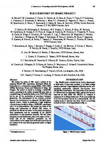
DEVELOPMENT OF ITEP-TWAC INFRASTRUCTURE Experimental area of ITEP-TWAC facility (Fig.1) includes now five zones of beam utilizing. Two of them are secondary beams of internal targets installed in second and third periods of U10 lattice. Two another’s are fast extracted beams from U10 ring to the target hall and to the building for medical applications. The 25 MeV beam of linac I2 is used in parallel for both injection to synchrotron U10 and different applications.
INTRODUCTION The ITEP-TWAC Facility runs in three operation modes accelerating protons up to the energy of 9.3 GeV, accumulating nuclei at the energy of 200-300 MeV/u and accelerating ions and nuclei up to the energy of 4 GeV/u. The total operation time of machine in 2007 is 3936 hours (in 2006 – 3088 h), divided between operation modes as the following: 2268 h of protons acceleration, 828 h of carbon nuclei accumulation, 648 h of carbon nuclei acceleration up to relativistic energies. Distribution of ITEP-TWAC between different research fields and applications in 2007-2008 is given in Table 1. Table 1. Operation of ITEP-TWAC for different subjects. Research fields and applications Relativistic nuclei physics Methodical research Physics of high density energy in matter Radiobiology Proton therapy Ion therapy Radiation treatment of materials Total
Beams p,C, … p,C, … C,Al,Fe,Zn p,C p C p,Fe,Sn,U
Operation time, hours 2007 2008 Req. 1030 1200 1000 1338 1500 2000 344 350 500 2520
2350
0 802
0 1200
6000
6034
6600
14500
Figure 1: Experimental area of ITEP-TWAC facility, green - in operation, yellow – in projecting.
5000
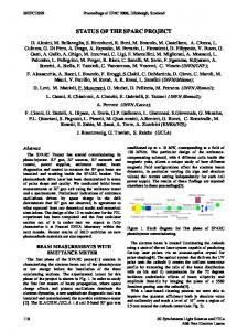
Extension of experimental area is planed on construction in twos slow extracted (SE) beams from U10 and UK rings as shown in Fig.1. First SE system for beam extraction from 203-blok of U10 ring (Fig.2) has been constructed and its testing is now going on. Second order resonance in vertical plane is exited by single sextupole for beam extraction to existing beam transfer lines which are used also for transfer of secondary beams generated in the 203 internal target.
It can be seen in this table the trend of machine operation time increase for applications of proton and ion beams in biology, medicine and radiation treatment of materials. The required beam time for users exceeds the possible one by factor of two. This discrepancy has to be eliminated in a result of machine infrastructure development and extension of its experimental area. *
This work is supported by ROSATOM
03 Cycling And Linear Accelerators
134
Proceedings of RuPAC 2008, Zvenigorod, Russia
in vacuum chamber by X-rays emitted from plasma spot on the target and ionizing residual gas.
Current pulse of ions from residual gas
Bunched beam of Fe-ions at the I-3 output
200 mA Figure 2: Slow extraction system of U-10 ring. Continuous extraction of carbon nuclei beam stacked in the U10 ring is shown in Fig.3. The working point of storage ring in this mode of beam extraction has been set near sextupole resonance so circulating particles scattered on molecules of residual gas and in stripping foil putting on unstable trajectories to be extracted.
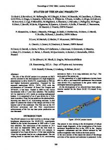
Fe-beam current at the extraction gap outlet Figure 4: Signals of Fe-ion beam generated in LIS. It can be seen in Fig.5 that Fe-ions of only few charge states of 14-16 are there at the head of beam pulse generated in LIS. Charge states of Fe-ions at the second vertex of the total beam current pulse are found in the expanded range of values from 12 to 16. The total number of Fe-ions of charge states from 12 to 16 is estimated by the value of ~1012, the number of Fe16+ ions at the head of the beam pulse is order of 5x10¹⁰.
Fe16+
Fe15+ Fe14+
Figure 3: Extraction carbon beam accelerated in the UK ring up to the energy of 200 MeV/u at repetition rate of 0.25 Hz using U10 ring as stretcher.
THE 100J CO2-LASER RUNNING FOR FeION BEAM PRODUCTION The new LIS optical scheme described in [4,5]. The typical laser radiation pulse at the free-running regime of laser operation is characterized by the sharp spike of 150 ns at the pulse front and a long low intensity radiation tail of 1-2 μs duration that contains up to 60% of the total laser pulse energy. Stretching in time the radiation energy investment to the target results in low-charge state ions domination in a generated ion beam and intensive evaporation of a target material. Typical signal of ion beam extracted from laser plasma in Fe-target and measured at the extraction gap outlet shows (Fig.4) the presence in the beam the high current pulse of charge particles passing through the extraction gap before Fe-ions. This forward pulse of ions is created
03 Cycling And Linear Accelerators
Figure 5: The Fe-ion species at the head of LIS beam. The first run of the 100J laser for heavy ions generation has been continued three week scheduled by 12 hours per day at repetition rate of 0.25 Hz. Most part of run time has been spent for with the Fe-beam and two last days with Al-beam. The laser has turned out more than 105 shots with high enough stability of pulse amplitude and energy distribution. Parameters of ion beam haven’t been so stable in time because of dynamic processes in the target caused by intensive evaporation of target material, and in the vacuum volume of plasma drift tube due to intensive adsorption of residual gas from surfaces bombarded by high current beam. 135
Proceedings of RuPAC 2008, Zvenigorod, Russia
depending on imperfection of the LIS target station which has to be improved. 3 mA, Fe-beam current at the I-3 output
Forward pulse overloading the I-3 buncher
Process of Fe-nuclei stacking
200 mA Stacked beam losses crossing the target and at circulation in vacuum of 10-8 Torr Figure 6: Current signals of total Fe-beam at the LIS extraction gap outlet and Fe16+-beam of 64 MeV at the I-3 linac output.
100 s
FIRST RESULTS OF Al AND Fe NUCLEI STACKING IN THE STORAGE RING U-10
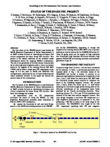
Figure 7: Stacking of Fe26+-nuclei in the U-10 ring..
CONCLUSION
The charge-exchange injection technique is used in the TWAC facility from 2002 for carbon nuclei stacking at particles energy of 200-300 MeV/u. Optimised staking process by scheme of C4+=>C6+ is characterised by stacking factor of k∝ ~ 70 and by maximum number of 4x10¹⁰ stacked carbon nuclei [4]. Parameters of stacking beams and injection system are listed in Tab.2. Energy of ions is high enough for its stripping to bare nuclei but the foil thickness provides 99% bare ion yield for C and Al and only 65-70% for Fe. Reduced yield of Fe-nuclei in stripping foil has to be compensated by decreasing of multiple Coulomb scattering and electron pickups increasing beam stacking efficiency. It was expected to get at experiments a little less efficiency of stacking for Fe-beam but a little more for Al-beam than it was obtained for C-beam.
The ITEP Accelerator Facility is now successfully in operation by more than 3000 hours yearly accelerating proton and ion beams and stacking carbon nuclei for physics experiments and radiation technologies. The nearest progress in the ITEP-TWAC project depends now on the Laser Ion Source commissioning with the master oscillator mode of the 100J CO2 laser operation required for a heavier ion beam generation with lionization potential of more than 1 kV. Experiments with Fe-nuclei stacking at the energy of 165 MeV/u indicates the unexpectedly high cross section of particles losses by electron pickups at the beam crossing the stripping foil and traversing large distance in vacuum of 10-8 Torr. The disagreement of experimental data with calculations has to be cleared in next experiments with stacking of Febeam at different conditions.
Table 2. Parameters for nuclei stacking Stacking ions Energy, MeV/amu Charge changing factor Injection rep. rate, Hz Stripping foil thickness, mg/cm2 Vacuum, Torr Acceptance filling Booster UK intensity, ppp Momentum spread, % Emittance, π mm⋅mrad Stacked beam intensity
12C
4→6
213 0.67 0.3
10→13 27Al
16→26 56Fe
265 0.77
165 0.615
REFERENCES [1] Yu.Saitov, B.Sharkov, H.Haseroth, et al. Journal of Russian Laser Reasearch, V.25, N.3 (2), p.205-210. [2] S.Kondrashev, A.Balabaev, K.Konukov, et al. Procidings of EPAC 2004, p.1402-1404. [3] N.Alexeev, et al., EPAC -2000, p.1283-1285. [4] N.Alexeev, D.Koshkarev, B.Sharkov, EPAC -2006, p.243-245 [5] B.Ju.Sharkov, NN..Alexeev, et al. EPAC -2008, MOPC122. [6] R.Anholt, S.A.Andrimonje et al. Phy.Rev.Lett. 53., 234 (1984) [7] J.Eichler, W.E.Meyerhof, Relitivistic Atomic Collisions, Academic Press, New York, 1995 [8] A.Ichihara, et al. Phys. Rev. A 49 (1994) 1875
0.25 1.5 (of mylar) 2x10⁻⁹ central peripheral ~2x10⁹ ~5x10⁷ ~1x10⁸ ±0.04 ~5 >4x10¹⁰ >5x10⁸ >2x10⁹
Main experimental results shown in Fig.7 are the following: Fe16+-ions are stripping in the foil with predicted probability, but Fe-nuclei loss rate in the target (Fig.7) and in vacuum of 10-8 Torr is order of magnitude higher than it was predicted by the theory [6-8]. The resulting process of Al-nuclei stacking have been as expected little differing from the C-nuclei stacking. The factor of Al-nuclei stacking was limited by the lack of optimization time and by injected beam instability 03 Cycling And Linear Accelerators
136