main goals of the project are: (1) the generation of a high brightness electron beam able to drive a self-amplified spontaneous free-electron laser (SASE FEL) ...
Proceedings of EPAC 2004, Lucerne, Switzerland
STATUS OF THE SPARC PROJECT* D.Alesini, S.Bertolucci, M. Bellaveglia, M.E.Biagini, R.Boni, M.Boscolo, M.Castellano, A.Clozza, G.Di Pirro, A.Drago, A.Esposito, M.Ferrario, D. Filippetto, V.Fusco, A.Gallo, A.Ghigo, S.Guiducci, M.Incurvati, C.Ligi, F.Marcellini, M.Migliorati, A.Mostacci, L.Palumbo, L.Pellegrino, M.Preger, R.Ricci, C.Sanelli, M.Serio, F.Sgamma, B.Spataro, A.Stecchi, A.Stella, F.Tazzioli, C.Vaccarezza, M.Vescovi, C.Vicario, INFN-Frascati F.Alessandria, A.Bacci, I.Boscolo, F.Broggi, S.Cialdi, C.DeMartinis, D.Giove, C.Maroli, V.Petrillo, M.Romè, L.Serafini, INFN-Milano D.Levi, M.Mattioli, G.Medici, P. Musumeci, INFN-Roma1 A. Cianchi, L.Catani, E.Chiadroni, S.Tazzari, INFN-Roma2 F.Ciocci, G.Dattoli, A.Doria, F.Flora, G.P.Gallerano, L.Giannessi, E.Giovenale, G.Messina, L.Mezi, P.L.Ottaviani, G. Parisi, L.Picardi, M.Quattromini, A.Renieri, C.Ronsivalle, ENEAFrascati S. De Silvestri, M. Nicoli, S. Stagira, Politecnico/Milano J.B. Rosenzweig, UCLA - Dept. of Physics and Astronomy D.H. Dowell, P.Emma, C.Limborg, D.Palmer, SLAC Abstract The aim of the SPARC project is to promote an R&D activity oriented to the development of a high brightness photoinjector to drive SASE-FEL experiments at 500 nm and higher harmonics generation. Proposed by the research institutions ENEA, INFN, CNR with the collaboration of Universita` di Roma Tor Vergata and INFM-ST, it has been funded in 2003 by the Italian Government with a 3 year time schedule. The machine will be installed at LNF, inside an existing underground bunker. It is comprised of an rf gun driven by a Ti:Sa laser to produce 10-ps flat top pulses on the photocathode, injecting into three SLAC accelerating sections. In this paper we present the status of the design activities of the injector and of the undulator. The first test on the RF deflector prototype and the first experimental achievements of the flat top laser pulse production are also discussed.
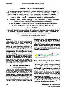
sections to feed a 14 m long undulator, see Fig.1. The main goals of the project are: (1) the generation of a high brightness electron beam able to drive a self-amplified spontaneous free-electron laser (SASE FEL) experiment in the green visible light and higher harmonics generation, (2) the development of an ultra-brilliant beam photoinjector needed for the future SASE FEL-based X-ray sources.
INTRODUCTION The SPARC project is an R&D activity to develop a high brightness photoinjector for SASE-FEL experiments funded by the Italian Government in 2003 with a 3 year time schedule. The installation of the machine at LNF will start on September 2004, and the first beam is expected on June 2006. The SPARC [1] complex is composed of an rf gun driven by a Ti:Sa laser producing 10-ps flat top pulses that hit on a photocathode. The out coming beam is injected into three SLAC accelerating
Figure 1.SPARC project layout. The project is also aiming at the development of sub-ps bunch length diagnostic, at the investigation of the beam emittance degradation due to the CSR in the dogleg magnetic compressor and the effects induced by the surface-roughness wake fields on the beam quality. In the next section of this report the status of the design activities of the injector and undulator is presented. In the
399
Proceedings of EPAC 2004, Lucerne, Switzerland following sections the first test results on the SPARC RF deflector are described and finally those obtained in the flat top laser pulse production are also presented.
SPARC PHOTOINJECTOR WORKING POINT OPTIMIZATION
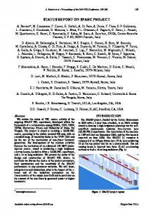
corresponds to a working point with 1.1 nC and a pulse length of 10 psec.The overall result is the reduction of the FEL-SASE saturation length from 12 to 9 m at 500 nm wavelength, see Fig. 2-3. Table 1 – Injector Parameters ELECTRON BEAM
The beam current required by the FEL experiment pushes the injector design towards the limits of the stateof-the-art for what concerns pulse charge and pulse shape. The design goal of the SPARC accelerator is to provide a 155 MeV bunch with less than 2 µm for the projected emittance and less than 1 µm for the slice emittance. The SPARC FEL operates in the diffraction dominated range and peak current, which, in the range of the diffraction dominated SPARC FEL the beam current is a key parameter for shortening the FEL gain length. Once including possible errors in the undulator system the analysis [2] of the SPARC-FEL operation shows that in order to leave a significant contingency margin to ensure full saturation and testing of harmonic generation a safer parameter set requires a beam having 100 A in 50% of the slices with a slice emittance ≤1 µm. For this purpose a new optimization, with Start-to-End simulations and parametric sensitivity studies aiming to reduce the FEL saturation length, was performed [3].
Electron Beam Energy (MeV) Bunch charge (nC) Repetition rate (Hz) Cathode peak field (MV/m) Peak solenoid field @ 0.19 m (T) Photocathode spot size (mm, hard edge radius) Central RF launch phase (RF deg) Laser pulse duration, flat top (ps) Laser pulse rise time (ps) 10%→90% Bunch energy @ gun exit (MeV) Bunch peak current @ linac exit (A) Rms normalized transverse emittance @ linac exit (mm-mrad); includes thermal comp. (0.3) Rms slice norm. emittance (300 µm slice) Rms longitudinal emittance (deg.keV) Rms total correlated energy spread (%) Rms incorrelated energy spread (%) Rms beam spot size @ linac exit (mm) Rms bunch length @ linac exit (mm)
A 155 1.1 1-10 120 0.273 1.13 33 10 1 5.6 100 80 1015 > 10 > 0.7
LASER TEMPORAL PULSE SHAPING
8 1 .10 ) 7 W1 .10 ( . 6 1 10
r 1 .105 e . 4 w1 10 o 1 .103 P 100
10 1 0.1
0
2
4
6
8 Z (m)
10
12
14
16
Figure 3: Power vs. z for the SPARC FEL, from GENESIS (final step in STE) simulation. The best result was obtained with a scaling approach [4] in which more charge is launched from the cathode. The configuration that gives the minimum emittance
The need to minimize nonlinearities in the space charge field of the electron bunch, in particular during the early stages of acceleration from the photo-cathode surface, leads to the needs of shaping the temporal profile of the laser pulse as it strikes the photo-cathode - the required shape is a uniform intensity distribution in time, often termed a flat-top time distribution. Beam dynamics simulations show that flat-top profile should exhibit very sharp edges in the head and tail of the pulse. The associated rise times must be at least shorter than 1 ps, with 0.5 ps being a desirable optimum value In collaboration with the Milano Politecnico ultra fast laser laboratory, a series of tests have been performed to demonstrate the fessibility of the pulse shaping with the
400
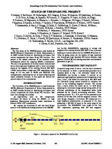
Proceedings of EPAC 2004, Lucerne, Switzerland Dazzler crystal. The preliminary results are of great interest to the SPARC laser pulse shaper design [5]. The obtained temporal intensity was measured by sampling the flat top pulse with the 20 fs reference pulses, delayed varying the optical path length by a translation stage with 100 nm resolution. The very short reference pulse assures a highly precise measurement of the shaped pulse. An interferometric filter was used to reduce the bandwidth of the incoming pulse. The measurements indicated that the acoustic optic crystal could produce pulse with duration up to 12 ps. Figure 4 reports the measurement of shaped intensity profile that approach the required pulse for SPARC photoinjector. As shown in the plot, the pulse rise and fall time is less than 0.7 ps and the ripple peak to peak is less than 20% and the pulse’s duration is thereabouts 11 ps FWHM. These preliminary results are very promising for producing the flat top temporal profile required in the SPARC photoinjector
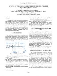
Figure 5: Schematic SPARC measurement layout for high energy beam characterization.
Figure 6: Deflector alluminum prototype and measurement setup. The results of the bead pull tests on the field profile of the rf deflector π-mode reveal a good level of magnetic field flatness.
CONCLUSIONS
Figure 4: Cross-correlation of the output shaped pulse in double-pass configuration.
RF DEFLECTOR DESIGN & TESTS The characterization of the longitudinal and transverse phase space of the beam provided by the SPARC photoinjector at 150 MeV is a crucial point to establish the performance quality of the photoinjector itself. By means of an RF deflector it is possible to measure the bunch length: the longitudinal beam distribution can be projected along a transverse coordinate and the image is collected on the screen. Using the orthogonal transverse coordinate distribution, both the horizontal and vertical beam emittances can be measured with the quadrupole scan technique. With the combination of the RF deflector and a dispersive system the longitudinal beam phase space can be completely reconstructed, (flag location FD2). The schematic layout of the measurement is reported in Fig.5. An aluminum cold test model of the 5cell π-mode rf deflector has been manufactured to LNF specifications and tested (Fig. 6) at the University of Rome “La Sapienza” by members of the SPARC team.
The SPARC project has been approved by the Italian Government and funded in June 2003 with a schedule of three years. After the first year the project has been fully defined, the major components ordered and promising tests on laser pulse shaping with Dazzler and RF deflector for beam diagnostics performed. The installation of the system will start in January 2005.
REFERENCES [1] SPARC Project Team, Sparc Injector TDR www.lnf.infn.it/acceleratori/sparc/ [2] M. Biagini et al., Beam Dynamics Studies for the SPARC Project, Proc of PAC 2003 [3] M. Ferrario, et al., “SPARC Photoinjector Working Point Optimization, Tolerances and Sensitivity to Errors”, these Proceedings [4] J.B. Rosenzweig and E. Colby, A d v a n c e d Accelerator Concepts p. 724 (AIP Conf. Proc. 335, 1995) [5] C. Vicario, et al., “Laser Temporal Pulse Shaping Experiment for SPARC photoinjector” [6] C. Vaccarezza, et al., “6D Phase Space Characterization of the SPARC Beam
401