163
A. Renieri et al. / Proceedings of the 2004 FEL Conference, 163-166
STATUS REPORT ON SPARC PROJECT A. Renieri*, M. Carpanese, F. Ciocci, G. Dattoli, A. Di Pace, A. Doria, F. Flora, G.P. Gallerano, L. Giannessi, E. Giovenale, G. Messina, L. Mezi, P.L. Ottaviani, S. Pagnutti, G. Parisi, L. Picardi, M. Quattromini, G. Ronci, C. Ronsivalle, E. Sabia, M. Sassi, A. Zucchini, ENEA, Centro Ricerche Frascati, C.P. 65, 00044 Frascati, Italy D. Alesini, M. Bellaveglia, S. Bertolucci, M.E. Biagini, C. Biscari, R. Boni, M. Boscolo, M. Castellano, A. Clozza, G. Di Pirro, A. Drago, A. Esposito, M. Ferrario, D. Filippetto, V. Fusco, A. Gallo, A. Ghigo, S. Guiducci, M. Incurvati, C. Ligi, F. Marcellini, M. Migliorati, C. Milardi, L. Palumbo, L. Pellegrino, M. Preger, P. Raimondi, R. Ricci, C. Sanelli, M. Serio, F. Sgamma, B. Spataro, A. Stecchi, A. Stella, F. Tazzioli, C. Vaccarezza, M. Vescovi, C. Vicario, M. Zobov, INFN-Frascati, Italy F. Alessandria, A. Bacci, I. Boscolo, F. Broggi, S. Cialdi, C. De Martinis, D. Giove, C. Maroli, V. Petrillo, M. Romè, L. Serafini, INFN-Milano, Italy D. Levi, M. Mattioli, G. Medici, P. Musumeci, INFN-Roma1, Roma, Italy L. Catani, E. Chiadroni, S. Tazzari, INFN-Roma2, Roma, Italy C.J. Bocchetta, M. Danailov, G. D'Auria, M. Ferianis, Elettra, Trieste, Italy A. Cianchi, A. D'Angelo, R. Di Salvo, A. Fantini, D. Moricciani, C. Schaerf, Università di Roma Tor Vergata, Roma, Italy S. Reiche, J.B. Rosenzweig, G. Travish, UCLA, Los Angeles, CA, USA D.H. Dowell, P. Emma, C. Limborg, D. Palmer, SLAC, Stanford, CA, USA Abstract* We review the status of FEL source activity of the ongoing SPARC FEL experiment, developed within the framework of a collaboration among ENEA, CNR, INFN, INFM, Sincrotrone Trieste and University of Rome Tor Vergata. The project is aimed at realising a SASE-FEL source, operating in the visible (around 500 nm), with an extended range of tunability down to the VUV (100 nm) by the use of the mechanism of non-linear harmonic generation. The development of the relevant activities foresees the realisation of an advanced 150 MeV photoinjector source, aimed at producing a high brightness electron beams, needed to drive a SASE-FEL experiment, and a 14 m long undulator. We present the status of the design and construction of SPARC FEL device. In particular we discuss the choice of the project parameters, their optimisation and the sensitivity of the SPARC performance to any parameter variation. We will show, using start-to-end simulations, what is the impact of the ebeam and of the undulator parameters on the characteristics of the output laser field and in particular on the amount of the non-linearly generated power at higher harmonics.
*
[email protected]
Available online at http://www.JACoW.org
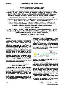
INTRODUCTION The SPARC project, funded by the Italian Government in 2003 with a 3 year time schedule, is an R&D activity aimed to develop a high brightness photoinjector for selfamplified spontaneous emission free-electron laser (SASE-FEL) experiments. The installation of the machine at LNF will start on September 2004, and the first beam is expected on June 2006. The SPARC [1] complex is composed of an RF gun driven by a Ti:Sa laser producing 10 ps flat top pulses that hit on a photocathode. The out coming beam is injected into three SLAC accelerating sections to feed a 14 m long undulator (Fig. 1).
Figure 1: SPARC project layout.
Single-Pass FELs
164
A. Renieri et al. / Proceedings of the 2004 FEL Conference, 163-166
The main goals of the project are: 1. the generation of a high brightness electron beam able to drive a SASE-FEL experiment in the green visible light and higher harmonics generation; 2. the development of an ultra-brilliant beam photoinjector needed for the future SASE-FEL based X-ray sources.
WORKING POINT OPTIMIZATION The beam current required by the FEL experiment pushes the injector design towards the limits of the stateof-the-art for what concerns pulse charge and pulse shape. The design goal of the SPARC accelerator is to provide a 155 MeV bunch with projected emittance lower than 2 µm and slice emittance lower than 1 µm. The SPARC FEL operates in the diffraction dominated range and peak current is a key parameter for shortening the FEL gain length. Once including possible errors in the undulator system (see next section), the analysis of the SPARC FEL operation shows that, in order to leave a significant contingency margin to ensure full saturation and testing of harmonic generation, a safer parameter set requires a beam having 100 A in 50% of the slices with a slice emittance ≤1 µm. For this purpose a new optimization was performed, with start-to-end simulations and parametric sensitivity studies aiming to reduce the FEL saturation length. The best result was obtained with a scaling approach [2] in which more charge is launched from the cathode. The configuration that gives the minimum emittance corresponds to a working point with 1.1 nC and a pulse length of 10 ps. The overall result is the reduction of the SASE-FEL saturation length from 12 to 9 m at 500 nm wavelength. The beam characterization is shown in Fig. 2, while FEL power as a function of z as obtained with the GENESIS code is reported in Fig. 3. In Tab. 1 and 2 the final parameter sets are reported.
Figure 3: FEL power longitudinal evolution (λu = 2.8 cm, K = 2.1413, I = 110 A). Table 1: Injector parameters. ELECTRON BEAM Electron beam energy (MeV) Bunch charge (nC) Repetition rate (Hz) Cathode peak field (MV/m) Peak solenoid field @ 0.19 m (T) Laser spot size, hard edge radius (mm) Central RF launch phase (deg) Laser pulse duration, flat top (ps) Laser pulse rise time 10%→90% (ps) Bunch energy @ gun exit (MeV) Bunch peak current @ linac exit (A) RMS normalized transverse emittance @ linac exit (mm-mrad); includes thermal comp. (0.3) RMS slice norm. emittance (300 µm) RMS longitudinal emittance (deg.keV) RMS total correlated energy spread (%) RMS uncorrelated energy spread (%) RMS beam spot size @ linac exit (mm) RMS bunch length @ linac exit (mm)
155 1.1 1-10 120 0.273 1.13 33 10 1 5.6 100 10 > 0.7
165
A. Renieri et al. / Proceedings of the 2004 FEL Conference, 163-166
The SPARC project foresees the possibility of extending the tunability range by exploiting the non-linear generation of higher order harmonics. The understanding of the mechanism underlying such a process has required a strong effort involving analytical and numerical means [3] and, as to the SPARC proposal, it has been shown that it is possible to obtain a significant amount of coherent power at higher order harmonics, which guarantees a brightness of third (170 nm) and fifth (100 nm) harmonic two orders of magnitude only below the fundamental.
0.010
0.005 0.000 -0.005
-0.010 0
109
8
10
12
14
λ=496.89 nm
108 107 106 105
3rd 5th
104 103 102 101 100
Fm δ
Fp
6
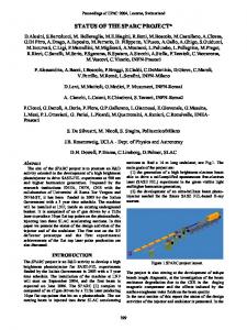
Figure 5a: Longitudinal on axis field variation along the six undulator sections due to the induced flexure.
power (W)
UNDULATOR SYSTEM
δ'
4
Z
In this type of FEL one of the most significant problems is that of reaching a good level of mechanical precision along the whole length of the undulator, which is a flexible structure. It is therefore evident that one of the first effects to be included in the optimization of the device is that of bending of the undulator section due to the magnetic and gravitational forces (Fig. 4). The variations of the longitudinal profile will be in turn responsible of magnetic field variations, which will provide a kind of inhomogeneous broadening and thus a gain reduction along with an increase of the saturation length. Fp
2
10−1 10−2 10−3
z
Fm
The problem of understanding the undulator bending effects on the SASE-FEL dynamics has been considered by merging two different points of view: a) a typical engineering approach [4], according to which we have defined the maximum bending as a function of the attractive forces and of the Young modules of the relevant materials; b) a method based on dynamical simulations [5][6], which have been able to evaluate the effects of a given flexure on the laser performances. An example of the effects due to the profile variations on the final laser power and on the subharmonics is given in Fig. 5, which shows how such an effect may become significant for values of the maximum deflection above 10 µm. This example yields just an idea of the problems arising within the study of the optimization of the device. There are indeed other effects which cannot be considered by their own and should be combined with the others, as e. g. those associated with the fact that the surface of the undulator poles assembly may not be perfectly parallel. This fact may combine with possible misalignments between undulator sections and it may induce a further gain reduction (Fig. 6), which has been accurately modelled [6].
0
1
2
3
4
5
6
7
8
9 10 11 12 13
Z (m)
Figure 5b: Effect of the induced flexure on the power evolution of the fundamental and higher order harmonics (solid: no flexure, dots: 10 µm maximum flexure in the centre; Prometeo code). 109
λ=496.89 nm
108
power (W)
Figure 4: Flexure of the undulator upper and lower faces induced by the attractive magnetic forces and the gravity.
107 106 105
3rd 5th
104
3rd
103 102
5th
101 100
10−1 10−2 10−3
0
1
2
3
4
5
6
7
8
9 10 11 12 13
Z (m)
Figure 5c: As in Fig. 5b for 50 µm maximum flexure (Prometeo code).
Single-Pass FELs
166
A. Renieri et al. / Proceedings of the 2004 FEL Conference, 163-166
109
power (W)
108 107
Fluorescent screen for Electron detection
106 105 104 103 102 100 10−1
0
1
2
3
4
5
6
7
8
Chamber length L=20cm
Radiation deflecting mirror
δ=0 µm, δ=5 µm, δ=25 µm, δ=50 µm, δ=100 µm,
101
10−2 10−3
CCD camera
Channel for wake fields suppression
λ=496.89 nm
To the vacuum
9 10 11 12 13
Z (m)
Figure 6: Effect of undulator faces misalignment on the laser power for different values of the maximum flexure δ (Prometeo code).
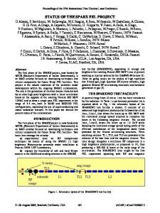
OPTICAL DIAGNOSTICS The diagnostic layout is shown in Fig. 7; a diagnostic chamber is positioned in correspondence of each undulator section. Through these chambers the FEL radiation is extracted and transported up to a measurement station placed at the ending part of the FEL.
Strip-Line
Three positions movement
Figure 8: Diagnostics chamber. A non-interceptive diagnostics, which will be tested at a later stage of the SPARC project, is based on the interaction between the electron beam and a metal grating. It has been shown that such a device is capable of providing quantitative information about the longitudinal bunch profile from the power spectrum of the emitted coherent spontaneous radiation [7].
CONCLUSIONS The SPARC project has been approved by the Italian Government and funded in June 2003 with a schedule of three years. After the first year the project has been fully defined and the major components have been ordered.
REFERENCES C U
C U W
C U W
C U W
C U W
U W OB
Figure 7: Diagnostic layout. U: undulator sections; C: diagnostic chambers; W: workstations for the analysis of the radiation from each undulator; OB: optical bench. The study and the design of the diagnostic chamber foresee a series of conditions to be fulfilled. Among them the most significant one is due to the reduced space available for its installation. The distance between the different undulator sections is about 36 cm and within such a space it will be necessary to allocate, along with the diagnostic chamber, the quadrupoles for the electron focusing on the horizontal plane. The schematic layout of the diagnostic chamber is shown in Fig. 8. The diagnostic chamber will host “pop-up” mirrors to extract the FEL radiation as well as electron diagnostics, alignment screens based on transition radiation and all necessary ports to connect to the vacuum pumping system.
MOPOS27
[1] SPARC Project Team, “SPARC Injector TDR”, (www.lnf.infn.it/acceleratori/sparc). [2] J.B. Rosenzweig and E. Colby, “Advanced Accelerator Concepts”, AIP Conf. Proc. 1995, Vol. 335, p. 724. [3] G. Dattoli, L. Giannessi, P.L. Ottaviani and A. Torre, J. Appl. Phys. (2004); G. Dattoli, these proceedings. [4] A. Zucchini, “Considerazioni relative alla flessione del supporto e dei magneti a causa del campo magnetico”, SPARC Tech. Note 03/007 (www.sparc.it). [5] F. Ciocci, G. Dattoli, L. Mezi and P.L. Ottaviani, “The effect of the magnetic deflection on the FEL evolution:a dynamical point of view”, SPARC Tech. Note 03/005 (www.sparc.it). [6] F. Ciocci, G. Dattoli, L. Mezi and P.L. Ottaviani, “Angular Tolerances in the SPARC undulator”, SPARC Tech. Note 03/008 (www.sparc.it). [7] G. Doucas, M.F. Kimmitt, A. Doria, G.P. Gallerano, E. Giovenale, G. Messina, H.L. Andrews, J.H. Brownell, “Determination of longitudinal bunch shape by means of coherent Smith-Purcell radiation”, Phys. Rev. Special Topics – Accelerators and Beams Vol. 5, 072802 (2002).