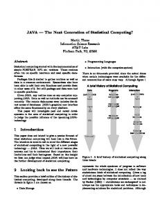
developed by a subgroup of JAIN, called the Java Call Control (JCC). .... Call Center environment, where a much greater degree of centralized processing and ...
Java Call Control Ravi Jain and Farooq Anjum Applied Research Telcordia Technologies 445 South St, Morristown, NJ 07960 {rjain,fanjum}@telcordia.com
Abstract Future telecommunications networks will consist of integrated packet-switched (IP and/or ATM), circuit-switched (PSTN) and wireless networks. Service providers will offer a wide portfolio of innovative applications over these integrated networks. Doing so rapidly and efficiently requires open network APIs, with a key API being that for call control as well as coordination and transactions. The JAIN community is defining an API for Java Call Control (JCC). The JCC API defines the interface for applications to initiate and manipulate calls. Note that in this context a call refers to a multimedia, multiparty, multi-protocol communications session. The JCC Edit Group of JAIN has defined the first version of the JCC API specification, which has been released in January 2001. This chapter describes the basic motivation and design of JCC 1.0.
1
Introduction
Future telecommunications networks will be characterized by new and evolving architectures where packet-switched, circuit-switched, and wireless networks are integrated to offer subscribers an array of innovative multimedia, multi-party applications. Equally importantly, it is expected that the process by which telecommunications applications are developed will change, and will no longer solely be the domain of the telecommunications network or service provider. In fact, in order to provide a broad portfolio of novel, compelling applications rapidly, service providers will increasingly turn to third-party applications developers and software vendors. Thus application development in the telecommunications domain will become more similar to that in the software and information technology in general, with customers reaping the benefits of increased competition, reduced time-to-market, and rapid leveraging of new technology as it is developed. To make this vision a reality it is necessary that future integrated networks offer application developers a set of standard, open Application Programming Interfaces (APIs) so that applications written for one vendor’s system can run on a different vendor’s system. This will enable the cost of applications development to be amortized, reducing the final cost to the customer. JAINTM is a community of companies led by Sun Microsystems under the Java Community Process that is developing standard, open, published JavaTM APIs for next-generation systems consisting of integrated Internet Protocol (IP) or Asynchronous Transport Mode (ATM), Public Switched Telephone Network (PSTN) and wireless
networks. These APIs include interfaces at the protocol level, for different protocols like MGCP1, SIP, and TCAP, as well as at higher layers of the telecommunications software stack.2 One of the key APIs being developed at the higher layers of the telecommunications stack is the API for defining the call model that the network offers the applications developer. The call model can be regarded as a specialized virtual3 machine for the development of telecommunications applications [1], with the API being the interface to that virtual machine. In this chapter we describe such an API developed by a subgroup of JAIN, called the Java Call Control (JCC). We stress here that the use of the phrase “call model”, which has traditionally been associated with the PSTN, does not imply that the work of the JCC Edit Group is focused on the PSTN. The charter of the JCC group is to develop an API that applies equally well to IP or ATM, PSTN, and wireless networks, as well as networks integrating these technologies. The development of open network APIs using Java represents an important departure from traditional methods by which the PSTN was made more open. In the past, AIN defined models that allowed creation of services outside switches, but typically these services were written in specialized languages, using specialized service creation environments, by specialized personnel. The benefits and potential pitfalls of using Java as a language for implementing telephony APIs have been discussed in [2], and for implementing protocols in [3]. We will not repeat these discussions here; the reader is referred to [2,3]. (Also note that a Java API to ATM is being developed by the Service Aspects and Applications Working Group of the ATM Forum.) However, we point out that aside from the benefits of the Java language itself (such as portability across different execution platforms), using Java allows the arsenal of Javabased technologies (Java Beans, Enterprise JavaBeans, etc.) to be applied to service development for telecommunications services. In addition, the growing number of tools, support utilities, development environments, and experienced programmers and designers available for Java potentially opens up large economies of scale in the service creation process. Finally, we have previously implemented a prototype call-processing platform in 100% pure Java that completes basic calls, performs advanced services, and also allows dynamic service deployment [1]. This chapter is organized as follows. In sec. 2 we will briefly survey existing call models and APIs, including AIN, JTAPI, and Parlay. In sec. 3 we describe the architecture and design of the JCC version 1.0 API and its components in some detail, focusing on a narrative explanation of its principal features rather than a line-by-line retelling of the specification. (Note that this material is not a substitute for the specification itself, which is the definitive source. The specification is available freely from the Sun Java web site, currently at http://java.sun.com/aboutJava/communityprocess/final.html.) In sec. 4 we illustrate the use of the JCC 1.0 API with two examples. The first example is a simple two-party call origination, while the second example illustrates the power of the JCC API in allowing standardized as well as customized event filtering during the invocation of applications. In sec. 5 we present a more detailed discussion of the relationship of JCC with JTAPI and Parlay call control, focusing on how the structure of JCC is designed to allow logical compatibility with these other APIs and the industry segments that the three APIs address. Finally in sec. 6 we end with some brief concluding remarks.
1
A list of acronyms is given at the end of this chapter Many of the product and service names mentioned in this paper are trademarks or service marks of their respective owners. 3 Not to be confused with the Java Virtual Machine (JVM). The virtual machine we refer to here is offered to the application by the software layer implementing the API. There may be a JVM below this layer if the application is written in Java.
2
2
2
Call models and APIs
The JCC API defines a programming interface to next-generation converged networks in terms of an abstract, object-oriented specification. As such it is designed to hide the details of the specifics of the underlying network architecture and protocols from the application programmer to the extent possible. Thus the network may consist of the PSTN, a packet (IP or ATM) network, a wireless network, or a combination of these, without affecting the development of services using the API. The API is also independent of network signaling and transport protocols. Thus the network may be using various call control protocols and technologies, for example, SGCP, MGCP, SIP, H.323, ISUP, DSS1/Q.931, and DSS2/Q.2931, without the explicit knowledge of the application programmer. Indeed, different legs of a call may be using different signaling protocols and be on different underlying networks. It is assumed that the network will be able to notify the platform implementing the API regarding events that have occurred and the platform will be able to process the event as necessary and inform the application using the API. In addition, the application will be able to initiate actions using the API that the platform will translate into appropriate protocol signaling messages to the network. It is the job of the platform to interface to the underlying network(s) and translate API methods and events to and from underlying signaling protocols as it sees fit. We stress that this translation is vendor-specific and is not specified by the API; thus different platform vendors may differentiate and compete based on the attributes (e.g. performance) of their translation. Traditionally, the word “call” in the PSTN evokes associations with a two-party, point-to-point voice call. In contrast, in this chapter and within the JAIN JCC Edit Group, we use the word call to refer in general to a multimedia, multiparty, multi-protocol communications session over the underlying integrated (IP, ATM, PSTN, wireless) network. By “multi-protocol” we mean here that different legs of the call, representing the logical connection to individual parties of the call, may be affected by different underlying communications protocols over different types of networks. Thus one leg of the call may be affected using the H.323 protocol [4], another via SIP [5], and a third via traditional PSTN signaling protocols like ISUP [6]. JCC can be used to set up multimedia sessions, provided they can be modeled using the abstractions provided by the JCC API. Note however, that JCC is not intended to provide fullfledged control of multimedia streams, such as synchronization facilities, control of different substreams, etc; these would be provided by additional packages built on top of JCC. Several call models and associated APIs have been developed in the past, including Advanced Intelligent Network (AIN) [7], Java Telephony API (JTAPI) [8, 2], and Telephony API (TAPI) [9]. While there are important differences among these call models, reflecting the architecture or application for which they were intended, their overall goal is generally similar: to initiate, control and manipulate calls, and to facilitate the development of applications that execute before, during or after a call. Rather than select any one particular call model, we believe it is worthwhile to learn from the experience gathered by the different communities that have developed existing call models, and develop a generic call model suitable for integrated next-generation networks. For example, the AIN call model was designed to allow applications to be developed for the PSTN. Thus the AIN call model implicitly assumes a specific distributed architecture where telephone switches perform the basic call processing functions. It is assumed that value-added services (e.g. toll-free number translation, time-of-day call routing etc.) are executed, before or during calls, by a specialized Service Logic Execution Environment (SLEE) like the Service Control Point (SCP). In contrast, JTAPI focuses on call processing and applications for a Private Branch Exchange (PBX) or Call Center environment, where a much greater degree of centralized processing and control is the norm.
3
Thus unlike AIN, JTAPI contains no facilities for suspending execution of call processing and invoking applications during call setup or mid-call. On the other hand, unlike AIN, JTAPI offers convenient, object-oriented abstractions for call manipulation, which facilitate the rapid development of objectoriented applications. A survey of all existing call models we have considered is outside the scope of this chapter. In the following subsections we briefly review three existing call models and APIs that are especially relevant to our efforts, namely AIN, JTAPI and Parlay. 2.1
Advanced Intelligent Network (AIN)
In terms of the service creation process, the AIN architecture represented an important advance when it was introduced. AIN separated service development from switching, allowing service logic to be developed more quickly and placed in specialized network elements attached to databases, e.g. the Service Control Point (SCP), while switches could be optimized for speed and efficiency. To do this, AIN introduces a call model that consisted essentially of two major elements. The first element is a pair of finite state machines representing the progress of a call as it is processed at the originating and terminating switch respectively. The second is the concept of triggers. Triggers can be defined at specific states of the originating or terminating switch’s finite state machine (FSM). When call processing reaches a state in the FSM where a trigger is defined and enabled, processing is suspended and a program (called service logic) executing at a remote network element like the SCP is invoked; call processing is resumed once the service logic completes execution. Note that the definition of the AIN call model can be regarded as switch-centric, in the sense that the fundamental activity is seen as call processing in the switch, while the service logic (which is not even dignified by being called an application program) is viewed as an ancillary activity. The application programmer must understand the details of the originating and terminating FSMs and interact with call processing at pre-specified states in the FSMs. There is no explicit abstraction offered to allow the programmer to manipulate entire calls, or legs of a call, or the principal logical entities in the call (e.g. the calling or called party’s address or phone number), and certainly not in any object-oriented fashion. Enhancements built around AIN (e.g. ITU’s Connection View [10]) offer facilities for modeling and manipulating calls, but these are also quite limited; for instance, at present, multi-party calls of more than three parties cannot be handled. Nonetheless, the AIN FSMs do capture the critical stages of call processing and states where it would be useful for application programs to intervene. 2.2
Java Telephony API (JTAPI)
The Java Telephony API (JTAPI) [8] is a portable, object-oriented interface for Java-based computertelephony applications. In the following, a “call” refers to a communications session among two or more parties; each party is informally said to be participating in one “leg” of the call. Thus a call has as many call legs (or connections) as the number of parties in the call. JTAPI is expressed in Java and defines a core call model to support basic call setup, and a number of extensions, mostly designed to model call center features, multi-party conference calls, call routing, etc. The core model consists of a few telephony classes and their relationships, as shown In reply to: Figure 1Figure 1. Each object in the figure corresponds to a physical or a logical entity in the telephone world. The Provider is an abstraction of a telephony service provider. A Provider class manages Call objects, representing calls at various stage of progress. (Note that in the description of JTAPI, as in the rest of this paper, capitalized words such as “Call” refer to specific objects in a model or API, while their lower-case counterparts such as “call” refer to the generic underlying concept such as a communication session.)
4
A Provider maintains a collection of static Terminal and Address objects in its domain. Terminal objects represent the physical endpoint of a call, while Address objects are logical endpoints. Notice that each Address can be associated with multiple Terminals and vice versa, reflecting the standard configuration for a call center. The Call, Connection, and Terminal Connection objects are created dynamically, on a per-call basis. The Call object models the state and operations of the call as a whole, i.e., the communications session among the different parties. Each leg of the call is separately modeled by means of the Connection object. More precisely, the Connection object models the state and operations of the logical association between a Call and a particular Address. Finally, a Terminal Connection represents state and operations of the logical relationship between one Connection and one Terminal object.
Applications Java Telephony API Provider Physical Logical Call Connection
Connection
Terminal Connection
Terminal Connection Address
Address
Terminal
Terminal
Figure 1: Objects in the JTAPI model
The state of a telephone call is maintained by finite state machines associated with Call, Connection and Terminal Connection objects (e.g., when a call is answered by the called party, the originating Connection object moves to the CONNECTED state). The complete definition of the state machines is part of the published JTAPI specifications [8]. It is clear from this brief description that JTAPI overcomes several of the limitations of AIN mentioned earlier. JTAPI offers the programmer clear, explicit abstractions for manipulating calls and the logical entities in a call. The API is object-oriented, and draws upon the advantages of Java by using inheritance for extensibility. The state of a call (maintained largely in the Connection object FSM) is encapsulated so that it can be manipulated only via accessor methods. JTAPI uses Java exceptions and the Java events model for reporting changes in state as well as other events of interest to the application. Nonetheless, JTAPI also has some drawbacks. The first is that the FSM in the Connection object is not as rich and detailed as AIN’s, and even with the call control extension package cannot represent all the states of call processing that AIN does. Thus not all the points in the call that may be of interest to applications are modeled. The second is that JTAPI does not contain any mechanism similar to AIN triggers, i.e., no mechanism to suspend call processing at a defined state in the FSM, invoke an application, and return results. Finally, JTAPI seems to be oriented towards providing support for developing applications in two types of scenarios: (1) where applications run on a single platform (e.g. a PBX); and (2) where applications run
5
on a platform that is “horizontally partitioned”, i.e., the higher layers of software (the application and the JTAPI layer) communicate via Java Remote Method Invocation (RMI) [11] with the lower layers over a network. Also, in JTAPI a Provider is assumed to be in control of all the legs of a call (they all hang off the same Call object managed by the Provider). While this assumption may add to the convenience of managing a centralized call center, it is not realistic in the broader setting of integrated next-generation networks. As we will describe in later sections, the JCC API is attempting to build upon the best aspects of JTAPI and AIN while avoiding their drawbacks. This is possible because JCC deployment is not necessarily switch-bound. It is thus possible to extend JTAPI-style call control beyond the traditional call center boundaries, while supporting AIN-style third-party service invocation. 2.3
Parlay
Parlay is a multi-vendor forum founded in 1998 to specify open APIs. Initially membership was closed, with 5 member companies in Phase 1 and 11 in Phase 2, but with Parlay 3.0 it has been opened. The Parlay 3.0 specification for call control is expected in mid-2001. The Parlay API describes two sets of interfaces: Framework Interfaces, which provide for the common functions that are required to enable services to work together in a coherent fashion, and Service Interfaces, which provide for the common functions that deliver whole complex services or subcomponents of services (micro-services.) The Service Interfaces include the Parlay call control API. In Phase 1 of the API, the overall areas of focus were authentication, event notification, integrity management, OA&M, and service discovery. Phase 2 of the Parlay APIs expanded the scope to include IP network control, mobility, performance management, audit capabilities, and improved integrity. The plan for the next phase of Parlay includes generic charging/billing, policy management, and Virtual Home Environment (VHE). Clearly, the scope of Parlay is much larger than simply call control, but the Parlay call control API has received a great deal of attention. Each iteration of the Parlay call control API has undergone significant changes, and backward compatibility has not always been maintained. The design of JCC 1.0 was driven by a desire to minimize the incompatibilities between the Parlay call control API and the JCC API. We will discuss the relationship between Parlay, JTAPI and JCC APIs later in this chapter. 2.4
Java Call Control
The JCC Edit Group has developed an API that provides an interface to a generic call model that captures the essential aspects of existing call models. The API thus provides the applications programmer with a convenient and powerful abstraction for manipulating calls and managing the interaction between the application and calls. In addition, the API is extensible, so that as additional functions are required, they can be added incrementally and in a modular fashion to the API. To understand JCC it is helpful to understand the scope and context within which it is being defined. The JAIN standardization effort is organized in two broad areas: a Protocols Expert Group (PEG) standardizing interfaces to PSTN and IP signaling protocols and an Application Expert Group (AEG) dealing broadly with the APIs required for service creation within a Java framework. Each Expert Group is organized as a collection of Edit Groups dealing with specific protocols or APIs. Telcordia has been active in several aspects of the JAIN effort, including providing critical input to the JAIN TCAP Edit Group within the PEG which is standardizing a Java interface to TCAP, as well as
6
being the Edit Lead company for the MGCP specification. Telcordia has also taken a lead position within the AEG; in particular, Telcordia is the Edit Group lead for the JAIN Edit Group standardizing interfaces for Java Call Control (JCC). Other member companies of the JCC Edit Group for JCC 1.0 are AePONA, British Telecom, IBM, Lucent, Motorola, Nortel Networks, Sun Microsystems and Ulticom. In addition, in order to align JCC with JTAPI and Parlay, Telcordia interacted extensively with member companies of these groups, in particular Ericsson and Siemens. The Java Call Control (JCC) Application Programming Interface (API) is a Java interface for creating, monitoring, controlling, manipulating and tearing down communications sessions in a converged PSTN, packet-switched, and wireless environment. It provides facilities for first-party as well as third-party applications, and is applicable to network elements (such as switches or Call Agents) both at the network periphery (e.g. Class 5 or end-office switches) and at the core (e.g. Class 4 or tandem switches). JCC allows applications to be invoked or triggered during session set-up in a manner similar in spirit to the way in which Intelligent Network (IN) or Advanced Intelligent Network (AIN) services can be invoked. JCC thus allows programmers to develop applications that can execute on any platform that supports the API, increasing the market for their applications. It also allows service providers to rapidly and efficiently offer services to end users by developing the services themselves, by outsourcing development, purchasing services developed by third parties, or a combination thereof. The API is not intended to open up telecommunications networks’ signaling infrastructure for public usage. Rather, network capabilities are intended to be encapsulated and made visible using object technology in a secure, manageable, and billable manner. This approach allows independent service developers to develop applications supported by the network without compromising network security and reliability. The API is specified in terms of a coherent collection of related and interacting objects that model different physical and logical elements involved in a session, and related functions. Applications interact with these objects via an object-oriented Listener paradigm. Note that the API is applicable to control of voice, data or multimedia sessions, and not just voice calls, but for convenience we often use the word “call” in the specification.
7
Figure 22: JCP and JCC inheritance relationship Java Call Processing (JCP)
Java Call Control (JCC)
The API is structured into the following three functional areas; this document describes only the first two. •
Elementary Call Control: JCP. The Java Core Package (JCP) package includes the very basic facilities required for initiating and answering calls. It is likely that the facilities offered by this package will be too elementary for many if not most carrier-grade deployments. However, as explained later, it represents an important conceptual cornerstone for unifying the call control APIs developed by the Java Telephony API (JTAPI), JAIN and Parlay expert groups. It also represents a simple first step of software that can then be implemented, tested, reused and logically extended to a full implementation of the Java Call Control API. • Core Call Control: JCC. The Java Call Control (JCC) package includes the facilities required for observing, initiating, answering, processing and manipulating calls, as well as to invoke applications and return results during call processing. Here a call is understood to include (but is not necessarily limited to) a multimedia, multiparty session over the underlying integrated (PSTN, packet and/or wireless) network. It is likely that the facilities offered by this package will suffice for implementing most, but not all, of the basic and value-added services offered by carriers. • Extended Call Control: JCAT. The Java Coordination and Transactions (JCAT) package includes facilities similar to JCC, but extended to provide finer granularity of call control. In particular, unlike JCC, JCAT enables all common AIN applications as well as other integrated voice/data and next-generation services. For all the packages above, applications may be executing on the switching platform itself (e.g. a softswitch or Call Agent platform) or in a coordinated, distributed fashion across multiple generalpurpose or special-purpose platforms. The JCC and JCP APIs define four objects, which model the key call processing objects manipulated by most services. These are a Provider, Call, Connection, and Address. Several of these objects contain finite state machines that model the state of a call, and provide facilities for allowing applications to register and be invoked, on a per-user basis, when relevant points in call processing are reached. The JCP and JCC APIs described in this document are intended to be consistent with the APIs issued by the JTAPI and Parlay groups. In the case of JTAPI, the JCP API represents an elementary call control package that forms the common base of both JCC and JTAPI; thus JCC and JTAPI are very consistent in this respect. In the case of Parlay, JCC is supposed to be the Java version of the Parlay API for call control as accepted by the JAIN Service Provider API (SPA) group that is standardizing Java instantiations of the Parlay API. However, as of this writing, the Java version of the Parlay call control API (i.e., JCC) is similar but, unfortunately, not functionally identical to the UML version of the
8
Multiparty Call Control Service package of the Parlay call control API; it is hoped that future revisions to the JCC and Parlay call control APIs will close this gap. We would like to remark here that the JCC API deliberately does not address the issue of how the API would be implemented in a distributed environment with multiple providers. This is left as something to be worked out by individual implementations. We do believe, however, that a distributed implementation of JCC is possible. In particular, our group has previously implemented a distributed version of enhanced JTAPI in the CitiTime[1] project and our experience shows that a similar implementation of JCC should be possible also.
3
Java Call Control Architecture
In this section we describe the design and structure of JCC 1.0. Note that this is intended as a general description only to provide an aid to understanding the specification, and is not a substitute for the specification itself, which is the definitive source. Also note that future versions of JCC may not necessarily be identical or compatible with JCC 1.0 or with the description given here, although of course efforts will be made to retain backward compatibility. 3.1
Service drivers and requirements
The design of JCC is driven by a set of service drivers, which are specified explicitly in each release of the specification document. In addition to supporting two-party and multi-party calls, for the first release, it is required that the API support: • Virtual private network (VPN): This is a corporate service that provides companies a way to link different sites with a uniform and private dialing plan, regardless of geographical boundaries. The main function of a VPN application is to translate dialed (VPN) numbers into a routable directory number (e.g. phone number). Thus a user need only dial, say “1 1212” and the application will translate this into the phone number of a remote site (say, “1 973 829 1212”). • Click-to-dial (CTD): CTD is a hybrid Internet/PSTN service that allows a terminal user browsing WWW pages to request a call setup by simply clicking a number or name displayed on the terminal. This service is particularly useful for providing catalogue shopping, banking or travel agent online services with the capability of letting a user speak to an agent using the telephone system. The functionality of user interaction has not been included in version 1.0 of the JCC specification in order to maintain separation of concerns. A separate Edit Group in JAIN is addressing user interaction. In combination with user interaction features many more services such as voice activated dialing, prepaid services etc. can also be provided. These services can be mapped into capabilities that must be made available via the API, and typically these capabilities are also required for numerous other applications. For example, VPN requires number lookup and translation capabilities during call setup; this facility is also required for toll-free calls. CTD requires interaction between heterogeneous network types as well as voice/data integration. Additional requirements defined for JCC include one that it support first-party as well as third-party call control. Here, as in JTAPI, a “first-party” call is one where the application or entity initiating the call is in control of a single address, whereas a “third-party” call is one where the application has control over two (or more) addresses. For example, a first-party call can be a call initiated directly by a user, using appropriate terminal equipment, via underlying signaling protocols appropriate for the network the user is
9
connected to. On the other hand, a third-party call could be a situation where an application program initiates a call to connect two (or more) users or end devices. Hence, in case of the third party scenario an application has control over and can interact with more than one endpoint simultaneously. An example is a hotel wake-up call service, where the application program rings the guest’s phone and connects him or her to an operator or automatic playback device. In general JCC will also be required to support most of the features available as AIN or switch-based features in the PSTN, such as call forwarding, call waiting, etc. In addition, it is explicitly a requirement to keep the JCC API in harmony with existing Java APIs for call control, in particular JTAPI (e.g. allowing third-party call control using mechanisms similar to JTAPI.) 3.2
Basic Components of the API
In this section we describes the basic objects of the API common to both JCP and JCC as well as the common design patterns to both packages. For both JCC and JCP, the API components consist of a related set of interfaces, classes, operations, events, capabilities, and exceptions. The API provides four key objects, which are common to JCP, JCC and more advanced packages. The four key objects are: • Provider: represents the “window” through which an application views the call processing. • Call: represents a call and is a dynamic “connection of physical and logical entities” that bring two or more endpoints together. • Address: represents a logical endpoint (e.g., directory number or IP address). • Connection: represents the dynamic relationship between a Call and an Address. The relationship among these objects is depicted pictorially in Figure 3Figure 3 for a two-party call. Multiple parties are represented – with no inherent limitations in the model -- simply by additional Connections and Addresses associated with a Call. In traditional telephony parlance, this model is “symmetric” in that there is no fundamental distinction at the highest level between originating and terminating parties of a call, and is a “full” model in the sense that the application, in principle, has a view of all parties of the call. (Of course, depending upon the deployment scenario, this view might not be complete or accurate at all times.)
Provider
Call
Connection
Connection
Address
Address
Figure 33: Object model of a two-party call
10
The purpose of a Connection object is to describe the relationship between a Call object and an Address object. A Connection object exists if the Address is a part of the telephone call. Connection objects are immutable in terms of their Call and Address references. In other words, the Call and Address object references do not change throughout the lifetime of the Connection object instance. The same Connection object may not be used in another telephone call. Provider Provider Listener Listener
Call Call Listener Listener
Connection Connection Listener Listener
Synchronous method calls
JCC API Java Events Connection Connection Provider Provider
Network or Platform
Call Call Connection Connection
Figure 44: API programming pattern using Java Listeners
3.2.1
Basic API patterns: Listeners and Factories
The basic programming pattern of the API is that applications (which reside “above” the API) make synchronous calls to API methods, i.e., the application invoking the method blocks until the method completes processing and returns. The platform or network element implementing the API can inform the application of underlying events (e.g. the arrival of incoming calls) by means of Java events. The application provides Listener objects corresponding to the events that it is interested in obtaining. In addition, the API also uses the Factory design pattern commonly used (and recommended) in Java. In brief, applications use a PeerFactory to obtain a Peer, which in Java nomenclature is “a particular platform-specific implementation of a Java interface or API”, i.e., a vendor's particular implementation of the API. Applications then use the Peer to obtain access to the Provider object. 3.2.2
Event and Listener inheritance diagrams
Since several objects in the API can generate events, which in turn can be trapped by different Listeners written by the application programmer, the Event and Listener objects are organized by inheritance. The inheritance diagrams are shown in Figure 5Figure 5. The ProviderEvent indicates any state change occurring in the JcpProvider, the CallEvent indicates state changes occurring in the JcpCall object while the ConnectionEvent indicates state changes in the JcpConnection object. These events are in turn reported to their corresponding listeners namely the ProviderEvent to the ProviderListener, the CallEvent to the CallListener and the ConnectionEvent to the ConnectionListener. Further a ConnectionEvent inherits from a CallEvent while the ConnectionListener inherits from a CallListener.
11
Event
Call Event
Events
Listener
Provider Event
Call Listener
Connection Event
Listeners
Provider Listener
Connection Listener
Figure 55: JCC and JCP Event and Listener inheritance diagrams
3.3
Java Core Package (JCP)
In this section we describe the basic components of JCP. JCP is the elementary Java package from which more advanced call control packages inherit. JCP provides, among others, a few key methods to support its primary features of placing and dropping calls. The JCP specification defines, for each method, the pre- and post-conditions of the method in terms of state transitions in these FSMs. 3.3.1
JcpProvider
A JcpProvider represents the software-entity that interfaces with a telephony subsystem. The telephony subsystem could be a PBX connected to a server machine, a telephony/fax card in a desktop machine or a networking technology such as IP or ATM. The JcpProvider object has a state machine associated with it as shown in Figure 6Figure 6 below. For the Provider FSM, the meanings of the states are as follows. • IN_SERVICE: This state indicates that the Provider is currently alive and available for use. • OUT_OF_SERVICE: This state indicates that a Provider is temporarily not available for use. Many methods in this API are invalid when the Provider is in this state. Providers may come back in service at any time; however, the application can take no direct action to cause this change. • SHUTDOWN: This state indicates that a Provider is permanently no longer available for use. Most methods in the API are invalid when the Provider is in this state. Applications have access to a method to cause a Provider to move into the SHUTDOWN state. A Provider is the entity that a call control application has to access in order to initiate the placement of a call. An incoming signal into a platform also contacts the Provider initially before any further action can take place. An application does not create a JcpProvider object directly but obtains access to one using the getProvider() method in JcpPeer interface. Since JCP is an elementary package that maintains the commonality between JTAPI and Java Call Control, the JcpProvider has a very primitive behavior. The behavior is evidenced by the methods on the JcpProvider. The JcpProvider has methods to allow the addition and deletion of the listeners on the Provider, to obtain the name and state of the JcpProvider, to shutdown the JcpProvider, to initiate a call by creating the JcpCall object as well as a method to return the object given an address string. Note that this object is expected to be a JcpAddress object corresponding to the address string given.
12
IN_SERVICE
SHUTDOWN
OUT_OF_SERVICE
Figure 66: JCP and JCC Provider Finite State Machine
3.3.2
JcpCall
A JcpCall is a transient object representing communication between two or more parties. Invoking the createCall() method on the JcpProvider creates this object for an outgoing call. For an incoming call, the platform creates this call due to the incoming network signals. The call and its associated connection and address objects describe the control and media flows taking place in some underlying physical communication network. Note that in JCC 1.0 a call may be controlled by any of the parties involved in the call, not just the originating connection, thereby causing the membership and state of the endpoints of the call to change. The JcpCall object represents an indirect relationship between the JcpProvider and the JcpAddress through the JcpConnection. (We will look at these other objects later.) The JcpCall maintains a reference to its JcpProvider for the life of that JcpCall object. The JcpProvider object instance does not change throughout the lifetime of the JcpCall object. The JcpProvider associated with a JcpCall is obtained via the getProvider() method on the JcpCall object. The JcpCall object has a state machine associated with it as shown in Figure 7Figure 7 below. For the JcpCall FSM, the meanings of the states are as follows. • IDLE: This is the state in which all calls begin. In this state, the JcpCall does not have any JcpConnections associated with it. • ACTIVE: A call with some current ongoing activity is in this state. In this state the JcpCall object must have one or more associated JcpConnections. • INVALID: This is the final state for any JcpCall object. In this state the JcpCall object must have zero JcpConnections associated with it. Further a JcpCall object in this state may not be used for any future action. The JcpCall object has five methods associated with it. Three of these methods are used to provide information about the JcpProvider associated with the JcpCall, the state of the JcpCall as well as the JcpConnections associated with this JcpCall. The other two methods exist in order to add and remove call listeners on the JcpCall object. IDLE
INVALID
ACTIVE
Figure 77: JCP Call object Finite State Machine
13
3.3.3
JcpConnection
A JcpConnection object describes the relationship between a JcpCall object and a JcpAddress object. This is also transient in that the object exists only as long as this connection on the call exists. Hence, a new JcpConnection object has to be created for every new connection that has to be set up on a call. Each JcpConnection has a state that describes the particular stage of the relationship between the JcpCall and JcpAddress. These states and their meanings as taken from the JCC specification are given below. Note the intentional similarity between this FSM and the FSM for the Connection object of the JTAPI Core API. • IDLE: This state is the initial state for all new Connections. Connections in the IDLE state are not actively part of a call, yet their references to the Call and Address objects are valid. Connections typically do not stay in the IDLE state for long, quickly transitioning to other states. • DISCONNECTED: This state implies that the connection is no longer part of the call, although its references to Call and Address still remain valid. A Connection in this state is interpreted as once previously belonging to this call. • INPROGRESS: This state implies that the connection object has been contacted by the origination side or is contacting the destination side. The contact happens as a result of the underlying protocol messages. Extension packages elaborate further on this state in various situations. • ALERTING: This state implies that the Address is being notified of an incoming call. • CONNECTED: This state implies that a Connection and its Address are actively part of a call. In common terms, two people talking to one another are represented by two Connections in the CONNECTED state. • UNKNOWN: This state implies that the implementation is unable to determine the current state of the Connection. Typically, methods are invalid on Connections that are in this state. Connections may move in and out of the UNKNOWN state at any time. • FAILED: This state indicates that a Connection to that end of the call has failed for some reason. One reason why a Connection would be in the FAILED state is because the party was busy.
UNKNOWN
* except FAILED or DISCONNECTED FAILED
IDLE
INPROGRESS
ALERTING
CONNECTED
DISCONNECTED
Figure 88: JCP Connection object Finite State Machine Three methods exist on the JcpConnection interface. These are used to obtain information about the JcpAddress and JcpCall associated with the JcpConnection as well as a method to obtain the state of the JcpConnection object.
14
3.3.3.1 Immutable connections A JcpConnection object is immutable, in the sense that over the lifetime of a JcpConnection object, the JcpConnection can be associated with only one JcpCall and one JcpAddress object. If any of these (JcpCall or JcpAddress) objects have to be changed a new JcpConnection object has to be created. Note that this implies that every time an address associated with a JcpConnection has to change such as in the case of call forwarding, redirection etc, a new JcpConnection object has to be created. The advantages of having an immutable JcpConnection are as follows: • Simpler FSM. If the Call and Address objects associated with a Connection object were allowed to change then it should be possible to transition from any state to the idle state when changing the association. • No additional events. If the JcpConnection object were mutable then additional events (such as ending address/call association, starting address/call association) would be required to let the application know when the association between the connection and the JcpCall or the JcpAddress object (or both) changes. The disadvantages of having an immutable JcpConnection are as follows: • Additional Connection object management effort. With immutable connections some extra effort is required in the creation and management of Connection objects. For example, consider party A calling party B and assume that the call has to be redirected to C. With immutable Connections, initially two JccConnections will exist at B (one modeling the terminating connection from A and the other modeling the originating connection to C), which would be merged and/or deleted once the call setup to C completes. On the other hand, with mutable Connections only one JccConnection need exist at B. Of course, this single JccConnection will need to have information about the originating party A. This is so that the association between the redirected party and the originating party can be made for the purpose of setting up the data path. When the call ends none of these JccConnections need be destroyed but could be reused. (Note, however, that this latter effect, i.e., object reuse, can be obtained by object pooling and is an implementation issue rather than a modeling issue. In fact, one could argue that the reuse of objects should not be made visible at the API level in order to free the programmer from object management chores and to allow the programmer a more abstract view of call processing.)
The issue of connection mutability was discussed extensively within the JCC Edit Group, and it was decided that on balance immutable connections were preferable. This is also in keeping with the practical experience of the JTAPI community. 3.3.4
JcpAddress
A JcpAddress is an object that represents an endpoint in a communication. This can represent a telephone number, email address etc. Every JcpAddress object is expected to have a corresponding string representation, which for example can be the telephone number. During the course of communication between two or more parties, address objects are related to Call objects via the Connection object. The state of the Connection object describes the current relationship between the Call and the Address. Each address object may be part of more than one call, and in each case, is represented by a separate Connection object. Since the endpoints of a call are not transient, the JcpAddress objects, which represent these endpoints, are also not transient. Further, any JcpAddress object is expected to belong to the domain of some JcpProvider. Thus every JcpAddress object has to have a JcpProvider associated with it. Based on this, 15
relative to a given JcpProvider two types of JcpAddresses are possible, namely local and remote. A JcpAddress is considered local relative to a given JcpProvider if it belongs to the JcpProvider’s domain and considered remote otherwise. The methods on a JcpAddress interface are very primitive and are used to obtain the name of the JcpAddress object and the JcpProvider object associated with the JcpAddress object. Note that the name of the JcpAddress object is expected to be the same as its string representation. 3.4
Java Call Control (JCC)
In this section we look at Java Call Control. The JCC API has the same four key objects as JCP, namely Provider, Call, Connection and Address. Since JCC inherits from JCP, each object may contain additional methods beyond those in JCP. We note that as for JCP, JCC Connection objects are immutable in terms of their Call and Address references. In other words, the Call and Address object references do not change throughout the lifetime of the Connection object instance. Note that the corresponding objects now have the Jcc prefix such as JccCall, JccConnection etc. 3.4.1
JccProvider
The JccProvider interface inherits from the JcpProvider interface. An important feature exhibited by the JccProvider not provided by JcpProvider is the ability to act as a factory for EventFilter objects. The function of EventFilter objects is to act as a filtering mechanism for Events. We will look at EventFilters in detail later. The other methods on the JccProvider allow the ability to add listeners to the various call control objects in order to detect state changes in these objects. 3.4.2
JccCall
The JccCall interface inherits from the JcpCall interface. The states of the finite state machine are the same in case of both the interfaces, but the JccCall object has an extra transition visible to the application4.The JCC Call object FSM is shown in Figure 9Figure 9. The JccCall interface exhibits additional behavior as compared to a JcpCall interface. Some of the important methods are createConnection(), routeCall() and release(). We next consider these methods briefly. As explained earlier, a JcpCall and hence a JccCall represent a call. A call in turn consists of many connections. In both JCC and JCP, an application wishing to initiate a call has to first create the object representing the call. This is achieved by invoking the createCall() method on the JccProvider interface. Note that a JcpCall object is returned by the JccProvider.createCall() method and this has to be cast to a JccCall object. The next step is to create the connections on the object representing the call by invoking the createConnection() method on the JccCall object. This method results in a new JccConnection object being created and associated with the JccCall and a given JccAddress object. First party calls, third party calls, call translation as well as call redirection can all be achieved by using different semantics associated with this method. In order to complete the call it has to be routed to the
4
It might appear that we have a violation of the inheritance contract here. This discussion is outside the scope of this chapter. However, we point out briefly that one consistent view is that the underlying FSM for JcpCall is fully connected but the API only exposes a subset of the transitions. Subsequently, JccCall does not add any transitions, but chooses to expose an additional transition. 16
endpoint. This can be achieved by invoking the routeConnection() method on the JccConnection object. We will consider this method later while discussing the JccConnection interface. The createConnection() method discussed above is used just to create a JccConnection object. The routeCall() method differs from the createConnection() method in that it not only creates a JccConnection object but also results in the JCC implementation initiating signaling in the network towards the endpoints of the call. Thus the successful invocation of the routeCall() method results in the call having been successfully routed to an endpoint. This method can be used for first party calls, third party calls, number translation as well as call redirection. The release() method is used in order to release the call thereby freeing up the resources used up in the network. This will cause the JccCall and the corresponding JccConnection objects to be destroyed.
IDLE
ACTIVE
INVALID
Figure 99: JCC Call object FSM
3.4.3
JccConnection
The JccConnection interface inherits from the JcpConnection interface. The important methods on a JccConnection interface are routeConnection(), answer(), release(), continueProcessing(), getXXXAddress(), getMoreDialedDigits() and selectRoute(). The JccConnection object has a different FSM from JCP. Note however, that the JCC Connection FSM is a refinement of the JCP Connection FSM (i.e., obtained by adding transitions or splitting states into multiple states). In particular, the states of the JccConnection FSM map in a one to one fashion with the states of the JcpConnection FSM except for the INPROGRESS and CONNECTED states of the JcpConnection FSM. These two states are divided into further substates in the JccConnection FSM. The FSM is shown in Figure 10Figure 10. The states are described as: • • • • •
IDLE: This state is the initial state for all new Connections. Such Connections are not actively part of a telephone call, yet their references to the Call and Address objects are valid. Connections typically do not stay in the IDLE state for long, quickly transitioning to other states. AUTHORIZE_CALL_ATTEMPT: This state implies that the originating or terminating terminal needs to be authorized for the Call. ADDRESS_COLLECT: In this state the initial information package is collected from the originating party and is examined according to the “dialing plan” to determine the end of collection of addressing information. ADDRESS_ANALYZE: This state is entered on the availability of complete initial information package/dialing string from the originating party. The information collected is analyzed and/or translated according to a dialing plan to determine routing address and call type. CALL_DELIVERY: On the originating side this state involves selecting of the route as well as sending an indication of the desire to set up a call to the specified called party. On the
17
• • • • • •
terminating side this state is involves checking the busy/idle status of the terminating access and also informing the terminating message of an incoming call. ALERTING: This state implies that the Address is being notified of an incoming call. CONNECTED: This state implies that a Connection and its Address is actively part of a telephone call. In common terms, two parties talking to one another are represented by two Connections in the CONNECTED state. SUSPENDED: This state implies that this connection object is suspended from the call, although it’s references to a Call and Address objects will still remain valid. DISCONNECTED: This state implies it is no longer part of the telephone call, although its references to Call and Address still remain valid. A Connection in this state is interpreted as once previously belonging to this telephone call. UNKNOWN: This state implies that the platform is unable to determine the current state of the Connection. FAILED : This state indicates that a Connection to that end of the call has failed for some reason (e.g. because the party was busy).
JCCConnection FSM Idle Idle
Authorise Authorise Authorize Authorize Call Call Call Call Attempt Attempt Attempt Attempt
Address Address Collect Collect
Failed Failed Unknown Unknown
Disconnected Disconnected
Address Address Analyze Analyze
CallDelivery CallDelivery
All All valid valid states states
Alerting Alerting
Connected Connected
Suspended Suspended
Figure 1010: JCC Connection object FSM When a call is to be placed by an application, the application creates a call object using the Provider. Following this one possible option for the application is to have the JccConnection created by invoking the JccCall.createConnection() method, as explained earlier. Once the JccConnection object has been created, the connection will have to be routed to the end point. This is accomplished by invoking the routeConnection() method on the JccConnection interface. As a result of this the implementation causes signaling messages to be sent out over the network if necessary (unless both the originating and destination end point are on the same JCC platform). The destination party answers the incoming call by invoking the answer() method. When either party wishes to disconnect the call, it invokes the release() method on the corresponding JccConnection object. For a two party call, the whole call is torn down when one of the parties hangs up; otherwise, the release() method on the
18
JccConnection results in only the corresponding leg of the call being disconnected. The rest of the call may proceed with the reduced number of parties. The method selectRoute() is intended to enable address translation. For example if A makes a tollfree call (where the destination number has a 1-800 prefix), the destination number will have to be translated to a routable number. The number translation application (registered beforehand as a listener) translates the number and returns control to the platform using the selectRoute() method. The method getMoreDialedDigits() is used by the application to instruct the platform to collect further address information (which may be in the form of digits or letters) and return this to the application. The platform is then expected to return only the additional information collected as a String. We will describe the continueProcessing method later in this same section when we discuss events. 3.4.3.1
Events and event blocking
As described earlier the finite state machine of the JccConnection object is a refinement of the finite state machine of the JcpConnection object. Further, every state transition results in an event being generated and reported to the registered listeners. The states of the JccConnection FSM map in a one to one fashion with the states of the JcpConnection FSM except for the INPROGRESS and CONNECTED states of the JcpConnection FSM. These two states are divided into further substates in the JccConnection FSM. Hence, it is expected that when the JccConnection object transitions from IDLE to AUTHORIZE_CALL_ATTEMPT, then two events are generated in the JCC platform corresponding to the INPROGRESS event and the AUTHORIZE_CALL_ATTEMPT. Two events are similarly generated when entering the CONNECTED state in the JccConnection FSM. On the other hand proceeding from one refined state to another refined state results in only the event corresponding to the destination state being generated. We would like to remark here that in order to determine the events to be delivered to the registered listeners we make use of the concept of EventFilters discussed later. JccConnection object events can be reported to the listeners in either the blocking mode or the nonblocking mode. In the blocking mode when an event occurs the JCC implementation is required to suspend processing the call. In particular, further traversal of the finite state machine by the corresponding JccConnection object is suspended. However, all external events received (e.g. an indication that the other party has disconnected the call) for the blocked JccConnection object are queued and handled later by the JccConnection when call processing resumes. For a blocking event, the implementation must suspend processing either until the application uses a valid API method call or until a timeout occurs. The continueProcessing() method is one such method that the application can invoke to instruct the platform to continue call processing. This mode thus models triggers required by AIN services. Hence, events fired in the blocking mode can also be referred to as triggers. In the nonblocking mode the JCC implementation notifies the registered listeners of the event without suspending call processing. Note that the events on all other interfaces other than on the JccConnection interface are always reported in the non-blocking mode. We remark here that feature interaction problems in the form of conflicting instructions resulting from a trigger can arise at this point. This complex problem is not solved by the JCC API and is outside the scope of the API. It is assumed that feature interaction is managed at the application level, or by means of provisioning and management functions that may determine, for instance, which applications may register for the same trigger and their relative priority. The JAIN SLEE may also provide facilities for managing feature interactions.
19
3.4.4
JCC Address
The JccAddress interface extends JcpAddress interface. In JCC 1.0 the JccAddress provides only one method to obtain the type of the address. The type of address could be IP, E164, URL etc. 3.4.5
Event Filters
The purpose of the EventFilter interface is to allow flexibility to the applications in specifying the events that the listener (and thereby the application if the application implements the listener interfaces or has a separate channel of communication with the listener) is interested in receiving from the JCC platform. This facility is important to minimize the performance penalty of events, particularly when the application interacts with the JCC platform across a network. On the occurrence of an event, the JCC platform consults the EventFilter to determine whether any listeners should be notified of the event or not. In case no listener need be notified the event, then the event is discarded. Otherwise, the appropriate listeners are notified of the event. Further, if the event is related to the JccConnection interface, the platform determines whether the event is to be reported in a blocking mode, and if so, suspends further FSM processing for that JccConnection. There are two types of event filters: Customized event filters and Standard event filters. Customized event filters are objects created by applications and references to which are supplied to the event source using the appropriate addxxxListener() methods. While customized event filters are extremely flexible they can incur a significant performance penalty since the platform must essentially invoke a method on an object supplied by the application whenever an event occurs; this is particularly costly if the invocation occurs across a network. Standard event filters are created by the JCC platform upon request by the application when the application invokes the appropriate createEventFilterXXX() method on the JccProvider. Standard event filters are expected to incur significantly less performance penalty than customized filters because they are executed on the same platform (and the same JVM) as the JCC implementation, and because the JCC implementation can use whatever techniques are necessary and appropriate to optimize their performance. Different standard event filters which can filter based on the addresses, based on Provider, Call or Connection based events or any combination of these can easily be created using the appropriate create methods on the JccProvider. Since these event filters are provided by the JCC platform they are not completely flexible but are expected to cater to the requirements of a majority of JCC applications.
4
Call flows
In this section we use message sequence charts (or “call flows”) to illustrate the behavior of some selected applications. The goal is to illustrate typical sequences based on the current version of the JCC specification, which the application programmer might use in order to provide the named service. We illustrate two applications, one for the simple case where a first-party call is placed using the API, and the second for a much more complex situation where an application is monitoring and logging call activity. Further examples are given in the Call Flow document available in conjunction with the API specification itself. Messages signaled between objects are shown as numbered lines with arrows indicating the direction of the signal. The messages are ordered temporally and the sequence number indicates this ordering. The objects that implement the interfaces are given at the top of each call flow. Note that the objects are
20
normally identified based on the interfaces that they implement. Each message reflects the operation name to be invoked by the object, which receives the message. The messages are of two types, namely API messages and non-API messages. API messages are the messages flowing between objects representing the application and the objects representing the JCC platform. These are part of the specification. For the purpose of clarity we also show message flows between the different internal interfaces of the specification or between the different services in the application layer, which are the non-API messages. These non-API messages are implementation specific. In the following figures AppLogic refers to the Application Logic (or application program). The application developer is also expected to provide an implementation of the relevant Listener classes (JcpProviderListener, JcpCallListener, JcpConnectionListener etc.) that the application expects to use. Normally, we show only the JccConnectionListener since we assume that in our call flows the application would need the services of only the JccConnectionListener. Recall that the JccConnectionListener is a subclass of JccCallListener. The objects provided by the JCC implementation are the JccProvider, JccCall, JccConnection and the JccAddress objects. In the call flows we may show only some of these objects to avoid cluttering the diagrams. 4.1
First Party Call
We first show a call flow corresponding to an application at an endpoint originating a call. There are two parties on the call once it is established. Note that a similar call flow is also provided along with the JCC 1.0 specification. We ignore event filters in this call flow so as to keep the flow simple. In the next call flow, we look at the use of event filters in detail.
1. The application representing party A and denoted by AppLogic adds a listener ConL to the call with EventF denoting the EventFilter. The EventFilter is an object provided by the application that implements the EventFilter interface. Note that the application can use the addCallListener(callListener) method if it desires to receive all events on all addresses associated with this JccProvider. (This is permitted since the JccConnectionListener interface extends the JccCallListener interface.) Note also that this method is equivalent to JccProvider.addCallListener(ConL, EventF) since parameter ConL is a JcpConnectionListener and hence also a JcpCallListener. 2. The application requests the JccProvider to create an object implementing the JccCall interface. A new instance of the call with no connections is created. The new Call object is in the IDLE state. An exception is generated if a new call cannot be created for any reason. For instance, the precondition for this method is that the JccProvider must be in the IN_SERVICE state, otherwise an InvalidStateException is thrown. 3. The JccProvider creates an object implementing the JccCall interface. 4. The application, representing party A, instructs the JccCall object to create a JccConnection object representing the originating party A and route the call to the destination party B. Routing the call to the destination party necessitates the creation of another JccConnection object associated with the destination address. 5. An object implementing the JccConnection interface representing the originating party A is created. Hereafter we refer to this JccConnection object as the originating JccConnection. Note that the getAddress() method invoked on this object returns a JcpAddress corresponding to the party A.
21
Further, the getDestinationAddress() method invoked on this object returns a JcpAddress corresponding to party B. The JccConnection passes through different states while proceeding with the different steps of basic call processing such as authorizing whether call with the given number can be set up (AUTHORIZE_CALL_ATTEMPT), analyzing the digits dialed for special processing such as on 1-800 calls or whether additional digits are required to complete the destination address (ADDRESS_ANALYZE). 6. This results in the JccConnection object transitioning to the CALL_DELIVERY state. 7. The registered JccConnectionListener is then informed of the originating JccConnection being in the CALL_DELIVERY state. This is done by sending an appropriate JccConnectionEvent using the connectionCallDelivery(connectionevent) method that has to be implemented by the registered JccConnectionListener object. 8. The JccConnectionListener then informs the application about the occurrence of the event specified. 9. Since the implementation already has the address of the destination party B, it proceeds with the creation of a new JccConnection object representing B hereafter referred to as the terminating JccConnection. Note that the getAddress() method invoked on this terminating JccConnection object returns a JcpAddress corresponding to party B 10. The terminating JccConnection object transits to the CONNECTED state possibly as a result of underlying network signaling. Note that many intervening events such as the alerting of the destination party etc have not been shown. Typically, the terminating JccConnection object passes through AUTHORIZE_CALL_ATTEMPT, CALL_DELIVERY and ALERTING states before transitioning to the CONNECTED state. 11. An event internal to the implementation then informs the originating JccConnection that the destination terminating JccConnection is in the CONNECTED state. Note that this way of informing the originating JccConnection is implementation specific and is not governed in any way by the API specification. 12. The originating JccConnection object transits to the CONNECTED state. 13. The JCC implementation then informs the JccConnectionListener that the original JccConnection representing party A is in the CONNECTED state. 14. The application is then informed of the originating JccConnection being in the CONNECTED state by the JccConnectionListener. 15. When the application decides to end the conversation, it does so by using this message on the originating JccConnection. This results in the originating JccConnection transitioning from the CONNECTED state to the DISCONNECTED state. Call resources related to the originating party may also be released on account of network signaling. Note also that this is one possible way in which the call may be released. There are other ways in which the call can be disconnected and which are not shown here. Additional JccConnections may be
22
JCC Application first party call : AppLogic
: JccConnection Listener
: JccProvider
: JccCall
orig : Jcc Con nec tio n
term : Jcc Connection
1: add Co nne cti on Liste ner(ConL ,E ventF ) 2: createCall( )
3: new( )
4: routeCall(b,a,null,null) 5: new( )
6: transitions to CALL_DELIVERY state 7: connectionCallDelivery( Conev) 8: fo rward eve nt ba sed on un derlyi ng ne two rk si gn alin g 9: new()
10: transitions to CONNECTED state
11: event()
12: transitions to CONNECTED state 13: connectionConnected(Conev) 14: forward event
network signaling results in call resources being released
TALK 15: release( ) 16 : Event
17: release( )
dropped indirectly as a result of this method. For example, dropping the destination JccConnection of a two-party call as shown here may result in the entire telephone call being dropped. It is up to the implementation to determine which JccConnections are dropped as a result of this method. Implementations should not, however, drop additional JccConnections representing additional parties if it does not reflect the natural response of the underlying telephone hardware. 16. Since there are only two parties in this call, this also results in the other party namely the terminating JccConnection also transitioning to the DISCONNECTED state. This is caused by this event sent internally within the JCC implementation. Note that the way events are passed around classes is highly implementation specific.
23
17. This message causes the terminating JccConnection to transition to the DISCONNECTED state and call resources related to the destination party used up in the network are also released as a result of network signaling.
4.2
A Call Logging Application
The application that we consider is a call logging application. This application maintains a record of the duration of the inbound calls to a particular address. In addition the application also blocks the call if certain criteria are satisfied. These criteria could be on the calling party so that calls from certain parties are not allowed for selective periods of time or the criteria could be based on the time of the day. Hence, this application has to be invoked every time a new call comes in and also before the connection is disconnected. Note that the logging application is notified of the call beginning and ending using a blocking event. Further, at the start of a connection if the logging application does not block the call and thereby disconnect it, it is handled by a regular application denoted as EndApp. Thus the EndApp application’s function is assumed to be to answer calls. In the call flows below we show an entity called the Dispatcher. All applications are expected to register all the events they are interested in with the Dispatcher. The Dispatcher is not mentioned or specified in the JCC API specification as it is not implemented by the JCC platform and it is not essential. However, we use the Dispatcher object in the following call flows to allow feature interaction problems to be resolved. Recall that the JCC platform does not explicitly provide any facilities to solve the problem of feature interaction. In this section we first describe how the call logging application can be implemented using customized event filters, and then using standard event filters. 4.2.1
Using Customized event filters
We next describe briefly each of the steps involved in the call flow.
24
Call Logging Application EndApp : App Logic
CallLogA pp : AppLogic
Dispatcher
: JccConnection List ener
: Event Filter
: Jcc Provider
: Jc cCall
term1 : Jcc Connection
Signaling Protocol
1: register() 2: register()
3: new( )
4: addConnectionListener(ConL, EventF) 5: incoming call signal Registers the object implementing the Event Filter and Listener interfaces
The Event Filter is to be c onsul ted for every event in the platform call proces sing suspended
13: event
6: new( ) 7: getEventDispositi on(CalEv) 9: getEventDispositi on(CalEv)
8: new( )
10: getEventDisposition(ConEv) 11: connectionCreat ed(ConEv)
12: event
14: continueProcessing()
15: getEventDisposition(ConEv) 16: getEventDisposition(ConEv)
EventFilter returns an EVENT_BLOCK result for CONNECTION_ CREATED event
17: transitions to ALERTING state
18: getEventDisposition(ConEv) 19: connectionAlerting(ConEv)
20: event 21: event 22: answer()
23: getEventDisposition(ConEv)
24: release() 25: getEventDisposition(ConEv) 26: connectionDisconnected(ConEv)
27: event 28: event
29: continueProcessing() 30: callDisconnected_signal
25
1. This message is used by the EndApp to register with the Dispatcher. The EndApp is also expected to notify the Dispatcher of its interest in receiving the alerting events for a certain range of addresses that it is responsible for. These details would depend on the API allowed by the Dispatcher for registration purposes. 2. We next show the CallLogApp also registering with the Dispatcher for the CONNECTION CREATED and the CONNECTION DISCONNECTED events. Note that we again skip showing details such as addresses and the events. For simplicity we also show the CallLogApp registering right after the basic application has registered. 3. This message is used by the Dispatcher to create an object implementing the EventFilter interface. Note that we show this message explicitly in this case only to bring attention to the fact that the object implementing the EventFilter interface in this case has to be provided to the JCC platform. This is in contrast to the next call flow where standard EventFilter interfaces are used and which are provided by the platform. 4. The Dispatcher then uses this message to register the JccConnectionListener object and the EventFilter objects with the JCC implementation. Note that based on the earlier explanation the EventFilter object registered by the Dispatcher is expected to contain the logic to return EVENT_BLOCK for the CONNECTION_CREATED and the CONNECTION_DISCONNECTED events while it returns EVENT_NOTIFY for the ALERTING event. We assume that the Dispatcher then does further demultiplexing of the events so that the appropriate application is notified. 5. This message is used to inform the JccProvider of an incoming call. Note that the underlying network-signaling protocols are responsible for the generation of this message. 6. An object implementing the JccCall interface is then created to model the incoming call by the JCC platform. 7. This message shows the EventFilter being consulted for the CALL_CREATED event. This is because the intention of providing the EventFilter is that the JCC platform consults it on the occurrence of every event for indication of how the event is to be processed (block, notify, discard). It is assumed that the EventFilter returns EVENT_DISCARD. 8. An object implementing the JccConnection interface is then created to model the incoming connection. 9. Since a JccConnection object has been created, the JccCall object transitions to the ACTIVE state. Hence, the JCC platform consults the EventFilter for the disposition of the resulting CALL_ACTIVE event. It is assumed that the EventFilter returns EVENT_DISCARD. 10. This message shows the JCC platform consulting the EventFilter for another event, which is the CONNECTION_CREATED event. The EventFilter returns EVENT_BLOCK. 11. Since the EventFilter returned EVENT_BLOCK the connectionCreated() method is invoked on the registered JccConnectionListener. Note also that call processing is blocked as a result. 12. The JccConnectionListener then notifies the Dispatcher of the occurrence of the CALL_CREATED event. 13. The Dispatcher then forwards this event to the CallLogging application based on the earlier registration. 14. The CallLogging application notes down the time of the start of the call and checks whether the call should be allowed to proceed or whether it should be disconnected. In this case we assume that the call is allowed to proceed and hence the CallLogging application then invokes the continueProcessing() method on the blocked JccConnection object to cause resumption of call processing. 15. Since call processing is resumed the JccConnection transitions to the AUTHORIZE_CALL_ATTEMPT state. Therefore, the JCC platform consults the EventFilter for the resulting event. The EventFilter is assumed to return EVENT_DISCARD. 16. This message shows the platform consulting the EventFilter for another event namely CONNECTION_CALL_DELIVERY. The EventFilter returns EVENT_DISCARD. Note that this
26
17. 18. 19.
20. 21. 22.
23.
24. 25. 26.
27. 28. 29.
JccConnection transitioned from the AUTHORIZE_CALL_ATTEMPT to the CALL_DELIVERY state as it is a terminating connection. This message indicates that the JccConnection has transitioned to the ALERTING state. This message shows the platform consulting the EventFilter for the CONNECTION_ALERTING event. The EventFilter returns EVENT_NOTIFY. Since the EventFilter returned EVENT_NOTIFY, hence the connectionAlerting() method is invoked on the registered JccConnectionListener. Note also that call processing is not suspended but the JccConnection object remains in the ALERTING state unless an answer() or release() method is invoked. The JccConnectionListener then notifies the Dispatcher of the occurrence of the CALL_ALERTING event. The Dispatcher then forwards this event to the application based on the earlier registration. Since the application wants to answer the call, it invokes the answer() method on the JccConnection object. This results in the JccConnection object transitioning to the CONNECTED state. Transitioning of the JccConnection object to the CONNECTED state results in the CONNECTION_CONNECTED event being generated. Hence, the JCC platform has to consult the EventFilter for disposition of this event. The EventFilter is assumed to return EVENT_DISCARD. At the end of the communication, the EndApp application releases the call by invoking the release() API on the JccConnection object. This results in the CONNECTION_DISCONNECTED event. The EventFilter is again consulted for the disposition of this event. The EventFilter returns EVENT_BLOCK. Since the EventFilter returned EVENT_BLOCK, hence the connectionDisconnected() method is invoked on the registered JccConnectionListener. Note also that call processing is blocked as a result. The JccConnectionListener then notifies the Dispatcher of the occurrence of the CALL_DISCONNECTED event. The Dispatcher then forwards this event to the CallLogging application based on the earlier registration. The CallLogging application notes down the time of the end of the call and then invokes the continueProcessing() method on the blocked JccConnection object to cause the completion of call disconnection.
4.2.2
Using Standard event filters
We next consider the call flow of the call logging application but using standard event filters.
27
Call Logging Application EndApp : A pp Logic
CallLogApp : AppLogic 1: register
Dispatcher
: JccConnection Listener
: Jcc Provider
: JccCall
: Event Filter
This creates standard Event Filters
2: register 3: createEventFilterEventSet(be,ne)
: Event Filter
t erm1 : Jcc Connec tion
Signaling Protocol
The Event Filter is to be consulted for every event in the platform
4: new( )
5: createEventFilterAddressRange(la,ha,md,nmd)
: Event Filter
6: new( )
7: createEventFilterAnd(fil,nmd)
8: new( )
Application passes an array of previously constructed EventFilter references
9: addConnectionListener(ConL,EventF)
10: incoming call signal
Registers the object implementing the Event Filter and Listener interfaces
call processing suspended
11: new( ) 12: getEventDisposition(CalEv) 13: new( ) 15: connectionCreated(ConEv)
14: getEventDisposition( ConEv)
16: event 17: event 18: continueProcessing() 19: getEventDis position(CalEv) 20: getEventDisposition(ConEv) EventFilter returns an EVENT_BLOCK result for CONNECTION_ CREATEd event
Rest of the call proceeds as in the earlier example
1. This message is used by the EndApp to register with the Dispatcher. The EndApp is also expected to notify the Dispatcher of its interest in receiving the alerting events for a certain range of addresses that it is responsible for. These details would depend on the API allowed by the Dispatcher for registration purposes. 2. We next show the CallLogApp also registering with the Dispatcher for the CONNECTION CREATED and the CONNECTION DISCONNECTED events. Note that we again skip showing the relevant details such as addresses and the events. We also show the CallLogApp registering right after the basic application has registered for simplicity. 3. Standard EventFilters are to be provided by the platform. Hence, the Dispatcher uses this message to request the JCC platform to create an EventFilter object, which will filter events based on their types. 4. The new EventFilter object is then created by the platform. 5. The Dispatcher uses this message to request the JCC platform to create an EventFilter object, which will filter events based on the addresses associated with the events. 6. The new EventFilter is then created by the platform. 7. The Dispatcher then uses this message to request the platform to create an EventFilter object that will use both the previously created filters. Thus this will result in events being filtered based on the type AND the address. 8. The new EventFilter is then created by the platform.
28
9. The Dispatcher then uses this message to register the JccConnectionListener object and the combined EventFilter object (created in the previous step) with the JCC implementation. Note that based on the earlier explanation for the call blocking and the end application, the combined EventFilter object registered by the Dispatcher is expected to contain the logic to return EVENT_BLOCK for the CONNECTION_CREATED and the CONNECTION_DISCONNECTED events while it returns EVENT_NOTIFY for the ALERTING event for events occurring on the given address. The Dispatcher then does further demultiplexing of the events so that the appropriate application is notified. 10. This message is used to inform the JccProvider of an incoming call. 11. An object implementing the JccCall interface is then created to model the incoming call by the JCC platform. 12. This message shows the combined EventFilter being consulted for the CALL_CREATED event. It is assumed that the EventFilter returns EVENT_DISCARD. 13. An object implementing the JccConnection interface is then created to model the incoming connection. 14. This message shows the JCC platform consulting the EventFilter for another event, which is the CONNECTION_CREATED event. The EventFilter returns EVENT_BLOCK. Note that the CALL_ACTIVE event is shown to occur after this event in this call flow unlike the earlier call flow. This is to illustrate that fact that the order of events might be platform specific. 15. Since the EventFilter returned EVENT_BLOCK, hence the connectionCreated() method is invoked on the registered JccConnectionListener. Note also that call processing is blocked as a result. 16. The JccConnectionListener then notifies the Dispatcher of the occurrence of the CALL_CREATED event. 17. The Dispatcher then forwards this event to the CallLogging application. 18. The CallLogging application notes down the time of the start of the call and checks whether the call should be allowed to proceed or whether it should be disconnected. In this case as earlier we assume that the call is allowed to proceed and hence the CallLogging application then invokes the continueProcessing() method on the blocked JccConnection object to cause resumption of call processing. 19. The resumption of call processing then results in the CALL_ACTIVE event being generated. This happens since the JccCall object transitions to the ACTIVE state. Hence, the JCC platform consults the EventFilter for the disposition of the resulting CALL_ACTIVE event. It is assumed that the EventFilter returns EVENT_DISCARD. 20. The JccConnection transitions to the AUTHORIZE_CALL_ATTEMPT state. Therefore, the JCC platform consults the EventFilter for the resulting event. The EventFilter is assumed to return EVENT_DISCARD.
5
Discussion: JCC and its relationships to JAIN, JTAPI and Parlay
29
Untrusted third-party Java Service Creation applications Environment (JavaBeans , EJB, (JSCE) etc)
Trusted third-party applications (JavaBeans, EJB, etc)
JAIN SPA Security Interface Secure Network Region Java Service Logic Execution Environment (JSLEE) API Java Call Control (JCC) and Java Coordination and Transactions (JCAT)
TCAP
ISUP
INAP
SIP
etc
Figure 1111: Diagram depicting approximate relationships of JAIN Edit Groups 5.1
JCC and signaling protocols
We first discuss the relationship of JCC to the JAIN Protocols Expert Group. The JCC API provides the applications programmer with convenient, powerful, object-oriented abstractions for manipulating calls and managing the interaction between applications and calls. As such, a primary purpose of JCC is to hide the multiplicity of underlying signaling protocols used to set up, maintain, and tear down calls over heterogeneous networks. This is shown diagrammatically in Figure 11Figure 11, where it is assumed that applications interact with the JCC API in order to avoid interacting with specific protocols. Nonetheless, note that JAIN is in fact developing, or has already issued, Java APIs to all the signaling protocols shown in the figure, and more as can be seen from other chapters in this book. An application that wishes to may access these underlying protocol APIs, bypassing the abstractions offered by JCC. An application that does so will typically get finer-grained control, as it can select, for example, the precise sequence and content of messages sent by the protocol. Bypassing the JCC layer may also have some performance advantages, in some cases, since the overhead of creating and manipulating the JCC objects is avoided. On the other hand, the applications programmer will be forced to deal with low-level details involved with each protocol (in terms of message and parameter types, etc.), and will not have the advantage of using the logical abstractions offered by JCC. For example, to add a party to an existing call, the application programmer using JCC can simply invoke a single method, called, say, routeCall(), with the appropriate parameters. In contrast, using the protocol API, the application programmer would typically have to send and receive a sequence of protocol messages via the API. Thus the time to develop and test applications will typically be reduced significantly by using JCC. In addition, using the JCC abstraction means that the application is independent of which underlying protocols are used, and which type of network the application is running on (IP, PSTN, or wireless). In this sense, bypassing JCC to develop applications directly using the protocol APIs is roughly analogous to developing applications in assembly language, for performance or other reasons, rather than using the abstractions offered by a high-level language like Java or C++.
30
5.2
JCC and application-level facilities
In order to provide the reader with an understanding of the work of the JCC Edit Group in the context of the overall service creation and execution process and the JAIN Applications Expert Group as a whole, we use the diagram shown in Figure 11Figure 11. Note that this diagram is intended for illustration purposes only. It is not intended to necessarily be a software layering diagram. There have been numerous discussions within the JAIN AEG attempting to define the scope of each Edit Group and their inter-relationships. These relationships continue to evolve as different Edit Groups continue to iteratively refine their specifications and work efforts. The diagram of Figure 11Figure 11 and discussion in this section is intended to be purely illustrative; it is not a final formal position of JAIN or any particular Edit Group within JAIN. 5.2.1
JCC and service development and execution
The JAIN AEG architecture is designed to allow access to the integrated network both for untrusted third-party applications as well as trusted (service-provider created or third-party) applications. Applications would typically be written using components like JavaBeans (JB) [12] or Enterprise JavaBeans (EJB) [13] and would be created using a Java Service Creation Environment (JSCE) and execute within a Java Service Logic Execution Environment (JSLEE). It is possible that third-party Integrated Development Environments (IDE) will provide many of the facilities required in this area. The requirements and framework of the JSCE and JSLEE are within the scope of the JSCE and JSLEE Edit Groups. Both untrusted and trusted applications must first undergo appropriate security checks before they can access the network resources made available via JCC. Note that these security checks may be needed to not only authenticate and authorize the applications to the network but also vice versa. Pictorially we have depicted the region where applications may execute after undergoing security checks as the “secure network region”. Note that in the diagram we show the JSLEE pictorially as residing between the applications and JCC. Obviously trusted applications would actually execute using the facilities of the JSLEE, which could act as a “container” in the EJB sense. In this sense trusted applications execute “inside” the JSLEE, which could then be represented as the entire secure network region, and in fact JCC as well as the underlying protocols reside inside the JSLEE. On the other hand, in the view of JCC, some applications may execute on a third-party SLEE different from that defined by the JSLEE Edit Group of JAIN. In the extreme case, the SLEE may simply be a minimalist environment consisting only of a Java Virtual Machine (JVM). As the JSLEE Edit Group evolves this precise relationship will be expanded and clarified. 5.2.2
Relationship of JCC to JAIN Service Provider API (SPA)
We now discuss the position of untrusted applications and the JAIN SPA API with respect to JCC. As mentioned above, trusted applications would typically execute inside the JSLEE. Untrusted applications may execute on third-party SLEEs (e.g. on enterprise applications servers or PBXs) outside the secure network region. It is envisioned that untrusted applications would utilize the APIs developed by the JAIN SPA Edit Group . The JAIN SPA 1.0 API is based on the Parlay API 1.2 specification issued by the Parlay community, and is designed to allow untrusted applications access to network resources in a controlled and limited manner. As such, it contains strong facilities for authenticating and authorizing untrusted applications.
31
(Note that in the view of JCC, untrusted applications must still go through a further layer of security, which is the same as for trusted applications, to access the JCC abstractions). The Parlay API specification on which JAIN SPA is based also contains specifications for call control, as discussed below. However, it has been decided in the JAIN AEG that JCC is the standard call control API within JAIN and that call control specification is outside the scope of JAIN SPA. This was done to avoid duplication of effort and to ensure a single locus of alignment between JAIN and Parlay. 5.3
Relationship of JCC and JCP to JTAPI and Parlay APIs
The relationship between JCP, JCC and the call control APIs of JTAPI and Parlay is depicted pictorially via the object inheritance diagram in Figure 12Figure 12.
Java Call Processing (JCP) Java Call Control (JCC)
JTAPI Core
JTAPI Extensions
Java Coordination & Transactions (JCAT)
Parlay Extensions
Figure 1212: Relationship of JCC packages to JTAPI and Parlay
The JCP package is an elementary call control package from which all other packages inherit. The left ellipse in the Figure represents call control extensions for CTI type of applications, and consists of the JTAPI Core package as well as its extensions. The central shaded ellipse represents the domain of call control packages defined by the JAIN consortium. In addition to JCP and JCC, it includes the JCAT package to be defined to provide advanced call control and IN/AIN type of functionality. Note though that relationship of JCP to JTAPI as described here is only recommended and will have to be decided upon by the JTAPI group. Finally, the Parlay extension packages (e.g. multimedia or conferencing) are intended to extend from JCC along the right side of the Figure. JCC itself is based around the language-neutral Parlay 2.1 Multi-Party Call Control Service (MPCCS) specification in an effort to harmonize JAIN and Parlay call control. (It is hoped that the gap between the language-neutral Parlay specification and JCC call control will be diminished as the two groups work together.) Note that for Java however, JCC is the official Java instantiation of Parlay call control. Note that with this structure a programmer using JCP and JCC is linked closely to the other Java specifications for call control, namely JTAPI and the Java instantiation of Parlay call control. In particular, the objects, methods and programming paradigms of the JCP, JCC and JTAPI packages are
32
closely related and consistent, so that a programmer develops expertise and code for one it is relevant to the others.
6
Concluding remarks
It is clear that future telecommunications networks will be integrated networks of packet-switched (ATM or IP), circuit-switched and it is also clear that to provide the large portfolio of innovative services that service providers desire to offer in these networks, open network APIs will be required. A central component of these APIs will be the API for call control (initiating and manipulating calls) and coordination and transactions (invoking and executing services before or during calls). The JCC 1.0 API defines the standard Java API for call control and coordination and transactions. Given the growing popularity of Java for applications development, it is expected that the JCC API will be an important tool for rapid service development in future telecommunications networks. At present the JCC 1.0 specification is available as a free download from the official JAIN Web site. It includes an overview article, a document describing example call flows, and the JavaDoc of the specification itself. In addition, Telcordia, as part of its Edit Lead responsibilities to the JAIN community, has implemented a Reference Implementation (RI) and Test Compatibility Kit (TCK) that are also available to the Java community. The RI illustrates the feasibility of implementing the JCC 1.0 API and also serves as a simple test platform to allow programmers to test example JCC applications. The TCK illustrates the feasibility of writing useful applications to the JCC API, and also serves as a test suite to allow platform implementers to test their implementation. (Note that the RI and TCK are not supported Telcordia products, come without warranty, and are intended to be preliminary test vehicles and not full-fledged implementations or test suites for the JCC 1.0 API.) We point out there are numerous issues that still need to be addressed in the implementation of a platform that supports the JCC API. These include issues of performance and capacity planning; for instance how one would dimension such a call processing platform to meet desired performance objectives. Reliability and availability issues are also extremely important, and it is expected that testing would be a significant task. These issues are challenging for any high-volume, high-reliability call processing system, and addressing them adequately is similarly a challenge for any implementation of the JCC API. Acknowledgments. The authors thank the individual experts of the JCC Edit Group for their participation in the definition of the JCC API. The support of the entire Sun JAIN team, in particular Margaret Nilson, Gary Bruce, and Doug Tait, is also gratefully acknowledged. Special thanks go to John-Luc Bakker, Paolo Missier, and Raman Shastry of Telcordia, all of who have contributed substantially at various times to the API specification. Special thanks also to Phil Ber for his comments as well as implementation of the JCC 1.0 RI and TCK. Thanks are due to Jim Garrahan and Surinder Jain of Telcordia for bringing their expertise, particularly on AIN and other API-related issues.
References [1] F. Anjum, F. Caruso, R. Jain, P. Missier and A. Zordan, “ ChaiTime: A System for Rapid Creation of Portable Next-Generation Telephony Services Using Third-Party Software Components,” Proc. IEEE Conf. Open Arch. and Network Prog. (OPENARCH), Mar. 1999. (Also: Farooq Anjum,
33
Francesco Caruso, Ravi Jain, Paolo Missier and A. Zordan, “ CitiTime: A System for Rapid Creation of Portable Next-Generation Telephony Services” , Computer Networks, Elsevier Science Publications, to appear, 2001.) [2] S. Roberts, Essential JTAPI, 555 pp., Prentice Hall, 1999. [3] Bobby Krupczak, Kenneth L. Calvert, Mostafa H. Ammar, Implementing Communication Protocols in Java, IEEE Communications Magazine, October 1998. [4] International Telecommunication Union, "Visual telephone systems and equipment for local area networks which provide a non-guaranteed quality of service," Recommendation H.323,Telecommunication Standardization Sector of ITU, Geneva, Switzerland, May 1996. [5] M. Handley, H. Schulzrinne, E. Schooler, and J. Rosenberg, "SIP: session initiation protocol," Request for Comments (Proposed Standard) 2543, Internet Engineering Task Force, Mar. 1999. [6] T. Russell, Signaling System 7, 500 pp., McGraw-Hill, 1998. [7] U. Black, The Intelligent Network, 208 pp., Prentice-Hall, 1998. [8] Sun Microsystems, Java Telephony API v. 1.2 Specification, 1998. Available from http://java.sun.com/products/jtapi [9] Microsoft, IP Telephony with TAPI 3.0, white paper, Dec. 1998. Available from http://www.microsoft.com/ISN/whitepapers/ip_telephony_with_ta.asp. [10] Maureen O'Reilly Roche, “ Call Party Handling Using the Connection View State Approach: A Foundation for Intelligent Control of Multiparty Calls,” IEEE Comm., June 1998. [11] J. Farley and M. Loukides (eds.), Java Distributed Computing, 384 pp., O’Reilly, 1998. [12] R. Englander, Developing Java Beans, 316 pp. O’Reily, 1997. [13] T. Valesky, Enterprise JavaBeans, 326pp., Addison-Wesley, 1999. [14] M. Bayer, Computer Telephony Demystified: Putting CTI, Media Services and IP Telephony to Work, McGraw-Hill, 1999
ACRONYMS AEG AIN API ATM CTI DTMF EJB FSM GCCS IDE IN INAP IP ISUP ITU ITU-T JAIN JCAT JCC JSCE JSLEE JTAPI
Application expert Group Advanced Intelligent Network Application Programming Interface Asynchronous Transfer Mode Computer Telephony Integration Dual-Tone Multifrequency Enterprise JavaBeans Finite State Machine Generic Call Control Service (in Parlay) Integrated Development Environment Intelligent Network Intelligent Network Application Protocol Internet Protocol Integrated Services Digital Network User Part International Telecommunication Union International Telecommunication Union – Telecommunication Standardization Sector Java APIs for Integrated Networks Java Coordination and Transactions Java Call Control Java Service Creation Environment Java Service Logic Execution Environment Java Telephony API
34
JVM MGCP PBX PEG PSTN QoS SCE SLEE SCP SGCP SIP SPA TAPI SS7 TCAP WWW
Java Virtual Machine Multiple Gateway Control Protocol Private Branch Exchange Protocols Expert Group Public Switched Telecommunications Network Quality of Service Service Creation Environment Service Logic Execution Environment Service Control Point Simple Gateway Control Protocol Session Initiation Protocol Service Provider API (in JAIN) Telephony API Signaling System No. 7 Transaction Capabilities Application Part World Wide Web
35