3. MOBILE CALL CONTROL - BEARER CHANNEL. CONTROL. A. Signaling Access/Signaling .... radio link with the new AP, retrieving in this way its connectivity.
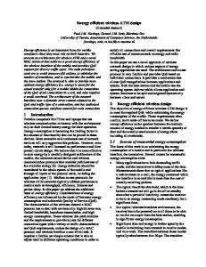
Design of Call Control Signaling in Wireless ATM Networks Nikos H. Loukas, Nikos I. Passas, Lazaros F. Merakos University of Athens, Department of Informatics, Communications Network Laboratory Iakovos S. Venieris National Technical University of Athens, Electrical and Computer Engineering Dept. ABSTRACT: In this paper, a multiservice, local-area, wireless access ATM system is explored from a signaling protocol viewpoint. The signaling architecture considered here follows the signaling structure of Broadband ISDN (B-ISDN) User-Network Interface (UNI), thus offering the possibility for integration of the wireless ATM access system into fixed B-ISDN. It is shown that the use of the employed signaling structure substantially simplifies the call/bearer and handover control. The evaluation of the signaling protocol architecture yields results, which fall within acceptable ATM signaling performance measures. A comparison with alternate access signaling configurations is also carried out to quantify the relative gains. 1. INTRODUCTION The main challenge of wireless ATM is to harmonize the development of broadband wireless mobile systems with fibberoptic-based infrastructure, B-ISDN/ATM and ATM LANs, and offer similar advanced multimedia, multiservice features for the support of time sensitive voice communications, LAN data traffic, video and desktop multimedia applications to the wireless user, [1]. In the described context, a number of efforts are in progress to explore this new technology, [2]-[7]. Most of them comprise wireless research systems that are implementing wireless and mobile ATM, though with different approaches and scope. In this paper, we elaborate on the signaling protocol design of wireless ATM access networks, where the main focus is put on call, bearer and handover control signaling protocols. The proposed signaling protocol structure is based on the same concepts of the fixed broadband access network configurations, currently considered in the standardization fora, [8]. Current trends in designing the access network part of fixed B-ISDN aim at concentrating the traffic of a number of different User Network Interfaces (UNIs) and routing this traffic to the appropriate Service Node (SN) through a broadband V interface (referred as VB), as shown in Figure 1. UNI 1
UNI 2
AN to SN reference point (VB5)
. . .
Service Node (SN)
UNI n
Terminal Equipment (TE)
Access Network (AN)
Figure 1 - Generic Broadband Access Network Configuration
Naturally, the emphasis on access network design is to provide cost efficient implementations without degrading the agreed QoS, and on the other hand to provide high utilization of
network resources. This is reflected in both the reduction of the access network physical equipment and in the limitations imposed on the access network functionality, such as the inability to interpret the full ATM control information and signaling, [9]. The signaling architecture considered here is an extension of the fixed access network control system to the wireless access to ATM scenario and in this respect it can guarantee its integration with fixed B-ISDN. An enhanced version of the existing B-ISDN UNI Call Control signaling, [10], [11], is employed to provide the basic call control function and to handle terminal mobility (e.g., inclusion of mobile-specific messages). In addition, pure ATM signaling access techniques are adopted for the unique identification and control of signaling channels. These features allow us to minimize the changes required to the wired network signaling infrastructure. The proposed signaling protocol structure supports call and bearer control separation through the use of a fast, control protocol, which is employed for the set-up and reconfiguration of bearer connections, and the exchange of appropriate information within the access network. This protocol exploits the design guidelines of the so-called Bearer Channel Control Protocol (BCCP), [9], which is intended to be the standard control protocol for the dynamic VB5.2 interface, [8]. It is shown that the use of this protocol substantially simplifies the call and handover control signaling procedures. Corroborating simulation results are reported to quantify the relative gains. The rest of this paper is organized as follows: in Section 2, the system’s architecture is introduced, and the protocol stacks for the network elements are presented. Section 3 proposes a mechanism to guarantee proper signaling operation and presents the proposed call and bearer control signaling protocol model. Section 4 presents the signaling procedures for the handover control, while Section 5 presents the model used to evaluate the proposed architecture and the extracted numerical results. Finally, Section 6 summarizes our concluding remarks. 2. BASIC ARCHITECTURE AND PROTOCOL STACKS The high-level network architecture assumes a number of geographically distant local-area wireless (and fixed) ATM access systems, interconnected via a core B-ISDN/ATM network, as shown Figure 2. The ATM Mobile Terminals (AMTs) are considered as the equipment of the mobile end-user, and contain the wireless ATM radio adapted cards interfacing the air interface. The Access Points (APs) play the role of base stations and serve the AMTs in their coverage area through a shared radio channel. APs act as gateways for communication between nearby mobile hosts and the backbone ATM/B-ISDN network via the mobile-specific ATM switch. APs do not have switching capability and can be considered as special mobility-aware ATM multiplexers, located at the end of the wired ATM network.
(ASCP). A version of this protocol is currently considered for the VB5.2 interface standard under the term Bearer Channel Connection Protocol (BCCP), [8], [9]. The enhanced UNI Call Control signaling protocol, together with the bearer channel protocol of the VB5 interface, can meet the requirement of call and bearer control separation of the access network considered here. Since a direct call control association between the AMT and the SWS is accomplished, only the fixed (and radio) bearer signaling associations to the old AP have to be released and setup to the new AP using the ASCP, as the AMT moves within the access system.
Figure 2 - High Level View of Network Architecture
The mobile-specific ATM switch is a standard ATM switch equipped with a workstation (Switch-Work Station, SWS). The role of the workstation is to provide the additional functionality for handling the mobility specific functions (e.g. AMT registration, location updating and handover). In addition, it supports the ATM switch in controlling the AMT originated/terminated calls. The corresponding protocol stacks are given in Figure 3. At the user plane (U-plane), the AMT is presented with a typical ATM protocol stack enriched with an additional radio based physical media and a MAC layer (denoted as MAC/PHY). The AP acts as a simple interworking unit that extracts the encapsulated ATM cells from the MAC frame and forwards them to the SWS through a proper ATM virtual connection. The SWS realizes the typical B-ISDN protocol functionality of the Uplane. The control plane (C-plane) protocol model considers the AMT and SWS acting as termination points for Mobile Call Control (MCC) and Mobility Management (MM) Control. Mobile Call Control signaling includes an extended B-ISDN Call Control signaling protocol, [10], (Q.2931*), for the set-up, modification and release of the AMT originated/terminated calls and the support of the handover function. With this architecture, the APs are intentionally kept simple in terms of call and handover control functionality, as only the Bearer and Radio Channel Control (BCC, RCC) protocols are terminated. It is assumed that the registration/authentication and location updating procedures that comprise the basic Mobility Management functions are performed by a location server/database system, which is part of SWS. In the system under study, we follow the approach of decoupling the location management from the connection management system, [14]. This decoupling permits the independent operation of location update schemes. However, the detailed description of these mechanisms is beyond the scope of this paper. With the described network and signaling protocol structure, the AP can be seen as a concentrator of traffic coming from a number of different UNI interfaces and routed to the appropriate service node (i.e., the SWS). The true traffic concentration function realized at AP requires management per VC, which is effected through the use of a bearer channel control protocol between the SWS and the APs, the AP-SWS Control Protocol
Figure 3 - Wireless ATM Access Network Protocol Stack
3. MOBILE CALL CONTROL - BEARER CHANNEL CONTROL A. Signaling Access/Signaling Channels The combination of ATM and wireless networking towards an integrated solution is not a straightforward task. A key problem is the provision of a unique control or signaling channel between the AMT and the SWS, in order to be guaranteed that signaling sessions are uniquely identified in the SWS. This conflict can be solved by dynamically allocating a different signaling VPI/VCI pair for each connection between a particular AMT and the SWS, using the services of the metasignaling protocol, [12]. When a mobile terminal is switched on or enters in the coverage area of an AP’s cell without prior radio connection to another AP, it associates with the AP, i.e. a radio (control) link between the terminal and AP is established. Once this link is setup, the AMT broadcasts an SVC request as a part of the registration message on the uplink metasignaling channel, which is received by the AP and transparently forwarded to the SWS, [13]. Messages that come from different AMTs of the same AP are easily identified, because metasignaling Protocol Data Units (PDUs) are conveyed by single cells. At the registration phase (which forms part of the Mobility Management Control), the AMT reports to the SWS its specific address that uniquely identifies the terminal within the SWS area. When the SWS receives the registration request obtains an available VCI for signaling (SVCI) from its internal database and returns it to the AMT using the downlink broadcast metasignaling channel. SWS notifies the AP about the SVCI value of the particular AMT. In case a mobile terminal is moving from one radio cell to another, it sends a handover request message to the SWS
requesting a handover to another AP using the old radio connection. The SWS upon receipt of a handover request obtains a new SVCI for the AP that the AMT intends to move to, and returns it to the requesting AMT as a parameter of the handover response message. Subsequently, the signaling and data connections are switched to the new AP. In case the old radio link deteriorates so quickly or it is suddenly cut off, the AMT communicates directly with the new AP without any prior notification (forward handover). In this case it is assumed that the handover can only initiated after the mobile has associated itself with the new AP and a new signaling channel between the AMT and the SWS (via the new AP) has been established using metasignaling, [13].
network (B-ISUP IAM message) if the called terminal is a fixed one. In case the called terminal is another AMT (i.e., intra-SWS call), the call processing module of the SWS (having already detected its location) triggers the ASCP entity towards the AP of the called terminal, where similar functions to that described above take place. AP
AMT
SWS
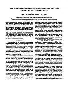
REGISTRATION PHASE SETUP ALLOC ALLOC_COMPLETE CALL_PROCEEDING IAM
B. Call and Bearer Channel Control Signaling When a mobile initiates a new call, its signaling channel transparently conveys a standard call SETUP, [10], signaling message to the SWS (Figure 4). Upon receipt of this request, the MCC in the SWS identifies the calling AMT and the called terminal, and contacts the location server to track the location of the calling AMT and the called terminal (if it is mobile). Moreover, MCC instantiates a state machine for the call, creates a record for mapping connections to the call and performs the necessary routing procedures. An initial call acceptance decision is performed based on the user service profile data and on the QoS requirements set by the AMT, [15], [16]. In case the request is accepted, the Radio Resource Manager (RRM) of the AP, which forms part of the RCC entity, should be notified on the expected new traffic so that it can decide on the admission at the radio part, and allocate radio resources accordingly. To this end, the traffic parameters of the new connection or at least a useful subset of them should be communicated to the AP of the calling AMT. This information gives also the opportunity for exercising a policing functionality at the AP, implemented implicitly by its radio bandwidth allocator. It also protects the SWS from the unlikely case where, although the SWS sees or expects availability of radio resources, these are exhausted due to the additional overheads of the MAC layer, or a temporary reduction in radio link quality. The latter is useful in case the Call Admission Control (CAC) of the SWS does not take into account issues specific to the wireless access. Traffic characteristics will appear at AP together with the QoS requirements, declared as the class of service the specific connection will support. This gives the ability to MAC for implementing a set of priorities according to the connection a cell belongs to. To be able to recognize the particular connection class it is necessary to declare also the VPI/VCI values that will be used. The task of the AP-SWS communication and bearer channel establishment in the fixed access network part is undertaken by the ASCP entity. An ALLOC message is generated and forwarded to the AP (Figure 4). The AP will reply with an ALLOC_COMPLETE or an ALLOC_REJECT message indicating whether it agrees or not with the CAC decision. The latter implies that the call is rejected at the SWS. Upon receipt of an ALLOC_COMPLETE, the SWS returns a CALL_PROCEEDING message to the calling AMT and initiates the call/connection establishment procedures towards the core
RADIO BEARER ESTABLISHMENT
ACM
(CORE B-ISDN)
ANM
CONNECT CONNECT_ACK
Figure 4 - Call Set-up Procedures (outgoing call)
An improvement, in case the requested bandwidth or the QoS cannot be supported by the radio part of the communication path, is for the RRM of the AP to generate an ALLOC_MODIFY message indicating this situation and suggesting a QoS degradation needed for the connection to be accepted. This useful “fallback” mechanism indents to set-up bearer connections with the highest available bandwidth, [14]. However, such a capability in the ASCP protocol is useless if the standard ATM signaling does not support QoS negotiation.The ASCP is also activated in case the UNI protocol supports modification of the characteristics of already established connections i.e., upon reception of a MODIFICATION request message. The calling or called party can initiate the release of the call and its connections. The release procedures in the access network part for the different scenarios are straightforward and are not shown here. Upon receipt of a RELEASE message, the SWS releases all the resources associated with that call and triggers the release of the corresponding connections towards the AP, the core network or the AMT. It should be noted that all ASCP messages could be single cell PDUs marked with a pre-agreed VPI activated in all APs upon installation. The message content is error protected via a 32-bit CRC, specified in the metasignaling protocol description, [12]. A timer is maintained in the ASCP endpoints, which is used to initiate a retransmission procedure in case no reply is received. 4. HANDOVER SIGNALING PROCEDURES As an active AMT moves between wireless cells, the task of forwarding data between the wired ATM network and the AMT must be transferred to the new cell’s AP through a handover process. As the focus of this paper is on the ATM signaling control capabilities required for mobility support, we will not discuss the details of radio aspects of handover. In addition, based on the network architecture presented in Section 2, it is assumed that AMTs can move within the radio access environment within the SWS area. We do not refer to inter-SWS handovers in this paper.
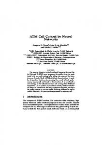
In the system considered here, it is assumed that only the mobile terminal monitors the quality of the radio link for the current and the candidate APs, and decides whether to initiate a handover or not. It is assumed that the handover is predicted ahead of time and the handover execution is initiated via the old AP (backward handover). The forward handover scenario appears similar and it will not be presented. As the AMT decides that a handover should be performed sends a HANDOVER_REQUEST message (Figure 5) towards the Mobile Call Control entity of the SWS transparently via the old AP. This message contains an identification of the AMT, the call and the target AP. Possibly, an AMT may have multiple active connections at the same time, as multimedia applications are to be supported. To this end, during a request for handover the AMT could also indicate the priorities of the different connections in case the new AP cannot accommodate all the AMT connections. The fast control protocol between AP-SWS (ASCP) described in Section 3, is also employed here for the release/establishment of the old/new bearers in the fixed network part and for performing possible QoS renegotiations during handover. Upon receipt of the HANDOVER_REQUEST, the SWS identifies the AMT, initiates a state machine for the handover, obtains the new VPI/VCI (and SVCI) values and activates the ASCP entity towards the new AP. The SWS informs the RRM of the target AP about the expected QoS and bandwidth requirements to allocate radio resources accordingly. Since the SWS maintains the overall resource and connection information, it allocates new VPI/VCI values for the new connections and forewords them to the new AP. AMT
APold
APnew
SWS
notify it that the connection no longer exists and to deallocate the corresponding radio resources. The handover process, as described above, is expected to be quick. Thus, it is not likely that an AMT may move again before the handover is accomplished. But if the AMT moves, handover is again attempted to the current destination AP, and will eventually succeed. In the analysis presented above, it was implicitly assumed that no QoS degradation is observed in the new path (including both radio and fixed connections) after the handover execution. Complications arise if this new path is not able to support the same QoS, or if cannot accommodate new connections - this situation is mainly considered for the radio part of the path, where bandwidth is a scarce resource. In this case, the network should be able to start a QoS renegotiation procedure towards the AMT that experiences a handover. It has to be noted that given the time constraints imposed by the moving AMTs, QoS re-negotiation may not be feasible, [17]. This way, the handover of one or more connections can fail due to lack of radio resources, but the connections for which there are sufficient resources can still be handed over. The AP-SWS Control Protocol, as defined in Section 3, fully supports these requirements. In case the requested bandwidth or the QoS cannot be supported by the radio part of the new AP, its RRM generates an ALLOC_MODIFY message indicating this situation and suggesting a QoS degradation needed for the connection to be accepted. Taking into account the real-time features of the ASCP and the fact that the RRM immediately generates a request for QoS modification, there is no extra delay on handover to cope with such situations. Obviously, if no satisfactory QoS can be obtained at the new AP, then the handover is rejected.
ACTIVE CALL HANDOVER_REQUEST
ALLOC
HANDOVER_RESPONSE
ALLOC_COMPLETE
OLD RADIO BEARER RELEASE - ESTABLISHMENT OF NEW RADIO BEARERS TRAFFIC REROUTING RELEASE
Figure 5 - Handover Signaling Procedures
When the SWS receives the response from the new AP (ALLOC_COMPLETE), sends a HANDOVER_RESPONSE message to the AMT to inform it about the handover results, the new VPI/VCI (and SVCI) values and possible QoS modifications and reconfigures the ATM connections towards the new AP. The HANDOVER_RESPONSE message indicates to the AMT that it can proceed to perform handover. AMT releases its radio connection with the old AP and establishes a radio link with the new AP, retrieving in this way its connectivity with the fixed network. Special ATM (and lower) layer cell relay functions take place at AMT and SWS to co-ordinate the switching of traffic and to guarantee the transport of user data at an agreed QoS level in terms of cell loss, ordering and delay. Finally, the location server is updated about the new location of the AMT and a RELEASE message is sent to the old AP, to
5. PERFORMANCE MODEL - NUMERICAL RESULTS A. Performance Model Description In this section, the architectural signaling protocol design carried out in this paper is quantitatively studied by simulation. The objective is to obtain measures for the mean signaling processing delay at call set-up and handover, and to study the behavior and the capacity of the access system under light and heavy signaling loads, in order to reveal the maximum number of AMTs the system can accommodate in each case. A comparative performance analysis between an alternate signaling access architecture is also carried out to quantify the relative gains. We consider an access network configuration that consists of 20 APs attached in one SWS (similar to that shown in Figure 2). It is assumed that the moving AMTs are uniformly spread within the access system (so that the number of users within each AP area is the same), no handovers occur during call or bearer setup, generation of call set-up/release or handover requests is considered as Poisson, and the moving AMTs do not move again before the handover is accomplished, [16]. Figure 6 illustrates the processing model considered for the evaluation of the signaling performance. In this figure, each block represents a functional group (or a subsystem in the terminology of [18]), that is, the model describes the procedures activated in SWS and AP during signaling operation. This model considers only the “Layer 3” signaling messages processing.
Processing delays introduced by the lower layers are not taken into account. Following the methodology introduced in [18], [19], we assume that all functional blocks are executed by separate controllers. The service times for each block and for the different message types are shown in Table I, [9], [15], [16], [18], [19]. All queues are assumed to have infinite capacity. Interblock system delays are taken equal to 5 ms in analogy to [15], [19]. On each signaling link between access network nodes, we ignore propagation delays, emission times and link queuing delays. The simulation tool used for this performance evaluation is the OPNET 2.5A, [20].
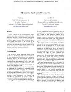
minutes, [16]. Moreover, we assume that the 50% of users is moving, even they are idle (not in a call) or active (involved in a call). Idle AMTs simply register their location as they move. The mean rate of handover or location updating requests for each moving AMT is 1 handover request/min (for an active AMT) or 1 location updating request/min (for an idle AMT), respectively. B. Numerical Results Figure 7 illustrates the mean processing times at call set-up (Tcp, Tsetup) and handover (Tresp) at various call arrival rates per AMT. The curves represent 10 runs of each scenario. As expected, as the number of AMTs per AP increases there is a straightforward increase at call set-up and handover processing times. It has to be noticed that the presence of lower layers in a real wireless ATM access system will further increase the processing times. From the results, shown in this figure, we can obtain the maximum number of terminals that an AP (and consequently the system) can accommodate depending on the user mobility and the total load of newly arriving calls. 10 calls/hr/AMT Mean Processing Time (ms) 550 500
Tcp Tsetup
450
Tresp
Fig. 6 - Signaling Processing Performance Model
400
15 calls/hr/AMT
350
Parameter Mobile Call Control
ASCP Resource Handler Location Server/ Data Base SAAL processing time at AP (for ‘Full Q.2931’ scenario)
Processing time 30 ms ( call set-up operation) 20 ms (handover operation) 10 ms (call release operation) 5 ms (for all operations) 5 ms 15 ms (invocation processing time) 5 ms (update processing time) 1 ms
Table I. Processing Times of the Performance Model
Our performance analysis focused on three parameters. First, the mean time from the start of a call SETUP message to the receipt of the CALL_PROCEEDING message at the calling AMT (for outgoing and local calls) or the SWS (for incoming calls) is measured, denoted as Tcp. The CALL_PROCEEDING message acknowledges the SETUP message and indicates that the call is being processed and (according to the currently available standards) no more call establishment information will be accepted. The second performance measure is the mean endto-end delay (denoted as Tsetup) to establish local calls, between two AMTs attached to the same SWS. The third performance parameter is the time from the start of HANDOVER_REQUEST until the receipt of HANDOVER_RESPONSE at the AMT (denoted as Tresp), which the critical time interval for the MCC at the SWS to decide on the handover acceptance and to establish the new bearers in the fixed radio part. In the system under study we assume that a 20% percentage of the total call set-up requests that arrive to the SWS comprise outgoing calls, a 20% refers to incoming calls, while the remaining 60% represents local calls. The duration of each call is exponentially distributed with mean duration time equal to 3
300 250 200 150 100 50 0
25
50
75
100
125
150
Number of Terminals per AP 5 calls/hr/AMT
Fig. 7 - Mean Processing at Call Setup and Handover
The second part of simulation results compares the proposed signaling architecture with an alternate signaling protocol structure, considered in many wireless systems that are implementing wireless and mobile ATM, [5], [14]. This configuration assumes that both the APs and SWS realize the full UNI signaling protocol stack, and in this way the call/connection set-up and the handover signaling procedures are performed sequentially from the AMT to AP, from AP to SWS etc., using standard set-up or handover requests, [5], [14]. We refer to this structure as the “Full Q.2931” approach. The objective of this performance comparison is to examine the signaling performance differences of the two architectures in terms of the performance measures considered above (Tcp, Tsetup, Tresp). The mean call arrival rate is 10 calls/hr/AMT. The processing parameters shown in Table I have been used. Figure 8 demonstrates the obtained results, for the call set-up and handover processing delays, respectively, proving the efficiency of the proposed signaling architecture. The extracted results imply that the processors of the proposed approach, denoted as “ASCP” approach, saturate at higher call and handover arrival rates than the processors in the “Full Q.2931” approach. The performance difference between the two architectures is due to
the call/bearer control separation adopted in our approach, which decouples the call control from bearer channel control operations resulting in reduced connection control processing. Full Q.2931 Mean Processing Time (ms) 550 500
Tcp Tsetup
450
Tresp
400 350 300
Full Q.2931
250
ASCP
200 150 100
ASCP
50 0
25
50
75
100
125
150
Number of Terminals per AP (10 calls/hr/AMT)
Fig. 8 - Comparison of “ASCP”-”Full Q.2931”
Beyond the signaling processing efficiency, the effectiveness of our approach can be demonstrated if a comparison is made in terms of complexity and cost. The proposed structure considers that the APs are kept transparent to call control and simple in terms of layering. The complexity of the AP translates directly into the overall infrastructure cost since numerous APs are necessary to span a network, especially if a pico-cell size is assumed. Moreover, the power consumption at the AP can be considered proportional to the complexity. Implementing the full signaling protocol stack in each AP adds the most complexity onto the AP, which results in high costs, high power consumption and low reliability. 6. CONCLUSIONS In this paper, a broadband, wireless ATM access system for local-area networks was explored from a signaling protocol viewpoint. A basic architecture including signaling interfaces and protocol stacks has been proposed, which provides signaling integration of a mobile ATM access system into B-ISDN. A pure ATM wireless access signaling technique has been introduced, based on the ATM metasignaling approach. A simple and flexible bearer control protocol was employed, which allows call-bearer separation and efficient handling of user mobility. The architectural signaling protocol design carried out in this paper was quantitatively studied by simulation. The obtained results capture the effect of the architectural and protocol design on the performance of call and mobility control in terms of call set-up and handover mean processing delay. A comparison of our approach with alternate access signaling configurations quantifies the relative gains in terms of signaling processing efficiency, complexity and cost. REFERENCES [1] D. Raychaudhuri, N. D. Wilson, “ATM-Based Transport Architecture for Multiservices Wireless Personal Communication Networks”, IEEE JSAC, vol.12, no.8, pp.14011414 , Oct. 1994.
[2]P. Agrawal et al., “SWAN: A mobile multimedia wireless network”, IEEE Pers. Comm, Vol. 3, No. 2, pp.18-33, April 1996. [3] Condon et al., “A wireless ATM Local Area Network using infrared links”, in Proc. ACM Mobicom ’95, pp. 151-160, Berkeley, Nov. 1995. [4] K.Y.Eng et al, “A wireless broadband ad-hoc ATM local area network”, ACM Wireless Networks, Vol. 1, No. 2, pp. 161-174, July 1995. [5] D. Raychaudhuri et al., “WATMnet: A prototype wireless ATM system for multimedia personal communication”, Proc. IEEE ICC ’96, pp. 469-477, Dallas, June 1996. [8] J. Porter and A. Hopper, “An overview of the ORL wireless ATM system”, IEEE ATM Workshop, Washington, DC, Sept. 1995. [7] I. Leslie and D. McAuley, “Fairisle: An ATM network for the local area”, ACM Computer Communication Review, Vol. 21, No.4, Sept. 1991. [8] ETSI, “Signaling Protocols and Switching - V interfaces at the digital Service Node (SN)”, V1.5, DTR/SPS -03040, Oct. 1995. [9] I.S.Venieris et al., “Architectural and control aspects of the multi-host ATM subscriber loop”, Journal of Network and Systems Management, Vol.5, No.1, pp.55-71, Febr.-April 1997. [10] ITU-T Recommendation Q.2931, “B-ISDN User Network Interface Layer 3 Specification for Basic Call / Bearer Control”, Dec. 1993. [11] ATM Forum, “UNI Specification”, Version 4, 1995. [12] ITU-T Recommendation Q.2120, “B-ISDN Metasignaling Protocol”, May 1993. [13] N. Passas, N. Loukas, A. Kaloxylos, T. Kuehnel, Y.S.Wu, “Alternatives of signaling channel allocation in wireless ATM networks”, Proc. of International Workshop on Mobile Communications ’96, pp. 149-153, Thessaloniki, September 96. [14] R. Yuan, S.K. Biswas, and D. Raychaudhuri, “A signaling and control architecture for mobility support in wireless ATM networks”, Proc. IEEE ICC ’96, pp. 478-484, Dallas, June 1996. [15] M. Veeraraghavan, T.F.LaPorta and W.S.Lai, “An alternative approach to call/connection control in broadband switching systems”, IEEE Comm. Mag., Vol. 33, No. 11, pp. 9096, Dec. 1995. [16] M. Veeraraghavan, T.F.LaPorta and R. Ramjee, “A distributed strategy for wireless ATM networks”, ACM Wireless Journal, Vol. 1, No. 3, pp. 323-339, Oct. 1995. [17] C.K.Toh, “The design and implementation of a hybrid handover protocol for multi-media wireless LANs”, in Proc. ACM Mobicom ’95, pp. 49-61, Berkeley, Nov. 1995. [18] M. Bafutto, P.J. Kuehn, G. Willmann, “Capacity and Performance Analysis of Signaling Networks in Multivendor Environments”, IEEE J. Select. Areas Commun., Vol. 12, No. 3, April 1994. [19] G. Willmann and P.J. Kuehn, “Performance modeling of SS7”, IEEE Comm. Mag., Vol. 28, No. 7,pp. 44-56, July 1990. [20]OPNET Modeler, Tutorial Manual, MIL 3, Inc., 3400 International Drive NW, Washington, DC 20008, 1993.