International Journal of Engineering, Science and Technology Vol. 3, No. 5, 2011, pp. 73-82
MultiCraft
INTERNATIONAL JOURNAL OF ENGINEERING, SCIENCE AND TECHNOLOGY www.ijest-ng.com © 2011 MultiCraft Limited. All rights reserved
Laboratory development of wind turbine simulator using variable speed induction motor S. W. Mohod1*, M. V. Aware2 1*
Department of Electronics Engineering, Prof.Ram Meghe Institute of Technology& Research, Badnera-Amravati, INDIA 2 Department of Electrical Engineering, Visvesvaraya National Institute of Technology Nagpur, INDIA * Corresponding Author: e-mail:
[email protected],
[email protected], Tel +91-0721-2579901,
Abstract The conventional synchronous generators in wind energy conversion system are now getting replaced by variable speed induction generator to extract maximum power with wide range of wind speed limit. The design and performance of such systems requires a simplified digital simulator, especially for the development of a optimal control solution .The proposed work is to make a prototype of variable speed wind conversion system simulator for a required operational condition under variable wind speed. In this paper variable speed induction motor drive using scalar control is interfaced in wind energy conversion system as an alternative to make the real time wind simulator for wind energy researchers. The basic power curve from wind generator is carried out through d-SPACE and interface of induction motor through an inverter control system. The induction motor is operated in wide speed range using Volt /Hertz speed control scheme. The laboratory prototype consists of 3 kW, 415 Volt, 50Hz induction motor controlled by voltage source inverter for various wind speed. The paper demonstrates the steady state characteristics of wind turbine without dependence on natural wind speed using Volt/Hertz. The basic control strategy is implemented through hardware system. The result verifies that the wind turbine simulator can reproduce the steady state characteristics of a given wind turbine at various wind conditions. . Keywords: Inverter technology, Volt-per-Hertz control, Wind turbine simulator , Wind conversion system. 1. Introduction In renewable energy source wind power has become most attractive. In order to improve the energy conversion efficiency of wind generation system, recently variable speed generations are getting used. The Variable speed operation yields 20 to 30 % more energy than fixed speed operation. The wind turbine is regulated to capture the maximum wind power. The task of wind turbine control system is to keep the rotor shaft speed and active power at set level. The system typically consists of speed regulator, power regulator & blade pitch regulator. The wind turbines are dependent upon airflows which are subjected to weather conditions & local effects. This results in the variation of primary energy over which the turbine has no influence. Thus due to the uncontrollable natural characteristics of wind speed and the large size of wind turbine, it is very difficult to perform the experimental study in laboratory (Yaoqin Jia,et al ,2007). As a result, a great deal of research has been focused on the development of wind turbine design in order to reduce the cost of wind power and to make wind turbine more economical and efficient. Wind energy conversion system involves high performance wind turbine simulator for the development of control system. To enhance the power quality of wind energy conversion system the wind turbine simulator is used as a necessary tool in research laboratories. The wind energy conversion system simulates the steady state wind turbine behaviors in a controlled environment without dependence on natural wind resource and actual wind turbines (Hossein Madadi et al 2004). In past few years, there has been much research going on to develop the wind turbine simulator which mainly focuses on aerodynamic model of wind turbine rotor (Seman slavomir et al ,2006 and Mansuri M.N et al ,2004). Different types of machines have been used to emulate the turbine shaft; both the induction and DC motor have been used in wind turbine simulators (A.A.C.Nunes et al, 1993). The common wind simulator is based on the DC motor with current control as a prime-mover. The armature and field circuit was controlled so that the dc machine generates static characteristics of a constant pitch wind turbine. However this simulator is unattractive due to the
74
Mohod and,Aware / International Journal of Engineering, Science and Technology, Vol. 3, No. 5, 2011, pp. 73-82
use of large size of DC motor, frequent maintenance and more expensive (Weiwel Li, et al, 2007). The real wind system simulator with control strategies having output torque using induction motor was presented to give torque-speed curve of actual wind turbine (C.Nichita et al, 1998). The wind turbine model and controller were developed on a ‘C’-language platform (Hossein Madadi et al, 2004).The emulator of wind turbine generator using dual inverter controlled squirrel-cage induction motor, which consist of two inverters, one as a prime mover and other as a variable speed generator was presented based on DSP processing (Varin Vongmanee et al ,2009). The virtual model for prediction of wind turbine parameters was presented (Andrew Kusiak et al,2010 and Bunlung Neammanee et al ,2004).The wide range of wind speed with variable induction generator to enhance the power industry is expected to dominate the wind energy conversion systems. This area requires more investigation; hence the laboratory simulators are required. In this paper, a three phase inverter with volt/hertz control approach of induction motor is used as a wind turbine simulator. The induction motor drive is controlled using the measured shaft torque from speed estimator. The proposed wind turbine simulator is achieved by close loop control of rotor speed ( ω r ) and torque control. A maximum power point tracking method including feed forward and feed-back system is represented to improve the efficiency of wind power conversion (A.B.Raju et al,2004). The power-speed pattern of wind can be generated from the data base or from actual recorded wind speed data or from manual set-up. The proposed simulator determines the wind turbine characteristics at various wind speed and loads characteristic for various rotor speed. The paper is organized as follows: The structure of variable speed wind generator system is organized in section II and wind turbine simulator of laboratory in section III. The model of wind turbine is presented in section IV and model of induction motor in section V. The section VI describes the design of controller. Section VII shows the implementation of experimental system with the conclusion in section VIII. 2. Wind Energy Conversion System Structure The wind energy conversion structure is analogues to the based on the field system. Typical wind energy generating systems are classified as fixed and variable speed. 2.1 Conventional fixed speed wind energy system: In conventional fixed speed type the wind turbine is directly or with gear is connected to grid as shown in Figure 1.
υ
supervisory control system Power & Speed control
ω Generator
Transformer
Grid
Figure 1. Fixed speed type wind energy conversion system. The wind energy generating system has a supervisory control system located at the main level and turbine control system for power & speed control. The functions of supervisory control system are as – • To generate reference signals sequentially for the power & speed control system for the wind turbine generator system to pass from one operating state to another. • To perform the protective function. The turbine control system acts on turbine and its purpose to-regulate the torque, smoothen the wind turbine output power and to damp the electromechanical oscillation. • To protect the costly mechanical equipments.
75
Mohod and,Aware / International Journal of Engineering, Science and Technology, Vol. 3, No. 5, 2011, pp. 73-82
Generally both the control systems are utilized in such a fixed type wind energy conversion system. 2.2 Variable speed wind generating system: A variable speed wind generating system connected to the grid is shown in Figure 2.
υ
supervisory control system Power & Speed control
DC LINK
ω Generator
Rectifier
Inverter Grid
Monitoring and control
Figure 2. Variable speed type wind energy conversion In variable speed type grid connected wind energy conversion system has rectifier on generator side which converts the generator voltage or current to a dc link. Thus controls the generator operation and the wind turbine. The dc link decouples the grid frequency and generator frequency. The performance of dc link is influenced by the voltage and current level within it. The grid is supplied via the inverter. Thus the system has speed regulator, power regulator, pitch angle regulator and inverter controller as the main controller during power system operations. 3. System Modeling 3.1 Wind turbine model: Wind energy is the kinetic energy that is of large masses of air moving over the earth’s surface. The blades of the wind turbine receive the kinetic energy, which is then transformed to the mechanical or electrical forms depending on end usage. The efficiency of converting wind energy to useful energy form depends on the efficiency with which rotor interacts with the wind streams (Mihel-Popa et al,2004). The kinetic energy of a stream of air with mass m and moving with velocity V is given in (1).
E=
1 mV 2 2
(1)
The kinetic energy of an air stream available for wind turbine having cross section area A and mass m that is equal to ρν moving velocity Vw is given in (2).
E=
and
1 ρνVw 2 2
(2)
1 ρAVw3 2
(3)
Where the ρ is the density of air and v is a volume of air portion available to the rotor. The power from the wind is the kinetic energy on which the air is interacting with rotor per unit time has a cross section area A, can be expressed as (3).
Pw = 3
Typically, the density of air is taken as 1.225 kg / m . It is seen that effect of wind velocity is prominent to cubic relationship to power. However, wind power cannot be fully converted to mechanical power, so the power at the shaft is given in (4).
Pm = C p ( Pw ) Pm =
1 C p ρAVw3 2
Where `Cp is the wind power coefficient that depends on the ratio between the turbine speed ω r R and the wind speed
This ratio is called tip speed ratio λ and is given as (5).
(4)
Vw in m/sec.
76
Mohod and,Aware / International Journal of Engineering, Science and Technology, Vol. 3, No. 5, 2011, pp. 73-82
λ=
ωr R
(5)
Vw
ωr is the turbine angular speed. The maximum Cp is 0.59, thus the maximum power that can be realized from wind system is 59% of the total wind power .The value of Cp is also a function of a pitch angle β . The change in β will affect the lift and drag forces acting on blade, thus modifying the output power. In this paper fixed pitch Here R is the radius of turbine in meter and
angle is considered as it is for small and medium sized turbines.
Pm =
1 C p (λ , β ) ρAVw3 . 2
(6)
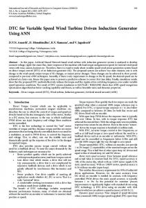
Therefore Cp depends on λ . In practice wind turbine is characterized by non dimensional curve of coefficient of performance CP as a function of tip speed ratio λ and shown in Figure 4 and Figure 5 respectively. Wind turbine characteristics 12 m/s 1.2
1
11 m/s
Power (pu)
0.8 10 m/s 0.6 9 m/s 0.4 8 m/s 0.2
7 m/s
6 m/s 5 m/s
0 500
1000 1500 Turbine speed referred to generator side (rpm)
2000
Figure 4. Practical wind turbine characteristic
Cp
4
λ
12
8
Figure 5. CP -
λ
curve
The mechanical power is transmitted to the generator through mechanical transmission efficiency η m and which is converted to electricity with efficiencyη g . The electrical power output Pe is given in (7).
Pe = ηmη g Pm 3.2 Induction motor model:
(7)
77
Mohod and,Aware / International Journal of Engineering, Science and Technology, Vol. 3, No. 5, 2011, pp. 73-82
The model of an induction motor is highly nonlinear and mutually coupled. The dynamic model of induction machine must be known in order to study and design the control of induction machine. The complete model is dictating as a simple per phase model of induction motor as shown in Figure 6.
RS
Is Vs
Lr
LS
Ir Rr/s
Lm
Figure 6. Induction motor model It is used to develop an appropriate controller with the input output model which relates stator voltage Vs, angular speed developed torque Tm. The following are the assumptions made • The dynamics of the subsystems are neglected as its time constant is smaller than the mechanical subsystem. • Saturation and parameters are neglected. • Core losses of the machines are neglected. • The impedance of magnetizing circuit is considered larger than the stator impedance.
ωr
and
The stator terminal voltage Vs is approximately considered as air-gap flux generated emf Vm. The rotor induced voltage Vr/
causes rotor current I r/ at a slip frequency ω sl , which is limited by rotor resistance and reactance. The phase diagram represents Lm, Rs are the magnetizing inductance and stator resistance and Ls, Lr are the stator and rotor inductance referred to input. The induction model consists of an algebraic equation which governs the flux linkage
ϕ = Vs ω
, where e
ωe is the supply frequency.
The magnitude of current Ir can be written as in (8).
Ir =
Vs ( Rs + Rr S ) 2 + ωe2 ( Ls + Lr ) 2
(8)
The torque expression is written in (9).
Te = 3(P 2 )I r2 The dynamics equation that relates the rotor angular speed (10),(11).
T e= TL + J
Rr Sωe
(9)
ωr , motor electromagnetic torque Tm and load torque TL is given in
dω r dt
(10)
Where J is the rotor inertia. 2 ⎛P⎞ ϕ ω R Tm = 3⎜ ⎟ 2 sl 2 r 2 ⎝ 2 ⎠ Rr + Lrω sl
(11)
The equation shows the relationship between rotor current and slip frequency at a given flux which is constant in constant torque operating region. 4. Implementation of Wind Simulator The simplified structure of wind simulator in the laboratory is realized by replacing the turbine rotor, gearbox, supervisory control system with volt/Hertz control of induction motor. The three-phase IGBT inverter and induction motor behaves like a real wind turbine in steady state as shown in Figure 3.
78
Mohod and,Aware / International Journal of Engineering, Science and Technology, Vol. 3, No. 5, 2011, pp. 73-82
I.M.
3-ph supply
DC Excitation
Alt.
Wind simulator (volt /Hz) control
Load
Figure 3. Simplified wind simulator in laboratory. The simulator comprises of an induction motor that is controlled to simulate the torque-speed characteristics of actual wind turbine. The manufacturer emphasizes to control the output torque of motor according to wind profile situation and rotating speed of wind turbine. Thus wind turbine simulator is to initiate the external characteristics of real turbine. At a given wind speed, the operating point of wind turbine is determined by the intersection between turbine characteristics and load characteristics. The monitoring and control is developed to facilitate the experimental study in the laboratory. 4.1 Controller and its designIn a wind turbine simulator the power speed characteristics of wind turbine are physically implemented by close loop of Volt/Hertz control of induction motor as shown in Figure 7. The shaft power Pm & speed ω r of induction motor represents the power & speed of wind turbine rotor.
V/HZ
Vs∗
ωr∗
ωr
Pw
Pw
ωr
PI
ωsl∗
controller
ωsl∗
To PWM Inverter
ωr
ωsl∗
Va,Vb,Vc Speed Estimator ia,ib,ic
Figure 7. Volt/Hertz controller for induction motor The constant Volt/Hertz principle is used to provide controlled slip operation in order to reproduce the turbine characteristics. The wind speed signal for the simulator is supplied from wind profile which can be obtained from the measured wind data from site. The simulator has an outer loop speed control and a PI regulator that generates slip which is added to the shaft speed to generate the stator frequency command. The frequency command ωe also generates the voltage command through Volt/Hertz generator. If this ratio is kept constant, the stator flux will remain constant & so the motor torque will only depend on slip frequency and permits the fast response of the drive. The machine terminal voltage can also be programmed through lookup table. The inverter fed induction motor receives both the input ωe & Vs, which commands a three phase sinusoidal generator by pulse – width modulation in the inverter. Thus the system of wind simulator can be used for researchers for their studies on wind turbine drive trains in a controllable test environment in the laboratory. A shaft mounted speed encoder is used for a closed system in scalar control. It is possible to estimate the speed signal from machine terminal voltage and current with the help of DSPACE/DSP. The digital controller synthesizes the control input
79
Mohod and,Aware / International Journal of Engineering, Science and Technology, Vol. 3, No. 5, 2011, pp. 73-82
from feedback signal of
ωr and
Tm and set point Pm. The stator voltage and current are needed to represent in
d s − q s and
d r − q r circuit. The stator equation is shown in (12).
d s ϕ qs dt d Vdss = Rs idss + ϕ dss dt Vqss = Rs iqss +
The
ϕ qss , ϕ dss
(12) (13)
are q-axis and d-axis flux linkage. The rotor equation in rotating form is shown in (14) and (15).
d ϕ qs + ωeϕ ds dt d Vds = Rs ids + ϕ ds + ωeϕ qs dt Vqs = Rs iqs +
(14) (15)
The flux linkages in terms of current can be expressed as in (16).
ϕ qs = Ls iqs + Lm (iqs + iqr )
(16)
The development of torque by the interaction of air gap flux and rotor mmf gives the following equation in (17) and (18).
(
3 (P 2) ϕ dms iqss − ϕ qms idrs 2 3 Te = (P 2) ϕ dss iqss − ϕ qss idss 2 Te =
(
Where
)
)
(17) (18)
ϕ dm - is the mutual flux linkages.
In this scalar control, speed signal ω r is directly available as a control variable. Thus the speed estimation gives torque speed control signal for the operation of Volt/Hertz control. 5. System parameters The experimental parameters for the laboratory setup are given in the Table. I TABLE I System Parameters S. N. 1
Parameters Induction Motor
2
Alternator
3
IGBT Rating
4
Load Parameter
Ratings 3-phase,3HP/2.2 kW,415V, 50 Hz,P = 4,Speed = 1440 rpm, Rs = 0.01Ω, Rr = 0.015 Ω ,Ls =0.06H, Lr=0.06H , J=0.8kg/m2 3-KVA,415 Volt ,1500rpm,50 Hz, Excitation-220 Volt,1.4 Amp Collector Voltage = 1200V , Forward Current =50A, Gate voltage = 20V, Power dissipation = 310W Load -3kW.
6. Experimental Wind Simulator The experimental wind simulator consists of: 6.1 Laboratory simulator system: The laboratory wind turbine simulator model is developed as shown in Figure 8 and the results are plotted. The hardware consists of-
80
Mohod and,Aware / International Journal of Engineering, Science and Technology, Vol. 3, No. 5, 2011, pp. 73-82 • • • •
Three phase squirrel cage induction motor 2.2kW/3HP, 1400 rpm. 50 Hz. Pulse rotary encoder Volt/Hertz control of inverter Controller 16 bit,d-SPACE-TMS320LF2407
The d-space processor provides the computing power for the real time system and also functions as interface to input-output board and PC. The d-space choice is for the application with high sampling rate and fast access to I/O hardware. The d-space can be programmed from simulink via real time interface.
Induction Motor Generator
PWM
Load
Volt /Hz control
3-ph supply
speed Estimator
d-SPACE DECstation
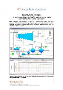
Figure 8. Hardware structure of wind turbine simulator The speed signal from encoder is send to the Volt/Hertz control of inverter via a data acquisition interface circuit inside the circuit board. Wind data simulation software program can be developed and implemented by using d-SPACE board. The algorithm can receive the rotational speed signals from the encoder and torque on the motor can be controlled using volt/Hz control. The experimental simulator is used for the determination of wind turbine characteristics for different wind speeds and figures were obtained keeping the field current and field voltage of generator constant in the experimental setup and is shown in Figure 9. The result verifies that the simulator can reproduce the steady-state characteristics of a given wind turbine as shown in wind turbine model. 600 High wind speed
500 Power (W) 400
300
200 Low wind speed
100
0
0
200
400
600 800 1000 Rotor speed (rpm)
1200
1400
Figure 9. Characteristics of a turbine simulator
1600
81
Mohod and,Aware / International Journal of Engineering, Science and Technology, Vol. 3, No. 5, 2011, pp. 73-82 It is seen that the output voltage of a generator is proportional to its rotating speed and the maximum output power is also proportional to output generated voltage for various rotor speed which is plotted in Figure 10. 450 400 Voltage Vg (V) 350
50Hz (1440rpm) 40Hz (1170rpm)
300 250
30 Hz
(875rpm)
200 150 1060
20 Hz (580rpm)
560 0 0
0.5
1
1.5
2
2.5
3
Load Current (A)
Figure 10. Generated voltage for various rotor speed The controller generates the set value of current and frequency for the IGBT inverter. The inverter control system is implemented using associated hardware and software in d-SPACE. The inverter output line voltage and line current waveform at low speed of 875 rpm are presented in Figure11.
Figure 11. Inverter output voltage and current, (upper track- line current, Lower track- Line Voltage)
7. Conclusion The experimental wind turbine simulator for wind generating systems is presented for the determination of characteristics of real turbine for various wind speeds. The practical simulator can use the algorithm of available site wind data for the researchers in laboratory to enhance the quality of wind turbine conversion system. The advantages of the simulator can be incorporated as desired in control strategy and in supervisory data control system. In comparison the DFIG control is tied to the rotor only and the slip power is processed. The DFIG is not as rugged as that of squirrel-cage type, the brush has wear and sparking when compared with induction generator. In DFIG only part of power production is fed through power converter. Now a day’s converter technology is matured for high power production. The developed simulator is simple, low cost and designed for volt/Hz control and operates on high performance d-SPACE board. The experimental results are plotted for the power characteristics of wind turbine and are matched with steady state wind turbine characteristics. References A.A.C.Nunes, P.F.Seisas, P.C.cortizo, S.R.silva, “Wind turbine simulator using DC machine and a reversible converter”, Proc. International Conference on Electrical Machine, vol. 3,pp.536-540,Adelide,1993. Andrew Kusiak,Wenyan Li, “Virtual model for prediction of wind turbine parameters” IEEE Trans. on Energy Conversion, vol. 25, no.1,pp.245-254,March 2010. A.B.Raju,B.G.Farnandes,K.Chatterjee “A UPF power conditioner with maximum power point tracker for grid connected variable speed wind energy conversion system”, IEEE conference Power Electronic system and application, Hong-Kong pp. 107112,2004. Bunlung Neammanee, Somporn Sirisumrannukul, “Development of wind turbine simulator for wind generator testing”, International Energy Journal, vol.8,pp.21-28 ,2007
82
Mohod and,Aware / International Journal of Engineering, Science and Technology, Vol. 3, No. 5, 2011, pp. 73-82
C.Nichita,A.D.Diop,J.Ethache,B.Dakyo,“Control structure analysis for a real wind system simulator”, Wind Engineering,vol.22, no.6,pp.275-286,1998. Hossein Madadi, Kojabadi,Liuchang , “Development of a novel wind turbine simulator for wind energy conversion systems using an inverter controlled induction motor”, Transaction on Energy conversion, vol. 19, no. 3,pp. 547-555,Sept.2004. Mihel-Popa Lucian, Blaabjerg Fred, Boldea Ion, “Wind turbine generator modeling and simulation where rotational speed is controllable variable ,” IEEE Trans. on Industry Application ,vol 4: pp.3-10, 2004. Mansuri M.N.,Mimouni M.F.,Benghanem B.,Simulation model for wind turbine with asynchronous generator interconnected to the electric network”, Renewable Energy,Vol.29, PP.421-423. 2004. Seman slavomir,Iov F.,Niiranen J, Arkkio A, “Comparison of simulator for variable speed wind turbine”, International journal of Energy Research, Vol. 30.pp.713.-728, 2006. Varin Vongmanee, Emulator of wind turbine generator using dual inverter controlled squirrel cage induction motor, Proc. of IEEE International conference on power Electronics& Drives, pp.1313-1322, 2009. Weiwel Li,Dianguo Xu, Wei Zhang,Hongfei Ma, “Research on wind turbine emulation based on DC motor” IEEE International conference on Industrial Electronic Application,pp.2589-2593.2007. Yaoqin Jia, Zhaon Wang, “Experimental study of control strategy for wind generation system “ proceeding of IEEE, pp. 12021208,2007. Biographical notes Sharad W. Mohod - received B.E. degree in Electrical Engineering and M.E. degree from Govt.College of Engineering Aurangabad, India in 1988 and 1991.He was an Electrical Engineer in M/S Garware Polyester Ltd Aurangabad from 1988-1991. In 1991, he join College of Engineering Badnera - Amravati, and presently working as Associate Professor in Dept. of Electronic Engineering, Prof. Ram Meghe Institute of Technology & Research Badnera-Amravati, India. Presently, he is pursuing for Ph.D.degree in Visvesvaraya National Institute of Technology, Nagpur, India. Currently he is a member of IEEE(USA), IE (I), IETE, LMISTE .He has many publications in IEEE journal and conferences. Dr. Mohan V. Aware - received the B.E.degree in Electrical Engg. from the Govt. College of Engineering, Amravati, India, in 1980.and M.Tech degree from Indian Institute of Technology, Bombay, India, in 1982 and Ph.D. degree for his research work on “Direct Torque Controlled Induction Motor Drives,” from Nagpur University, in 2002. From 1982-1989, he was a Design Officer with Crompton Greaves Ltd., Nasik, India. From 1989-1991, he was a Development Engineer with Nippon Denro Ispat Ltd., Nagpur. During 2001-2002, he was a Research fellow with the Electrical Engineering Dept., Hong Kong Polytechnic University, Hong Kong. Presently he is working as a Professor in Electrical Engineering Dept.,Visvesvaraya National Institute of Technology, Nagpur, India. He is also a certified Energy Auditor. He is a member of IE (I).
Received October 2010 Accepted March 2011 Final acceptance in revised form May 2011