Revue des Energies Renouvelables Vol. 11 N°3 (2008) 453 – 464
Variable speed of the wind turbine generator with DFIG connected to electric grid M. Zellagui* Department of Electrical Engineering, Faculty of Science and Engineering University Mentouri, Constantine, Algeria
(reçu le 20 Juillet 2008 – accepté le 30 Septembre 2008)
Abstract – The variable speed wind turbine generator with doubly-fed induction generator (DFIG) is today widely used concept. This paper presents a control system of the doubly-fed induction generator wind turbine with focus on the control strategies and on active power reference value choice. The present control method is designed for supersynchronous, subsynchronous and synchronous working modes. In order to investigate the dynamic responses during step load of doubly fed induction generator connected to the electric grid (EG), a model has been developed. This model includes the mechanical drive train, the induction generator as well as the control parts. Résumé – La vitesse variable du générateur éolien doublement alimenté par un générateur à induction (DFIG) est aujourd'hui largement utilisée. Ce papier présente un système de contrôle du générateur éolien doublement alimenté en mettant l’accent sur les stratégies de contrôle et sur la valeur de la puissance active de référence choisie. La méthode de contrôle désignée est conçue pour les modes de fonctionnement synchrone, super-synchrone, asynchrones. En vue d’étudier la dynamique des réponses au cours de l’étape de chargement de la double alimentation pour le générateur à induction relié au réseau électrique (EG), un modèle a été élaboré. Ce modèle comprend la mécanique train, le générateur à induction ainsi que le contrôle des pièces. Keywords: Variable speed - Wind turbine generator - DFIG - Electric grid - Active power.
1. INTRODUCTION In a few last years variable speed wind turbines generator with doubly-fed induction generator are the most applied wind turbine. The great interest for variable speed wind turbine is because of very good characteristics with modern semiconductor converters and digital control systems. The variable speed wind turbines with doubly-fed induction generator connected to the electric grid include automatic control of active and reactive power control. By these wind turbines dynamic of electric system is faster than dynamic of mechanical system (drive train). The control system of doubly-fed induction generator consists of two control subsystems: control system of power converter connected to the rotor side and control system of power converter connected to the electric grid side.
2. FUNDAMENTAL STRUCTURE OF THE DFIG WIND TURBINECONTROL SYSTEM Typical configuration of the wind turbine with doubly-fed induction generator consists of an induction wound rotor generator with stator winding connected directly to *
[email protected]
454
M. Zellagui
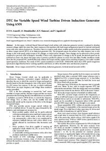
the three phase grid and rotor winding connected to the three phase grid by the use of back-to-back power semiconductor converter. Back-to-back is bi-directional semiconductor power converter consists of two pulsewidth voltage converter (converter connected to the rotor and converter connected to the grid side with voltage PWM inverter) and common DC link. The active and reactive power control system of the wind turbine is based on the theory of the induction machine vector control. That theory mean two-axis control described in three different reference frames.
Fig. 1: Wind turbine control system with DFIG The main rule of doubly-fed induction generator is conversion of power given from the wind turbine p t to the electric power psr and electric power delivery from DFIG stator to the electric grid. The wind power is extremely variable value depending about the wind speed, so doubly-fed induction generator from the wind turbine side has variable turbine torque m t and turbine angular speed ω t , i.e. generator torque m g and generator angular speed ωg . Simplified observed, electric grid has practically constant voltage u mabc and constant angular frequency ωs . Working conditions of the wind turbine based on fundamental equation that describes relationship of the angular frequencies of the stator and rotor speed ωs = ωg + ω r provide control system of the generator. Thereat, there are variable active rotor power p ra , stator losses p Cus and rotor losses p Cur . Stator active power psa determines set value of the reference active
Variable speed of the wind turbine generator with DFIG connected to electric grid
455
power p*a . So, rotor active power p ra is the consequence of reference value p*a for defined wind turbine power. Induction generator can work in super-synchronous mode ( p ra < 0 ), subsynchronous mode ( p ra > 0 ) and in synchronous mode ( p ra = 0 ). This paper describes dependence of the rotor power about wind turbine reference value power for constant wind speeds, i. e. constant wind turbine power. Static characteristic of the mechanical wind turbine power as a function of mean value of wind speed, used in wind turbine control system is shown in Fig. 2. For wind turbine powers p t > 750 kW and for wind speeds v w > 8 m / s , (the point C in Fig. 2.) it is possible ensure active power reference value by the doubly-fed induction generator control system, instead by rotor speed reference value [1]. For minimum wind speeds between points A and B in Fig. 2. reference value of active power is adapted as a function of minimum rotor speed of generator ωg min . In the case of rotor speed higher than ωg min and less than nominal rotor speed ωgn (interval between points B and C in Fig. 2.) the goal is to reach maximum speed of wind turbine.
3. MODELING OF THE ACTIVE AND REACTIVE POWER CONTROL SYSTEM OF THE DFIG WIND TURBINE 3.1 Modelling of the wind turbine drive train Dynamical model of the wind turbine describes the main parts of the wind turbine drive train system and induction generator that participate in interaction of the wind turbine with electric power system. By modelling of the drive train system it is need apply two-mass model. Accordingly, low frequency torsion fluctuations that dominate in dynamic behavior of the wind turbine can be recognized. Model of the drive train include inertias of the wind turbine, generator and gearbox which connect two rotating masses.
Fig. 2: Static characteristic of wind turbine mechanical power Pt as a function of mean wind speed
456
M. Zellagui
In this paper is chosen well-known two-mass model of the wind turbine and generator drive train. The grate mass of the wind turbine is represented by inertia J t , and the small mass of the induction generator is represented by inertia J g . The system of equations for simulation of the wind turbine drive train described in base quantities is: d ϑg d ϑ1 = ωg (1) = ωt , dt dt D νtt ωg + K νtt ϑg − D νtt ωt − K νtt ϑ t − m t d ωt = dt Tt − D νtt ωg − K νtt ϑg + D νtt ωt + K νtt ϑt + m g d ωt = dt Tg
Where: m t =
Pt ωt
(2)
Time constants of the wind turbine Tt and induction generator Tg , damping coefficient D νtt and shaft stiffness K νtt in equations system (1) are: Tt =
J t . ω2b Pb .i 2mk . p 2
D νtt =
D νt . ω2b Pb .i 2mk . p 2
J g . ω2b
[s ]
and
Tg =
[ pu ]
and
K νtt g =
Pb . i 2mk . p 2
K νt . ω b Pb .i 2mk . p 2
[s ]
[ pu ]
where i mk is gearbox ratio. Model input values are: ν m : Wind speed that defines wind turbine electric power upon Fig. 1. m t : Wind turbine torque m g : Electromagnetic torque of induction generator obtained from dynamic model of doubly-fed induction generator. The state variable of wind turbine dynamic model, whose at the same time output values, are: ϑ1 : Angle of the wind turbine axis, ϑg : Angle of the rotor of induction generator, ωg : Angular speed of induction generator.
Dynamic model of the wind turbine is composed of simplified quasi-stationary aerodynamic power of the wind turbine for constant wind speed and dynamic two-mass model of wind turbine drive train. 3.2 Dynamic model of the doubly-fed induction generator In the wind turbine system connected to the grid side with vector control of active and reactive power of DFIG, usually is used transformation of current, voltage and
Variable speed of the wind turbine generator with DFIG connected to electric grid
457
magnetic fluxes vectors of stator and rotor from original a b c reference frame into twophase rotating d q reference frame. Dynamic working modes of induction generator can be solutions of these equations define dynamic characteristics of the machine. The differential equations of the induction machine stator and rotor windings described in vector mode and in d q reference frame rotating by angular speed ωk are [4, 8]: u sdq = isdq . R s + u rdq = irdq . R r +
d Ψsdq dt d Ψrdq dt
+ j . ωk . Ψsdq
(3)
+ j . ( ωk − ω ). Ψrdq
(4)
where: ω : Electric angular rotor speed. Relationships between vectors of magnetic fluxes and vectors of stator and rotor currents are: Ψsdq = L s . isdq + L m . irdq Ψrdq = L m . isdq + L r . irdq
(5)
By substituting vector of stator current isdq and vector of rotor current irdq in
equations (3) and (4) with vectors of magnetic fluxes of stator Ψsdq and rotor Ψrdq become: 1 k + + j . ωk Ψsdq − r . Ψrdq T' dt Ts' r 1 d Ψrdq k u rdq = − s . Ψsdq + + j . ( ωk − ω ) Ψrdq T' dt Tr' r u sdq =
d Ψsdq
(6)
The equivalent diagram of the three-phase induction machine for dynamic states, given from equations (3) to (6), is shown in Fig. 3.
Fig. 3: Equivalent diagram of the induction machine for dynamic states
458
M. Zellagui
The parameters presented in equations (3) to (6) are: L's = σ . Ls , ks =
L'r = σ . L r ,
Lm L and k r = m , Ls Lr
Ts' =
σ =
1 − L2m , Ls . L m
Ls L and Tr' = r Rs Rr
Equation of electromagnetic generator expressed in base quantities is: mg =
kr
L's
(
. Ψsq . Ψrd − Ψsd . Ψrq
)
(7)
Current active and reactive power of induction generator is given from product of stator voltage vector and complex conjugate vector of stator current: p a = u sd . i sd + u sq . isq
(8)
p r = u sq . i sd − u sd . isq
(9)
Choice of the reference frame angular speed depends about selected structure of DFIG control system connected to the electric grid. Since, for control system realization of the converter connected to the rotor side and converter connected to the grid side required apply different reference frames it is selected α . β reference frame ( ωk = 0 ) as a basic frame for mathematical model of the electric components in power circuits of the wind turbine. The input values of vector equations (6) are vector of stator supply u sdq and vector of rotor supply u rdq . The state variables, at the same time output values, are vectors of magnetic fluxes of stator
Ψsdq
and rotor
Ψrdq . Other output values are
electromagnetic torque of generator and vectors of stator and rotor currents. Dynamic model of the doubly-fed induction generator is expressed in α . β reference frame, and all inputs and outputs of the model are expressed in that reference frame. The parameters of induction generator and base quantities are shown in appendix. The state variables and input/output values connecting mathematical models of the wind turbine drive train and doubly-fed induction generator are angular speed of generator given from dynamic model of the drive train (Eq. (1) and (2)) and electromagnetic torque of induction generator given from dynamic model of doubly-fed induction generator (Eq. 3, 6).
4. ACTIVE AND REACTIVE POWER CONTROL SYSTEM OF THE WIND TURBINE Vector control of active and reactive power control of wind turbine is decoupled power control of doubly-fed induction generator. In vector control of active and reactive power control of wind turbine is applied next reference frames:
Variable speed of the wind turbine generator with DFIG connected to electric grid
459
- induction generator is modeled in α . β reference frame that, by comparison with original abc reference frame, is at rest, - semiconductor power converter connected to the rotor side is modeled in d q reference frame; vector of stator magnetic flux is aligned to d-axis, - semiconductor power converter connected to the electric grid side is modeled in d q reference frame; vector of grid voltage is aligned to d-axis. Simulations in this paper have performed by constant DC link voltage, so mathematical model of the semiconductor power converter connected to the grid side have not token into consideration. Vector control system of active and reactive power of wind turbine is shown in Fig. 4. In the vector control system shown in Fig. 4. standard PI controllers with anti windup effect have applied. The rule of converter connected to the rotor side is independently control of active and reactive power control of induction generator. Active and reactive power control is not achieved directly, but power control is achieved through stator current vector. Control system connected to the rotor side work in dq reference frame aligned to stator magnetic flux vector Ψsdq = Ψsd . Rotor current vector in that reference frame is separated in i rd component that is in parallel with Ψsdq and i rq component that is orthogonal with Ψsdq . So, active power is controlled by i rq component, and reactive power is controlled by i rd component of vector irdq [5].
Fig. 4: Active and reactive power vector control system of DFIG
460
M. Zellagui
Outputs of the current controllers u*rd and u*rq (Fig. 4) are expressed in d q reference frame that is aligned to stator magnetic flux vector too. As induction generator model is in α . β reference frame, outputs of controllers assigned to the rotor side have to be transformed from α . β reference frame in d q reference frame. Mathematical model of control system connected to the rotor side can be derived by voltage equation of rotor (4) that described in scalar mode is: u rd = i rd . R r + u rq = i rq . R r +
d Ψrd − ωr . Ψrq dt d Ψrq dt
− ωr . Ψrd
(10) (11)
In equations (10) and (11) there are the parts: u 'rd = − ωr . Ψrq
(12)
u 'rq = ωr . Ψrd
(13)
which are shown in Fig. 4. [6, 7]. The parameters of active and reactive power PI controllers shown in Fig. 4 are: K pi , K pp gain constant and K ii , K pi integral constant. Input values are reference (sign *) and estimated (sign ^¨) active and reactive power of the wind turbine, vector of rotor current irdq , vector of rotor magnetic flux Ψrdq and speed of rotor ωg . Output is vector of rotor voltage u rdq .
5. SIMULATION RESULTS By the simulation is the goal to show distribution of wind turbine power (power on the axis of DFIG) into stator and rotor active power psa and p ra depending about reference active power p*sa . Rotor active power decides power of the back-toback converter located in the rotor circuit. By conversion of mechanical power of the wind turbine into grid electric power it is occurred the losses in DFIG cooper and losses of the converter in rotor circuit, which depend about active power reference value of the wind turbine. Responses of the stator and rotor active power psa and p ra , losses in cupper p Cu and rotor speed of generator ωg by step load of DFIG are shown in Fig. 5 to Fig 9. The all shown results are given for reactive power reference value q*sr = 0,0 pu . Figures 5 to 7 are performed by wind speed ν w = 14 m / s and by wind turbine power p t = 1,0 pu , and figures 8 and 9 are performed by wind speed ν w = 9 m / s and by wind turbine p t = 0,577 pu .
Variable speed of the wind turbine generator with DFIG connected to electric grid
461
By analysis of simulation results it is shown that active stator power psa good corresponding with reference value in the steady state mode. Power in the axis of doubly-fed induction generator p t is divided, in steady state modes, in active powers of stator psa and rotor p ra and in cupper losses p Cu of generator. In super-synchronous working mode (for ν w = 14 m / s in Fig. 5 and for ν w = 9 m / s in fig. 8), the wind turbine power is divided in stator active power psa and rotor active power p ra that DFIG deliver in electric grid.
Fig. 5: Time responses of psa , p ra , p Cu and ωg DFIG to step load: ν w = 14 m / s , p*sa = − 0,8 p u
Fig. 6: Time responses of psa , p ra , p Cu and ωg DFIG to step load: ν w = 14 m / s , p*sa = − 1,2 p u In sub-synchronous working mode (for ν w = 14 m / s in Fig. 6) generator deliver active power psa that is higher than wind turbine power p t . Because of that, generator takes rotor active power p ra from electric grid.
462
M. Zellagui
Fig. 7: Time responses of psa , p ra , p Cu and ωg DFIG to step load: ν w = 14 m / s , p*sa = − 0,94 p u In the case of reference power value p*sa = − 0,94 p u for ν w = 14 m / s in Fig. 7 and p*sa = − 0,55 p u for ν w = 9 m / s in Fig. 9 the active power of rotor, in steady state working mode, is just equal to zero. Therefore, in these steady state working modes, overall wind turbine power is distributed in electric grid over stator, and converters in rotor side are unloaded.
Fig. 8: Time responses of psa , p ra , p Cu and ωg DFIG to step load: ν w = 9 m / s , p*sa = − 0,45 p u By carefully analyses of cooper losses in stator and rotor for observed working modes it is shown that losses become higher for higher active power reference values. So, in sub synchronous working modes (Fig. 6), cooper losses of doubly-fed induction generator are much magnified. Active power of doubly-fed induction generator rotor p ra takes from electric grid, and it is unfavorable working mode. In super-synchronous working mode (Fig. 5 and 8) cupper losses are minimal, but converter in rotor circuit is loaded. Cupper losses at working modes with p ra = 0,0 pu (Fig. 7 and Fig. 9) are satisfactory, and load of power converter in rotor circuit is just equal to zero.
Variable speed of the wind turbine generator with DFIG connected to electric grid
463
Fig. 9: Time responses of psa , p ra , p Cu and ωg DFIG to step load: ν w = 9 m / s , p*sa = − 0,55 p u
6. CONCLUSION Shown dynamic model of the wind turbine generator connected to electric grid consist of dynamic model wind turbine drive train, model of doubly-fed induction generator and model of the active and reactive power vector control system. Active and reactive power control system is based on well-known vector control modeled in different reference frames. In this paper is presented issues of active power reference value choice. By simulation in program MATLAB/SIMULINK is shown that it is possible to ensure active power reference value by the control system located in rotor circuit of doubly-fed induction generator. From simulation results can be concluded that the best choice of active power reference value is in working mode with p ra = 0,0 pu . In that case, cooper losses are satisfactory, and load of converter in rotor circuit is just equal to zero. In future papers it would research options for application of rotor active power feedback instead of manual choice of reference value power in wind turbine generator.
REFERENCES [1] H.D. Anca, F. Iov, P. Sorenson and F. Blaabjerg, ‘Overall Control Strategy of Variable Speed Doubly-Fed Induction Generator Wind Turbine’, Nordic Wind Power Conf., Chalmers University of Technology, March 2004. [2] V. Akhmatov, ‘Analysis of Dynamic Behaviour of Electric Power System with Large amount of Wind Power’, PhD Thesis, Electric Power Engineering, Oersted-DTU, Technical University of Denmark, Denmark, April 2003. [3] DigSilent, ‘Dynamic Modelling of Doubly-Fed Induction Machine Wind Generators’, Technical Documentation, Germany, 2003. [4] P.C. Krause, ‘Analysis of Electric Machinery’, New York, McGraw-Hill, 1994. [5] J.G. Slootweg, S.W.H. de Haan, H. Polinder and W.L. Kling, ‘Aggregated Modelling of Wind Parks with Variable Speed Wind Turbines in Power System Dynamics Simulations’, Proceedings of the 14th Power Systems Computation Conference, SeviUq 2002.
464
M. Zellagui
[6] T. Sun, Z. Chen and F. Blaabjerg, ‘Transient Analysis of Grid - Connected Wind Turbines with DFIG After an External Short-Circuit Fault’, Nordic Wind Power Conference, Chalmers University of Technology, March 2004. [7] W. Hofmann and F. Okafor, ‘Doubly-Fed Full-Controlled Induction Wind Generator for Optimal Power Utilisation’, Proceedings of the Peds, 2001. [8] R. Gagnon, G. Sybille, S. Bernard, D.l Paré, S. Casoria and C. Larose,’Modeling and RealTime Simulation of a Doubly-Fed Induction Generator Driven by a Wind Turbine’, International Conference on Power Systems Transients (IPST’05) in Canada, June 19-23, 2005.
APPENDIX Wind Turbine Data Rated power Gearbox ratio
i mk = 89
Shaft stiffness
K vt = 12 ×107 Nm / rad
Damping coefficient
D vt = 3,5 ×10⁵ Nm / rad
Induction generator inertia
J g = 90 kgm 2
Wind turbine inertia
J t = 9 ×10⁶ kgm 2
Generator Data Rated power
Pgn = 2 MW
Ptn = 2 MW
Nominal voltage
U n = 690 V
Rated frequency Number of pole-pairs Stator resistance Rotor resistance Stator inductance Rotor inductance Magnetizing inductance
f n = 50 Hz p=2 R s = 0,048 pu R r = 0,018 pu Ls = 3,875 pu L r = 3,912 pu L m = 3,8 pu
Base System U b = 563 V , I b = 2366,66 A , ωb = 314 rad / s , Pb = 2000 kVA , Z b = 0,237 Ω , Ψb = 1,793 Wb , M b = 12739 N.m , Tb = 0,003185 s