Vol 6, Number 2, 2016 European Journal of Technic EJT
LABVIEW MODEL OF MEMRISTOR WITH NONLINEAR DOPANT DRIFT Muhammet Emin SAHIN *, Hasan GULER, Turgay KAYA Firat University *
Corresponding author;
[email protected]
Received: 1 November 2016; Accepted: 28 December 2016
Memristor as two terminal circuit element relating electrical charge and magnetic flux was proposed in 1971 by Leon Chua. But the first practical implementation has been realized by Willams’ group at HP laboratory in 2008. The memristor can provide new features in analog circuit design thanks to its different properties from resistor, capacitor and inductor. In this paper, we research memristor and depict a memristor model using LabVIEW. Firstly, a numerical solution of the memristor-based HP’s equations is derived for simulations. Then, memristor model for such system is presented. Finally the behavior and stability analysis of this system are researched and explained. Key words: memristor, LabVIEW, simulation 1. Introduction In electronics world, resistor, capacitor and inductor have been accepted as three fundamental circuit elements. These three elements define five out of six possible combinations of fundamental circuit variables: current (i), voltage (v), charge (q) and flux (φ) In 1971, Chua published a paper and theoretically presented the fourth element, memristor that defines the last possible combination. [1] In 1978 Chua and Kang extends the idea to memristive devices and systems. [2] Like a resistor, memristor creates and maintains a safe flow of electrical current across a device, but it can also remember the last charge that was flowing through it. This feature makes different memristor from the other circuit devices. The name, memristor was derived from the combination of memory and resistor. Since memristic properties are prominent only in nanoscale it evoked little research interest and remained dormant for three decades. A new wave of research was introduced in the field of circuit design in 2008 involving the memristor. Hewlett-Packard (HP) Labs in 2008 successfully fabricated a memristor. [3,4] A simple analytical model, experimental verification, and production of a titanium dioxide (TiO2) thin-film memristor has helped in advancing the research from then on. Memristor has drawn the worldwide attention after HP released its invention and after this year many studies are made very different fields. Owing to different properties, memristors are being found out for many potential applications in the areas of nonvolatile memory very-large-scale integrated (VLSI) circuit, digital image processing, artificial neural networks, and pattern recognition and signal processing. [5] In order to aid the design and simulation of memristor integrated circuits and systems, memristor models in various simulation environments are needed. Many memristor models have been proposed for simulation and characterization of memristor and memristor-based systems. Many different platforms 124
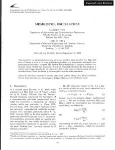
and languages such as SPICE, Verilog-A, MATLAB, and Simulink have been used for these purposes. [6-9] In this article, we focalize the memristor modeling with LabVIEW. Similar works have not founds up to, thus we assume that this is a different publications of the models and simulations described below. This paper is organized as follows. In methods, our nonlinear model of the memristor is presented and a formula is given in order to infer model parameters used physical parameters. In methods, measurements of simulation are defined. Final part of methods contributions of this paper are summarized. 2. Methods 2.1. Model of the Memristor from HP Labs Fig.1 shows that the physical model of the memristor, consists of a two layer thin film which is size D is 10 nm of TiO2, sandwiched between platinum contacts. One layer is doped with oxygen vacancies. Therefore it acts as a semiconductor. Undoped region has a non-conductor property. As a result of complicated material processes, the width w of the doped region is set depending on the amount of electric charge passing through the memristor. [4] The passage of the electric current in a particular direction, between the two regions’ boundary is moving in the same direction. RMEM is the total of the resistances of the doped and undoped regions, (1) (2)
ROFF and RON are the limit values of the memristor resistance which changes between w=0 and w=D. the two resistances’ ratio is usually given as 102 - 103.
Figure 1. HP’s memristor model
Figure 2. Undoped and doped fields in memristor
The Ohm’s law relation is applicable between the memristor voltage and current: 125
(3)
Dopant mobility is so-called µ and its value is 10-14 m2s-1V-1. In nanoscale devices, small voltages can yield enormous electric fields, these nonlinearities reveal themselves especially between the thin film edges, where the speed of the boundary between the doped and undoped regions gradually decreases to zero. This event, called nonlinear dopant drift, can be modeled by the so-called window function f(x) on the right side of (4). A concrete window function that would correspond to the memristor from HP labs is not existing at this moment. [6] The paper [6] proposes the window function in the following form: (4)
2.2. Memristor Modelling in LabVIEW We developed a behavioral model of a memristor at device level using the LabVIEW programme by following the mathematical equations presented before. We implemented HP’s memristor model to make it easy to comprehend and ready to be used in memristor based systems. 2.3. LabVIEW LabVIEW is a graphics-based software platform. The usage of program is going up in engineering applications. [10,12]. It ensures a visual platform for the development of algorithms. The design and operations of LabVIEW are depicted by some elements such as oscilloscopes and multimeter. So it is named a virtual instrument. It is not more difficult to use than the text-based programs. For this reason, the number of users is going up gradually. LabVIEW has two parts, the front panel and the block diagram. Block diagram corresponds to code writing part of text-based programming languages. The front panel is part of the program that was carried out. The program that is developed was created with links of graphical tools instead of writing code. [11,13] 2.4. Memristor Model in LabVIEW
Figure 3. Memristor model of LabVIEW 126
The mathematical model of blocks are given by (2) to (4) equations. (6)
∆R=ROFF – RON
(7)
Memristors’ characteristics are analyzed with control&simulation in LabVIEW model for numerical analysis is set equations which are given above. The model primarily includes of parameter control modules (constants and switches), input and output modules and internal operation modules (multipliers, adders and gain control modules). Switches are used to control the internal state variable x to vary between 0 and 1. Memristor parameters are fixed as RON = 100 Ω, ROFF = 16 kΩ, RINT = 11 kΩ, p = 10. These constant are used from literature. The external bias is V0 sin ω0t with V0 =1 V and f0=2 Hz. The simulation results are shown in Figure 4. State variable x varies in the range (0, 1); When adjusting the models in control&simulation platform it is necessary to observe the parameters which are set for the ODE solution. In this case we chose ode45 (Dormand-Prince) type of ODE solver which employs explicit Runge-Kuth method. Setting parameters were left implicit. ODE solver type leads to the right and exact conclusion. This model has the advantage of relative simplicity, speed and practical. 3. Results And Findings In order to show memristor characteristics, values of passive elements, and,are chosen to work firstly 1V input voltage at 2 Hz. Memristor model was simulated to test the behavior via using LabVIEW program. Memristor’s voltage and current are showed in fig. 4.
Figure 4. Relationship between memristor’s current (I) and voltage (V) 1V-2Hz
Fig. 4 indicates relationship between memristor’s current and voltage 1V- 2 Hz. The typical hysteresis loop in fig.5 shows that the memristor is a nonlinear element with a switching feature. Between high resistance and low resistance can be switched by the memristance. One of the most important memristors’ observed specialty is the existence of a pinched hysteresis that effect could be
127
represented by the i−v pinched hysteresis loop characteristic, which is a typical and critical memristor characterization, as Chua highlighted that ‘If it’s pinched, it’s a memristor’. [14] If we increase the frequency of the input signal, memristor behave as linear resistor.Fig.5 shows signal frequency is at 20Hz and Fig.6 shows that memristor’s loop turns the line chart at 200 Hz.
Figure 5. a) Relationship between memristor’s current (I) and voltage (V) 1V-2Hz b) Relationship between memristor’s current (I) and voltage (V) 1V-200Hz
Figure 6. Relationship between memristor’s charge and flux
Fig.6 shows relationship between memristor’s charge and flux 1V voltage and 2HZ frequency. Input voltage, memristor’s current and f(x) state function graphs are showed that figure 7 a, b, c, respectively. 4. Conclusion
In this paper, a memristor based equivalent circuit modelled as LabVIEW. When examining the effect on the equivalent circuits parameters and operating conditions are given equivalent circuits of memristor. The LabVIEW Control&Simulation model of the memristor, formed the basis of the state equations and boundary effects of modeling equations, presented results which are in concordance with a part of the by now other published works.
128
Figure 7. a) Input signal voltage of memristor b) current of memritor c) f(x) function’s graph
This operation is important to note the differences between the models some concrete regime’s behavior. Because the model of the memristor is designed such that it enables easy alteration of the nonlinear relations which describe the limit effects. Some different characteristics attract the attention of researchers. The result of this memristor are expected to be applicable and provide additional features analog system. References [1] L. Chua, Memristor-the missing circuit element, Circuit Theory, IEEE Transactions on 18 (1971), no. 5, 507 – 519. 1, 7, 9, 24 [2] Chua, L.O, M. S Kang, Memristive devices and systems, Proceedings of the IEEE, vol. 64, no. 2, pp. 209 – 223, Feb. 1976. [3] R. Williams, How we found the missing memristor, Spectrum, IEEE 45 (2008), no. 12, 28 –35. 2, 7, 9, 24, 28 [4] Dmitri B. Strukov, Gregory S. Snider, Duncan R. Stewart, and R. Stanley Williams, The Missing Memristor Found, Nature 453 (2008), 80–83. 2, 6, 7, 24 [5] Mazumder, P., Kang, S. M., & Waser, R. (2012). Memristors: devices, models, and applications. Proceedings of the IEEE, 100(6), 1911-1919. [6] Z. Biolek, D. Biolek, and V. Biolkova, SPICE Model of Memristor with Nonlinear Dopant Drift, Radioengineering 18 (2009), 210–214. 2, 8, 23, 25 [7] Yu Zhang, Xuliang Zhang, and Juebang Yu, Approximated spice model for memristor, Communications, Circuits and Systems, 2009. ICCCAS 2009. International Conference on, July 2009, pp. 928 –931. 2, 8
129
[8] M. Mahvash and A.C. Parker, A memristor spice model for designing memristor circuits, Circuits and Systems (MWSCAS), 2010 53rd IEEE International Midwest Symposium on, Aug. 2010, pp. 989 –992. 2, 8 [9] Joglekar, Y.N., Wolf, S. J. The elusive memristor: properties of basic electrical circuits. arXiv:0807.3994 v2 [cond-mat.meshall] 13 January 2009, p.1-24. [10] Aydin, Seda Guzel, Turgay Kaya, and Hasan Guler. "Wavelet-based study of valence–arousal model of emotions on EEG signals with LabVIEW." Brain Informatics 3.2 (2016): 109-117. [11] Guler H, Turkoglu I, Ata F (2014) Designing intelligent mechanical ventilator and user interface using LabVIEW. Arab J Sci Eng 39(6):4805–4813 [12] Guzel S, Kaya T, Guler H (2015) LabVIEW-based analysis of EEG signals in determination of sleep stages. In: Signal processing and communications applications conference (SIU), 23rd, IEEE, pp 799–802 [13] Guler H, Ata F (2014) The comparison of manual and LabVIEW based-fuzzy control on mechanical ventilation. J Eng Med 228(9):916–925 [14] L. Chua, “Resistance switching memories are memristors,” Applied Physics A, vol. 102, no. 4, pp. 765–783, 2011.
130