The work describes the various methods of memristor modeling and simulation in the MATLABï¸ and Simulinkï¸ environment. Previously published papers about.
The representation of memristor model in MATLAB® and Simulink® environment Sanzhar Askauly, Baktiyar Rakhmetov
Modeling in MATLAB
Abstract The work describes the various methods of memristor modeling and simulation in the MATLAB︎ and Simulink︎ environment. Previously published papers about memristors and their features are used as the foundation of the work. There are three various methods used in the MATLAB and Simulink for the differential and other equations formulation. The Airst equation uses the standard system core offer for the Ordinary Differential Equations solutions (ODE) in the m-‐Aile form. The second solution is the model construction in Simulink environment. The third method includes a physical modeling using the built-‐in SimscapeTM system. The results are the basic memristor characteristics and appropriate time courses. The characteristics of all models and their computer simulations are described in the paper.
Physical Memristor Model
First, memristor behavior is reproduced in the m-‐Aile form. This Aile has two functions with standard deAinition and corresponding ODE solution. In the Fig.4. source code of the memristor model is provided. Within the frame of the Memristor a MATLAB function is a key line is the chosen ODE solver which is the actual ODE numerical integration method. The solver of type ode23t shows that modiAied stiff/Trapezoidal method is used.
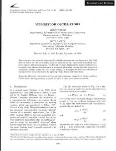
Simulink environment also contains Simscape block library, intended for multidomain modeling of physical systems. It also gives opportunity to simulate systems of various engineering Aields. Before approaching, the principle scheme is to be developed [3], presented in Figure. 8. Figure 8. Principle memristor scheme in Simscape
Figure 5. Memristor key time courses simulation
I. Introduction Initially, there were 3 basic passive elements – resistors, inductors and capacitors in the modern analogue electronics, see Figure 1. Based on the square symmetry, another element called memristor (memory resistor) was presented in 1971, according to [1]. Leon Chua summarizes the four elementary passive elements, follow Fig. 2. It contains of a direct connection between Alux and a charge. In other words, memristors show that resistance is dependent on a passing charge. As a results, it can be seen that memristors do not need any energy to keep data in terms of recording and reading. Therefore, the fourth passive element is able to hold information about the net amount of charge gone through. The Airst real memristor was built by Hewlett-‐Packard (HP) scientist in 2008 [2]. Its nano-‐part was made of titanium oxide with size of 10 to 30 nanometers hold between two platinum electrodes. The titan layer does not have oxygen atoms that make it to behave as a semiconductor. The other part acts as an insulator. The main functioning principle of memristor is that semiconductor layers width changes when current passes. The main purpose of the paper is to evaluate the memristor through modeling it in MATLAB and Simulink.
Figure 6. Elementary memristor characteristics simulation.
Figure 4. Memristor model in MATLAB
The initial value memristor resistance is given by Rinit . MATLAB ODE solver ode23t uses the function ODE_Memri_A as its parameters for output. The variables marked with [t, x] are returned back (2).
Input-‐output Model in Simulink Simulink environment is a better option when the memristor is to be modeled as an element of complex systems. Basically, the environment offers modeling the form of input-‐ output relationship. t is shown as device with the input of voltage and the output of current. Fig. 7. illustrated demonstrates a functional memristor model.
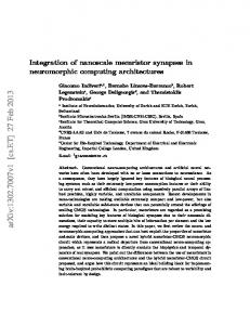
Figure 9 demonstrates the full physical memristor model. Some blocks serve for the mathematical model implementation, whereas a few other blocks are applied to convert between Simscape and Simulink environments as well as obtaining outputs on the oscilloscope. Apart from the blocks of drawing on the right, the physical model is exactly implementation of scheme of Figure 8. At the right side, the Current Sensor and Voltage Sensor blocks are needed to test the current and the voltage values. Moreover, PSS converters are Figure 9. used to interchange Simulink-‐ Physical memristor model in Simulink & Simscape Simscape library blocks so that the model can behave as entire system. Model in the Figure 9 is a representation of combined use of Simulink & Simscape. Therefore, the given system would be efAicient in terms of functionality. Similar to the model that was presented in Simulink, the integration is provided with 1/s integrator blocks. The Simscape AC Voltage Source block is a representation of harmonically variable voltage source accordingly.
(5) Figure 1. The passive element parameters de?inition.
Figure 2. The memristor and a passive elements quaternion
(6)
II. Mathematical Memristor Model The basic geometrical image of a manufactured memristor is represented in Fig.3. Thickness of the whole component is marked with D, the thickness of the doped layer with w. Its value is though dependent on the passing current (1) (2)
(7)
Figure 7. Memristor model in Simulink system
Fig. 3: Basic geometrical image of the memristor according to HP laboratories.
(3) (4)
Rmem – total resistance of doped and undoped region; μv = 10−14m2s−1V−1 x = w/D∈(0,1) RON and ROFF are resistances at w=0 and w=R f(x) – charge carrier transport window function
The relations illustrate (1) to (4) show the mathematical model of memristor that was discovered up to today.
The equations (5) and (6) are strictly followed by the arrangement of the blocks developed in Simulink. The initial condition of the integrator is deAined as in (7).. The other constants remain from the previous model.
The basic advantages of the input-‐output modeling in Simulink: ü Relative simplicity ü Descriptiveness ü Speed More attention is paid to blocks separation and simulation parameters conAiguration. The existing harmonic voltage source uses the same values as in the previous model. ConAiguration of Simulink environment takes place in the ODE solution parameters, which it to be set for ode45 (Dormand-‐Prince) type of ODE solver, which uses Runge-‐ Kuth method explicitly. Maximum step was set to 0.015 value. The simulation results are the same as the previous model.
Conclusion This work was based on the previous papers on memristor modeling. It sets goal to try various methods of modeling memristor in MATLAB and Simulink. As a result, a few models were obtained. First, m-‐Aile of source code solution to ODE was shown. Next, Simulink block diagram in terms of input-‐output model was built. It was then further developed with the help of Simscape block library, by adding variable resistor, necessary current and voltage sensors. To conclude, in the perspective the work that is planned is results checking by comparing obtained outputs with future SPICE model simulations.
Reference [1] Chua, L.O. Memristor -‐ the missing circuit element, IEEE Trans. Circuit Theory, 1971, vol, CT-‐18, no. 5, p. 507-‐519 [2] Strukov, D., Snider, G., Steward, D., Williams, R. The missing memristor found. Nature, 2008, vol. 453, 1 May 2008, p. 80-‐83. [3] Biolek, Z., Biolek, D., Biolkova, V. SPICE Model of Memristor with Nonlinear Dopant Drift. Radioengineering, 2009, vol. 18, no. 2, p. 210-‐ 214. ISSN 1210-‐2512.