Ellen M. Sentovich*, Horia Toma*, G rard Berry*. Th me 1 R seaux et syst ..... example, if R = f000;110;010;011g the condition is satis ed. Choosing the rst bit for ...
INSTITUT NATIONAL DE RECHERCHE EN INFORMATIQUE ET EN AUTOMATIQUE
Latch Optimization in Circuits Generated from High-level Descriptions Ellen M. Sentovich, Horia Toma, Ge´rard Berry
N˚ 2943 Juillet 1996 THE`ME 1
ISSN 0249-6399
apport de recherche
Latch Optimization in Circuits Generated from High-level Descriptions Ellen M. Sentovich* , Horia Toma* , Gérard Berry* Thème 1 � Réseaux et systèmes Projet MEIJE Rapport de recherche n�2943 � Juillet 1996 � 19 pages
Abstract: The authors address the problem of e�ciently exploring good latch/logic tradeo�s for large designs generated from high-level speci�cations. They describe algorithms for reducing the number of latches while controlling the size of the intermediate logic. Key-words: register removal, sequential optimization, state assignment, high-level synthesis, reachable states computation
(Résumé : tsvp)
Acknowledgments: This work was supported in part by the National Science Foundation under grant INT-9505943, and the French GENIE MESR INRIA project. * École Nationale Supérieure des Mines de Paris, Centre de Mathématiques Appliquées 06904 Sophia-Antipolis, FRANCE, Email : {ellen}{toma}{berry}@cma.cma.fr Unite´ de recherche INRIA Sophia-Antipolis 2004 route des Lucioles, BP 93, 06902 SOPHIA-ANTIPOLIS Cedex (France) Te´le´phone : (33) 93 65 77 77 – Te´le´copie : (33) 93 65 77 65
Optimisation du nombre des registres dans les circuits générés à partir de langages de haut niveau Résumé : Les auteurs abordent d'une façon e�cace le problème de la recherche d'un compromis
entre le nombre des registres et la taille de la logique dans le cas de circuits générés à partir des descriptions de haut niveau. Ils décrivent des algorithmes qui réduisent le nombre de registres tout en contrôlant la taille de la logique supplémentaire. Mots-clé : minimisation du nombre des registres, optimisation séquentielle, recodage d'états atteignables, synthèse de haut niveau, calcul des états atteignables
Latch Optimization in Circuits Generated from High-level Descriptions
3
In a gate-level description of a �nite state machine (fsm), there is a tradeo� between the number of latches and the size of the logic implementing the next-state and output functions. Typically, an initial implementation is generated via explicit state assignment or translation from a high-level language, and this tradeo� is only lightly explored via logic synthesis from that point on. We address the problem of e�ciently exploring good latch/logic tradeo�s for large designs generated from high-level speci�cations. We describe algorithms for reducing the number of latches while controlling the size of the intermediate logic. We use these algorithms to generate good �nal implementations (e.g., hardware or software) and good intermediate representations (e.g., for symbolic state traversal). We demonstrate the e�cacy of our techniques on some large industrial examples.
1 Introduction In a gate-level description of a �nite state machine (fsm), there is a tradeo� between the number of latches and the size of the logic implementing the next-state logic. This tradeo� can be exploited at two levels: during generation of the initial implementation, and during subsequent logic optimization steps.
1.1 Background
State assignment is the generation of a state encoding and an initial latch/logic implementation from a higher level in the design process. To date, primarily two approaches have been used:
Explicit state assignment begins from an explicit state transition graph and chooses a minimum-
latch encoding while minimizing the size of the combinational logic [DBSV85, VSV90, Har61]. State assignment from high-level languages chooses an encoding according to the delay statements in the speci�cation, relying on logic synthesis to later optimize the gate-level implementation [BT93]. Explicit state assignment is impractical for large designs, and despite sophisticated techniques for determining an optimal assignment, it can produce results far worse than hand-coded implementations. Furthermore, explicit state assignment programs have not targeted greater-than-minimum-latch implementations. With current technology (e.g. FPGAs), it is no longer necessary to minimize the number of latches and doing so often produces prohibitively large combinational logic. One-hot encoding can also be applied to an explicit state graph, where one latch is used for each state. The resulting logic will be small and fast since the states do not need to be encoded and decoded. However, the number of latches is huge, and a one-hot implementation can be a di�cult starting place for logic synthesis. Automatic techniques for reducing the number of latches in a one-hot implementation to produce a good tradeo� have not been resoundingly successful. State assignment from high-level languages is typically done by a statement-by-statement translation, which results in a natural insertion of registers at the delay statements in the description. This is a good starting point for logic synthesis, but results in far more latches than are required to implement the design [BT93]. Even if the number of latches is not important for the �nal implementation, too many can drastically reduce the e�ciency of many synthesis and optimization algorithms (e.g., symbolic state traversal). After state assignment, the latch/logic tradeo� can be explored via logic optimization. Standard techniques, e.g., extracting common factors, function simpli�cation, and retiming, may result in some latch/logic rearrangement, but largely the state assignment is �xed and optimization only improves the implementation for the given assignment. The goal of retiming and resynthesis [MSBSV91] was to jointly optimize latch positions and combinational logic, but the optimization potential was too limited by the initial state assignment. RR n�2943
4
Ellen M. Sentovich, Horia Toma, Gérard Berry
Removal of redundant latches has been done ubiquitously. The term �redundant latches� itself is used ubiquitously with a variety of meanings: latches that do not fanout to a primary output, latches that are constant in the entire state space, latches that are constant in the reachable state space, latches that are equivalent to other latches, and other more sophisticated de�nitions. We do not consider simple redundant latch removal here (latches that do not fanout, latches that are constant) as the results are straightforward. Equivalent state variable identi�cation and removal has been done as part of several works (e.g., [SSM+ 92, vEJ95, QCC+ 95]). With current BDD and symbolic traversal techniques, this also is a simple operation. A more robust algorithm for single latch removal was published in [LN91]. It is directly relevant to our single latch removal algorithm described in Section 3.1 and is treated more thoroughly in that section. It is exact (precisely for replacing a single latch with logic), and far too expensive when the number of latches exceeds the minimum (log2 (reachable ? states)) even for small circuits. In [QCC+ 95], a more general technique for re-encoding �nite state machines was given. While some of the work there is relevant to ours (e.g., controlling the size of the encoding/decoding logic), the target was quite di�erent. The goal of that re-encoding was to try to match the encodings of two di�erent but similar machines in order to speed up symbolic traversal.
1.2 Our Approach
A complete exploration of the latch/logic tradeo� is certainly not feasible or necessary. Nonetheless, a su�ciently rich choice of solutions should be available, especially with the variety of implementations found in today's technology. For example:
� one may target an implementation in hardware or software � a hardware implementation may be targeted to a �nal custom design or an FPGA board for
emulation � the current speci�cation may be a preliminary one (not intended for implementation) and used only for veri�cation of functional properties. In the above three cases, the optimization criteria are quite di�erent. We focus on e�cient exploration of the latch/logic tradeo� for a design generated from a high-level speci�cation. In particular, we begin with designs generated from Esterel descriptions. The initial encoding (generated by the Esterel compiler), while a natural one with respect to the behavior of the design, contains many redundant registers. We develop algorithms for removing redundant registers. We target the algorithms to work well on large designs, and to remove registers as cheaply as possible (i.e., to easily discover redundant registers, to be able to easily replace them with a minimum amount of additional logic). We generate optimal solutions considering �nal implementation cost and/or e�cacy of the intermediate representations. Our key results include the following:
� Our algorithms are e�cient enough to provide a signi�cant choice of implementations regarding
the latch/logic tradeo� for very large circuits. No other results in this direction have been published thus far that we are aware of.
� By applying simple (easy to compute) heuristics for latch reduction, we get very close to the
minimum number of latches possible on a given reachable state set. In almost all our examples we obtained a �nal number of latches less than or equal to log2 jRj + 1, where R is the set of reachable states.
� Because we work incrementally from an initial implementation taken from a high-level language,
and we strive to preserve the given structure, the size of the resulting logic remains tractable even as we approach the minimum number of latches.
INRIA
Latch Optimization in Circuits Generated from High-level Descriptions
5
� Our results for maximum latch removal, in terms of area of the resulting logic, compare very
favorably to those obtained by the traditional �robust� technique of extracting the state transition graph, running an explicit state encoding program, and performing logic optimization on the result: we usually obtain a smaller implementation in much less time. Furthermore, we observed a blow-up in the area of the initial implementation after state assignment (resulting in very long logic optimization run-times) which we do not experience with our incremental techniques. We could only make this comparison on relatively small examples, as the explicit state transition graph is expensive to compute.
� Run-times for the latch removal algorithms are insigni�cant. The reachable state set is computed
initially, and all subsequent latch redundancies are determined in a comparatively trivial amount of time from this set.
2 Overview of the Technique We apply heuristic techniques to successively remove redundant latches while controlling the size of the combinational logic. A complete latch removal technique could be implemented by extracting an explicit state transition graph, performing exact state minimization, and running a state assignment program to generate a minimum-latch encoding. This is far too expensive and yields no insight to the latch/logic tradeo�. We instead successively remove latches using a subset of the information that is used in the aforementioned complete scheme. (For example, we consider reachable states, but not equivalent states.) In this realm, a general heuristic procedure might be: 1. Compute the BDDs for the latches, the outputs, and some auxiliary functions (e.g., equivalent states, reachable states, controllability/observability information from the environment). 2. Apply algorithms for removing latches such that the sequential behavior is unchanged with respect to the environment described by the auxiliary functions. 3. Iterate, removing as many latches as possible, or as many latches as desired given constraints on the size of the combinational logic.
2.1 The General Algorithm
As we �nd this scheme still too expensive for industrial applications, and more robust than necessary as we demonstrate experimentally, we choose the simpler scheme: 1. Compute the reachable states of the machine. 2. Determine a set of latches which may be easily removed while preserving the reachable state set. 3. Among these, choose a set of latches to remove based on a cost estimate; remove latches, add logic, and optimize. 4. Iterate, removing as many latches as possible, or as many latches as desired given constraints on the size of the combinational logic.
It is important to note that at each one-latch-removal step, for each of our proposed algorithms, we reencode states by considering state pairs which can be easily merged. This is not a general re-encoding: we pair each reachable state with an unreachable state, and give each pair a single new encoding. The pair/merge operation is done in such a way that � it is computationally easy to determine the pairings RR n�2943
6
Ellen M. Sentovich, Horia Toma, Gérard Berry M’
M Out
In
Out
In
C n
C n
L
n
n
Y D
L’ m
m
Y
E
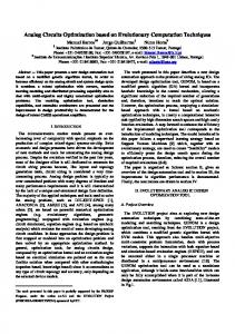
Figure 1: General Circuit Transformation
� it is inexpensive in BDD size and logic size to perform the mergings and update the reachable
states � the existing logic is preserved as much as possible as it contains valuable information on the structure of the circuit. In this way, the computations required remain tractable for our very large circuits, and the resulting additional combinational logic (which is usually the most limiting factor in incremental re-encoding algorithms) is controllable. It is very important to note that the transformation is proven to preserve behavior on the reachable state set and remains correct for every over-approximation of the reachable state set. Therefore it could be used in conjunction with e�cient techniques for approximate reachability analysis [CHM+ 94].
2.2 Circuit Transformation
The transformation is illustrated in Figure 1. The original FSM is M and the transformed one is M 0 . We call L = flk j 1 � k � ng the set of latches of M . A transformation will remove latches with indices in a set I . For convenience, we keep the same indices for the remaining latches in M 0 : L0 = flk0 j 1 � k � n; k 62 I g, and we assume that L0 has m latches. The next state vector for L in M is generated by C and called Y . In M 0 , the encoding function E has type B n ! B m and it is given by a vector of functions Ek : B n ! B , 1 � k � n; k 62 I . The decoding function D has type B m ! B n and is given by a vector Dk : B m ! B , 1 � k � n. Let R � B n (resp. R0 � B m ) be the set of reachable states in M (resp M 0 ), and let R : B n ! B (resp. R0 : B m ! B ) denote the characteristic function of R (resp. R0 ). Thus r 2 R implies R(r) = 1. Let r0 and r00 denote the initial states of M and M 0 . In this context we say that M is equivalent to M 0 if r0 = D(r00 ) and D(E (r)) = r for all r 2 R. This is the property our transformations will satisfy. Functions will be represented by polynomials or BDDs. The input variables will be consistently called yk for E , lk0 for D, lk for R, and lk0 for R0 . If F denotes a polynomial or BDD over a set of variables X and if Y is another set of variables where jX j = jY j, we denote by F [Y=X ] the result of the substitution of the xk by the yk , and F [Y =X ] the result of the substitution of the xk by the complements yk . We respectively denote by Fx and Fx� the positive and negative cofactor of F with respect to x.
3 Algorithms In this section, several algorithms for latch removal are described. In summary: 1. single-latch removal: determine which latches can be removed individually and replaced by a combinational function of the other latches.
INRIA
Latch Optimization in Circuits Generated from High-level Descriptions
2.
2-by-1
4.
n-by-(n-1)
7
: determine pairs of latches that can be removed and replaced by a single latch whose input is a combinational function of the other latches. 3. one-hot-3-by-2: search for a one-hot encoding and replace every three latches by two latches and a combinational function. each latch.
: replacement of n latches by n ? 1 latches with a new combinational function for
In the following sections, each is speci�ed precisely according to � the condition under which latches are removed
� the logical transformation required in the circuit, i.e. the speci�cation of D and E in Figure 1
[Note: There are many choices in the functions to implement. We have chosen and described one for each algorithm. The reasons for each choice and its subsequent e�ects on optimization are further described in Section 4.]
� a proof that the transformation is valid [Note: The new initial state is trivially computed from the encoding function E and hence not discussed further.]
� a brief description of the algorithm [Note: In every case, R is incrementally and e�ciently updated for further computations and iterations.]
3.1 Transformation single-latch
Single latch removal �nd and replaces latches that can be substituted by a combinational function of the other latches.
Condition: A single latch li can be replaced by a combinational function of the others if Rl �R�l = 0
(1) This condition was originally given in [BCM90]. Its satisfaction implies that li does not distinguish any reachable states; the re-encoding will couple each reachable state of the form l1 l2 : : : li?1 0li+1 : : : ln with the unreachable state l1 l2 : : : li?1 1li+1 : : : ln to produce the state l10 l20 : : : li0?1 li0+1 : : : ln0 and similarly for 1=0. In general, a subset of the latches will each satisfy this condition. Once a single latch is removed, the remaining subset of removable latches may change. We apply heuristic techniques, as described in the algorithms below, to determine which latches to remove. In [LN91], an exact branch-and-bound algorithm is used to determine the maximum number of single latches that can be removed. While the paper indicates that the bounding heuristics are powerful and the exact result is obtained in a reasonable amount of time, the experiments were only performed on small examples: the largest reduction in number of latches is 5 and the largest total number of latches is 21. Our designs have 10's and 100's of latches, with many redundant latches. The exact algorithm is far too expensive, and we have empirically observed results that nearly match it with the single-latch algorithms. Furthermore, we reduce the number of latches even further with the algorithms described in the sequel. i
i
Transformation: The latch li is removed and the logic for functions D and E are added, where E is de�ned by Ek (Y ) = yk for k = 6 i. For D, we set Dk (L0) = lk0 for k 6= i and Di (L0 ) = Rl [L0 =L] (2) i
RR n�2943
8
Ellen M. Sentovich, Horia Toma, Gérard Berry
M R)
single-latch-1( , { _temp = ; removed_list =
R
R
�;
/* Find and remove latches. */ while (1) { best_latch_cost = ; foreach latch i { if is_removable( _temp, i ) { li = compute_cost( i , _temp); if ( li < best_latch_cost) { best_latch_index = ; best_latch_cost = li ; } } } if (best_latch_cost ) break; = best_latch_index; _temp li _temp; removed_list removed_list i; } if (removed_list ) return;
l
C
1
R
l
l R
C
/* By condition (1) */
i C
�1
i
R
9 R
[l
��
/* Compute
D
and modify
M.
*/
R_new = R; foreach li 2 removed_list { Di = R; foreach lj 2 removed_list, j 6= i Di 9l Di ; j
}
Dil [L0 =L]; add_logic(M , Di ); remove_latch(M , li = 0);
Di } }
{
i
R_new
/* By transformation (2) */
9l R_new; i
R R_new; Figure 2: Transformation single-latch: Algorithm 1
Proof: Let l 2 R. If j 6= i, then Dj (E (l)) = Ej (l) = lj . Let li = 0. Then since R = li �Rl + �li �R�l , and R(l) = 1, we have R�l (l) = 1. With condition (1) this implies Rl (l) = 0, and thus Di (E (l)) = Rl (l) = 0 = li . Similarly for li = 1. 2 i
i
i
i
i
Two algorithms were implemented for single latch removal; the pseudo-code is given in Figures 2 and 3. INRIA
Latch Optimization in Circuits Generated from High-level Descriptions
9
M R
single-latch-2( , , bound) { cost_bound = bound; while (1) { removable_list = ; removed_list = ; foreach latch i { if is_removable( _temp,
l
Di = Rl
�
�
R
li )
{
/* By condition (1) */ /* By transformation (2) */
D
i
if (compute_cost( i ) < cost_bound) removable_list removable_list }
[ (li ; Di );
} if (removable_list ) return; sort_by_cost(removable_list); foreach latch i removable_list { if (still_can_be_removed(removed_list,
��
l 2
Di = Rl
i
M Di ); M , li = 0);
add_logic( , remove_latch( removed_list li ;
R 9R
}
removed_list
li ))
{
[ li ;
} } modify_cost(cost_bound);
}
Figure 3: Transformation single-latch: Algorithm 2
Algorithm 1: greedily selects and removes one latch at a time based on a cost function related to
the potential for removing other latches. We use the branching heuristic of [LN91], so compute_cost sets Cl = jRj? abs(jRl j?jR�l j), where jRj is the onset size of the BDD R. The absolute value term is highest for those latches with the most potential for distinguishing states. By selecting the latch with the lowest Cl , we leave the latches with the highest potential, and thus heuristically maximize the chances of removing more latches. Furthermore, this heuristic implies a minimum number of minterms that are changed in the encoding space, which we observe to help control the size of the overall logic. After selecting the latch, R is updated as though the latch had already been removed, and the process is iterated. After a set of latches that can be removed simultaneously have been computed, they are removed and replaced by combinational logic that depends only on the remaining latches. This algorithm computes a maximal removable set, and hence iteration is not necessary. Note that upon removing the latch, the output variable implementing the input of the latch is set to 0, which results in simpli�cation of the combinational logic C . In addition, each Di is computed directly from the initial R by smoothing all the other variables that will be removed: if l1 ; l2 ; : : : lj are simultaneously removable, D1 = (9l2 ; 9l3 ; � � � 9l :Rl1 )[L0 =L], and similarly for D2 ; D3 ; : : : ; Dj . Furthermore, the operations can be performed in any order since 9 is commutative and 9 and cofactor commute. Alternately, R could be updated as each variable is removed, and the next Di computed from the updated R. This latter technique requires less computation at each removal, but creates functions that depend upon variables that will be eventually removed and hence increases the levels of logic. As we strive to control size and depth of the logic and as computation time is not signi�cant, we prefer the former method. i
i
i
i
j
Algorithm 2: selects a set of latches according to a cost bound that is based on the BDD size.
returns the number of support variables in the BDD for Di , and as such is an estimate of both BDD size (for manipulation) and �nal implementation size (resulting logic for D). Of course, the number of BDD support variables is not at all a tight measure of implementation size; nonetheless, compute_cost
RR n�2943
10
Ellen M. Sentovich, Horia Toma, Gérard Berry
M R
2-by-1( , ) { foreach latch i { compute_cofactors( , i ); li , �li foreach latch j , = { compute_cofactors( li , j ); li lj , li �lj compute_cofactors( �li , j ); �li �lj �li lj , if is_removable( li lj , /* By condition (3) */ �li lj , li �lj , �li �lj ) { compute_ ; /* By transformations (4) (5) */ j , i, j add_logic( , j , i , j ); remove_latch( , i ); �j ( � � + l l ) + j ( � + � ); li lj i j li lj li lj } } } }
R
R R R
l
R R
R l
l j6 i
R
R
R
R R
R
l l
E D D DE M E D D M l R l R R l R R
Figure 4: Transformation 2-by-1: Algorithm there is a correlation and at this level it is very di�cult to estimate implementation size without further synthesizing the design. Since a set of latches is selected according to their individual removable condition in R, there is no guarantee that they can be removed simultaneously. This condition is checked during latch removal in the second part of the algorithm. Di must be recomputed as well to ensure that it depends only on remaining latches. The entire process is iterated with an increasing cost bound.
3.2 Transformation 2-by-1
Condition: Two latches li and lj can be replaced by a single latch lj0 if Rl l �R�l �l + Rl �l �R�l l = 0 i j
i j
i j
(3)
i j
The satisfaction of this condition implies that there is again a valid pairing of reachable states and unreachable states. The re-encoding will couple each reachable state l1 l2 : : : li?1 0li+1 : : : lj ?10lj +1 : : : ln with the unreachable state l1 l2 : : : li?1 1li+1 : : : lj ?1 1lj +1 : : : ln to produce l10 l20 : : : li0?1 li0+1 : : : lj0 ?1 0lj0 +1 : : : ln0 . That is, li lj = 00 or 11 is replaced by lj = 0 and li lj = 01 or 10 is replaced by lj = 1.
Transformation: If li and lj satisfy the above condition, one can remove li and set �
8 < :
( ) = yi �y�j + y�i �yj ( ) = yk ; k 2 = fi; j g
(4)
Ej Y
Ek Y
( 0 ) = lk0 ; k 2 = fi; j g 0 + �lj �Rli lj )[L0 =L] Di (L ) = (lj �Rl � l i j 0 0 � Dj (L ) = (lj �R� li lj + lj �Rli lj )[L =L] Dk L
(5)
Proof: Let l 2 R. If k 6= i and k 6= j , then Dk (E (l)) = Ek (l) = lk . Let li = lj = 0 in l. Then since R = li �lj �Rl l +�li �lj �R�l l +li ��lj �Rl �l +�li ��lj �R�l �l and R(l) = 1 we have R�l �l (l) = 1. With the �rst term of condition (3), this implies Rl l (l) = 0. This, with Ej (l) = 0, implies Di (E (l)) = Ej (l)�Rl �l (l) + Ej (l)�Rl l (l) = 0 = li and Dj (E (l)) = Ej (l)�R�l l (l) + Ej (l)�Rl l (l) = 0 = lj . Similarly for li lj 2 f01; 10; 11g. Thus, D(E (l)) = l for each reachable state l. 2 i j
i j
i j
i j
i j
i j
i j
i j
i j
i j
INRIA
11
Latch Optimization in Circuits Generated from High-level Descriptions
Algorithm: The pseudo-code for the algorithm is shown in Figure 4. Each latch pair is examined and replaced by a single latch if possible. Note that in this case, the input yi of the removed latch li cannot be set to 0 because Ej depends on it. Therefore, there is no subsequent logic reduction in C .
3.3 Transformation one-hot-3-by-2
This transformation is very speci�c to one-hot encoded designs. Note that if the single latch removal algorithm is applied to a one-hot-encoded design, only one latch can be removed (even if the exact algorithm is applied) even though the design has jLj latches and the minimum is log2 jLj. This algorithm �rst searches for part of the encoding space that is one-hot encoded. It then replaces every three latches by two in this part of the encoding.
Condition: The condition for a latch yi to be one-hot-encoded is given by Rl
i
=
n Y � j =1
lj
j 6=i
Transformation: Each group of three latches li, li+1, li+2 can be replaced as follows: 8 Q �l0 D (L0 ) = li0 +1 �li0 +2 � n =1 8 > i k > > > k6=Qi;i+1;i+2 < Ei+1 (Y ) = (yi �y�i+1 + y�i �yi+1 )�y�i+2 < 0 0 0 0 Di+1 (L ) = li+1 �l� i+2 � Q �lk i+2 (Y ) = (�yi �yi+2 + yi �y�i+2 )�y�i+1 >E : > D (L0 ) = l�0i+1 �li0+2 � �lk0 > Ej (Y ) = yj j 2= fi; i + 1; i + 2g > : Dij+2 = fi; i + 1; i + 2g (L0 ) = lj0 j 2 k
Proof and Algorithm: We omit the proof for brevity, and we do not describe this algorithm in detail as it is a specialized heuristic, and straight-forward to implement.
3.4 Transformation n-by-(n-1)
The n-by-(n-1) algorithm considers the entire encoding space when searching for a state-pair merging, rather than restricting to merging across a plane or a small cube (as the case for single and 2-by-1). The algorithm has two parts. First, the encoding is modi�ed (without removing latches) by clustering the existing encodings toward the all-0 encoding. This is called migrate-states. Next, the resulting encoding is checked to see if each reachable state can be paired with its mirror state (all variables complemented).
3.4.1 Transformation migrate-states Condition: The condition that some encodings can be shifted toward the origin is given by (6) 9li s:t: Rl �R�l =6 0 No registers are removed at this step. The reachable states in li �Rl �R�l are re-encoded as �li �Rl �R�l . Since �li �Rl �R�l 6� R, this transformation safely maps a state in the reachable set to an unused encoding i
i
i
i
i
i
i
i
(in the unreachable set).
Transformation: Given li that satis�es (6), the machine is re-encoded as follows: ( Ej (Y ) = yj ; j = 6 i E (Y ) = (li �Rl �R�l )[Y=L] i ( 6 i Dj (L0 ) = lj0 ; j = 0 0 Di (L ) = li + (Rl �R�l )[L0 =L] i
i
RR n�2943
(7)
i
i
(8)
12
Ellen M. Sentovich, Horia Toma, Gérard Berry
Proof: Let l 2 R. If j 6= i, then Dj (E (l)) = Ej (l) = lj . Let li = 0 in l. Since R = li �Rl +�li�R�l , and R(l) = 1, we have R�l (l) = 1. With li = 0 ) Ei (l) = 0, Di (E (l)) = Ei(l) + Rl (l)�R�l (l) = 0. Let li = 1. The Shannon cofactor and R(l) = 1 imply Rl (l) = 1. Then, Ei (l) = li �Rl (l)�R�l (l) = R�l (l). Finally, Di (E (l)) = Ei (l) + Rl (l)�R�l (l) = R�l (l) + R�l (l) = 1. 2 i
i
i
i
i
i
i
i
i
i
i
i
i
Algorithm: greedily moves the encodings towards the origin in the Boolean space. The algorithm is
implemented simply by iterating over the latches, checking the condition and performing the transformations if possible. The motivation is that the subsequent fold-states operation can be performed if all the reachable states are Hamming distance d n2 e ? 1 of the origin1 . We could choose any point in the Boolean space around which to cluster the encodings, but the all-0 encoding is a good choice for Esterel circuits (and, we believe, for others generated from high-level descriptions). The reason is that, while the initial encodings are not one-hot, they are close to one-hot, and �group-hot�; as such they contain many 0's. migrate-states can add an exorbitant amount of logic, so rather than iterating to completion, we check the fold-states condition at each iteration and stop when it is satis�ed. The reachable states are updated after each latch is visited as follows:
R0 = li0 �(Rl �R�l )[L0 =L] + �li0 �(R�l + Rl �R�l )[L0 =L] i
i
i
i
i
3.4.2 Transformation fold-states
The re-encoding is done by choosing a latch li , and for each state encoding l, if li = 1 in l the encoding is unchanged, while if li = 0 the other state variables are inverted. The latch li is then removed. For example, if R = f000; 110; 010; 011g the condition is satis�ed. Choosing the �rst bit for the removed latch li , the new encoding is R0 = f11; 10; 01; 00g.
Condition: The condition under which the states can be merged is given by � ]�R = 0 R[L=L
(9)
Transformation: The transformation removes register li and sets �
( ) = y�i �y�j + yi �yj ;
Ej Y
( 0 ) = Rli [L0 =L] 0 0 0 Dj (L ) = lj �Di + � lj �Di ;
(10)
=i
j 6
Di L
(11)
=i
j 6
Proof: Let l 2 R. Let li = 0 in l. The Shannon expansion of R(l) and the fact that R(l) = 1 imply � ](l) = 0. Also R[L=L � ] = (li �Rl + �li �R� )[L=L R�l (l) = 1, and since condition (9) holds, R[L=L l � ]= � � � � � li �(Rl [L=L]) + li �(R�l [L=L]), so Rl [L=L](l) = 0. Therefore, Di (E (l)) = Rl [L=L](l) = 0 = li . Finally, because li = 0, Ej (l) = �lj for all j = 6 i. So Dj (E (l)) = Ej (l)�Di(l)+Ej (l)�Di(l) = Ej (l) = lj for each j = 6 i. i
i
i
i
i
i
i
Similarly for li = 1. 2
Algorithm: is implemented directly from (10) and (11). The reachable states are updated as follows: R0 = Rl [L0 =L] + R�l [L0 =L] i
1
i
This is a su�cient but not necessary condition. INRIA
13
Latch Optimization in Circuits Generated from High-level Descriptions
3.5 Comments on the Algorithms
It must be emphasized that in selecting algorithms and heuristics, we do not focus primarily on traditional logic optimization metrics. Our goals while exploring the latch/logic tradeo� are instead to
� maintain the initial existing logic structure to the extent possible, as it re�ects the structure given by the high-level description,
� use metrics that relate to the perform of our algorithms and to the size of the D, E logic which we have the most control over: we try not to overly pessimize logic synthesis,
� leave the logic optimization to existing tools that are specialized for this purpose.
Heuristics
The most important heuristic that we have not described is related to don't care conditions for selecting D and E . In each case, there is actually a set of combinational functions that can be used, not just a single one. The set arises from the use of the unreachable states as don't care conditions; we have not indicated this choice in our description of the D and E functions. For example, in the single-latch algorithm, any function that satis�es Rl � Di � Rl + R�l would be correct. We experimented with di�erent choices, and found that the functions were small enough that this degree of �exibility was not useful at this level. Furthermore, since it arises solely from the reachable state set, the same information can be used instead in subsequent logic optimization. There are many other heuristics that can be employed for selecting a latch, for minimizing the BDDs, for minimizing the implementation, for optimizing algorithm performance, etc. We focus on �nding good implementations and exploring a reasonable subset of the latch/logic tradeo� given the available tools (state-of-the-art BDD technology, logic optimization, etc.) for the designs in our domain, rather than attempting to implement any exact algorithms or thoroughly test a large set of heuristics whose �nal value is di�cult to measure. We tested a number of heuristics (especially for selecting D and E ) and our choices in function implementation re�ect the results of these experiments. i
i
i
Other similar algorithms
Note that the 2-by-1 is a generalization of the single latch removal algorithm, which can be further generalized to replace 3 registers by 2, etc. We found that such a successive generalization did not improve the results su�ciently to justify its rapidly increasing cost. (Note that the n-by-(n-1) algorithm described above is not a generalization of 2-by-1).
Completeness
The single_latch algorithms are complete in that when they are �nished, no single latches can be removed while maintaining the same reachable state set on L. No claims are made about removing several latches by this criteria. Transformation 2-by-1 is not complete in that it may be possible for two latches to be replaced by one latch with additional combinational logic and not replaced by this algorithm. Similarly, the n-by-(n-1) algorithm is not complete.
4 Implementation and Results Experiments have shown that �nding a good latch encoding before performing optimization is a very di�cult problem, yet an important one as the encoding strongly e�ects subsequent optimization. We know that a log2 jRj encoding usually implies exorbitant combinational logic, but given a particular encoding we cannot predict what the size of the combinational logic will be. The same intuition applies to the tradeo� between the number of latches and the performance of veri�cation algorithms. RR n�2943
14
Ellen M. Sentovich, Horia Toma, Gérard Berry
The aim of our implementation was to develop a tool which allows us to make estimates over the starting points of combinational optimization for hardware and software designs and for veri�cation. These two di�erent metrics imply the need for di�erent strategies combining latch removal and logic optimization.
4.1 Implementation
We implemented our program rem_latch using the TiGeR library [CMT93] (which contains a BDD package and the reachable states computation) to implement the latch removal algorithms, and the Berkeley SIS environment [SSL+ 92] to perform combinational logic optimization. We used mainly two scripts for logic optimization in SIS: a fast but less robust one (COMBOPT), and a more expensive one which includes, e.g., full_simplify (BLIFOPT). Where actual logic cost is estimated, literal count in SIS is computed; the cost of a register in terms of literals varies depending on the target implementation. We have found this to be a reasonable measure for both the hardware and software that we produce.
4.1.1 Strategy 1: Implementation Optimization The �rst strategy is oriented to hardware and software implementations. The basis of latch removal in this case is single-latch-2, where the cost function bounds the size of the support of the BDDs for the logic replacing the latches (D). The transition from BDDs to logic can be costly, and we found that BDD support size was the best measure for controlling this blow-up (as opposed to a guess based on literal count). Recall that the single-latch algorithms actually reduce the size of C , so the overall logic cost (using the post-synthesis measure of literal count) varies very little (see Section 4.2). During the experiments we observed that very attractive con�gurations can be discovered even for circuits where large intermediate BDDs are generated. In these cases, subsequent logic optimization successfully reduced the implementation sizes. For this reason, we iterate single-latch-2 while relaxing the cost conditions, and then continue with 2-by-1. While the fold-states algorithm is no more expensive in terms of additional logic than 2-by-1, the necessity of performing migrate-to-0, which does add signi�cant logic, prohibits the use of n-by-(n-1) for hardware and software implementations.
4.1.2 Strategy 2: Veri�cation Optimization The second strategy is oriented to improving the time taken by veri�cation-based algorithms. Experiments demonstrate that reducing the number of latches has a positive e�ect on the performance of veri�cation techniques: the BDDs for the reachable states decrease in size and the size of the combinational logic grows slowly. The reason for this is primarily that the number of latches has a strong e�ect on the BDD sizes (there are two BDD variables per latch for FSM veri�cation). Thus strategy 2 uses single-latch-1 with its heuristics for maximizing the number of removed latches, followed by iteration of 2-by-1 to completion. This latter is applied alternatively with logic optimization to ensure that the successive �nite state machines have reasonable sizes. The results of this phase are very encouraging, mainly because we can su�ciently control the additional logic using the BLIFOPT script. For the largest circuits, of course this was not possible. We had to use the COMBOPT script, the logic grew more quickly and consequently we were restricted in the number of latches that were removed. Nonetheless, we were able to reduce latches and improve veri�cation times where we were not able to perform any optimization previously. We explore the topic of handling very large circuits in Section 5.
4.1.3 Strategy 3: Exploration The goal of the third strategy was to minimize the number of latches to study the behavior of the algorithms and properties of the �nal circuits. Interestingly, we were able in almost all cases to reduce
INRIA
Latch Optimization in Circuits Generated from High-level Descriptions
15
Circuit #states #reg exact single-1 minimum s208 17 8 5 5 5 s298 218 14 12 12 8 s382 8865 21 18 18 14 s400 8865 21 18 18 14 s444 8865 21 17 18 14 s526 8868 21 19 19 14 s641 1544 19 14 14 11 s713 1544 19 14 14 11 Table 1: single-latch-1 vs exact single removal the number of latches to log2 (jRj) + 1, which gives an indication of the power of our algorithms. In addition, we found that some large examples remain reasonably-sized even when the number of latches decreases dramatically. We report more extensively on maximum latch removal compared to other strategies in Section 4.2.
4.1.4 Controlling the Logic Size We already tailor our algorithms to �nd state pairs that are easy to merge and re-encode, and thereby minimally modify the reached state set. Once the functions are determined, it is necessary to compute the implementing logic. We start with a BDD for the new logic and must transform it to a logic-gate representation. There are two places where we control the size of the introduced logic. The �rst is in keeping the BDD sizes small, a goal used by all of our algorithms. The TiGeR BDD package creates logic from BDDs that is linear in the number of BDD nodes. The second is to use the formulas for the D and E logic and directly implement some functions as logic gates, computing other functions as BDDs and substituting the BDD results into the created logic gates. This technique can increase the number of levels of the circuit, so it must be used with caution.
4.2 Results
The �rst set test is the ISCAS-89 sequential test benchmarks, which we used for comparison with the exact single latch algorithm in [LN91]. The results are shown in Table 1. Only for s444 are the results of the exact algorithm better. A run-time comparison would not be fair as we do not have the implementation of the exact algorithm by the author. Our algorithm ran in a few seconds for all the ISCAS benchmarks, which compares favorably to the results in [LN91]. Our implementation of the exact algorithm ran more than an hour for all but the smallest of the Esterel examples. The other benchmarks we used are all synthesized by the Esterel v5 compiler. Some of them are simply test programs, but others are large industrial designs. tcint, renault, snecma, sequenceur, and trappes are particularly large and interesting examples. We have two possible starting points. The designs generated directly from the Esterel compiler have a manageable initial implementation in terms of encoding and logic, but far too many redundant registers. The other case arises from examples that initially have combinational cycles. If the design is causal, the causality analysis program [SBT96] generates an initial acyclic implementation directly from the BDDs and is thus huge in terms of logic (e.g., trappes). In Table 2, the initial circuit is compared with the minimum-latch rem_latch result optimized with COMBOPT. We obtained close to the minimum number of latches on most examples. Where the logic increases it remains reasonable, and in many cases it decreases due to the removal of many simply redundant latches and gates. In fact, for sequenceur, tcintnocount, and trappes, we have not reported the minimum number of latches as the logic increase was exorbitant (e.g., for tcintnocount we obtained a 9-latch version with 11826 literals and for sequenceur a 59-latch version with some 600,000 literals). CPU times are reported in Table 3. The experiments were run on a DEC Alpha 200/233 station, RR n�2943
16
Ellen M. Sentovich, Horia Toma, Gérard Berry
initial rem_latch Circuit #in #out states min #reg #lit #reg #lit abc 4 12 16 4 13 239 4 173 abcdef 7 24 128 7 25 476 8 485 controle 10 8 24 5 20 364 5 1025 controlecount 10 8 211 8 23 404 9 1323 renault 23 166 257 9 66 2022 9 4253 runner 6 5 5182 13 30 362 14 972 sequenceur 55 98 109415 17 121 1790 60 1021 snecma 23 5 10241 14 70 1705 14 1676 tcintnocount 19 20 310 9 90 1036 26 328 trappes 53 154 135718 18 157 44900 20 1193 ww 8 99 41 6 35 1098 6 435 Table 2: Initial version vs Minimum-latch version Circuit reachable_states single 2-by-1 merge fold abc 0.3 0.7 0.9 1.1 1.3 abcdef 1.2 3.3 3.5 3.7 3.9 controle 0.9 1.4 1.6 1.8 2.0 controlecount 4.5 5.8 6.4 6.8 7.1 renault 6.5 12.2 14.6 15.6 16.9 runner 54.6 62.0 68.3 75.5 76.1 sequenceur 1270.6 2678.9 3402.7 3630.7 � snecma 45.3 67.2 69.7 70.5 71.2 tcint 133.6 238.1 250.0 250.5 252.8 tcintnocount 19.6 76.1 81.9 82.9 84.1 trappes 245.9 406.4 571.1 733.5 896.1 Table 3: CPU seconds on a DEC Alpha rem_latch NOVA/SIS Circuit reg literals reg literals states abc 4 111 4 197 16 abcdef 8 330 7 22197 128 controle 5 626 5 172 23 controlecount 10 717 5 167 23 tcintnocount 26 313 8 7692 231 tra�c 5 49 5 77 18 ww 6 250 6 777 41
Table 4:
rem_latch
minimum-latch vs NOVA/SIS
and the times are in CPU seconds. In this table, we show a series of cumulatives times for running the algorithms in succession. We begin with the reachable states computation, and progressively add the times for each algorithm. The run-times remain on the same order of magnitude as the initial reachable states computation. Note that for tcint, the merge-states condition is satis�ed immediately, so it runs very quickly. In Table 4 we report our minimum-latch+BLIFOPT results versus those obtained from a combination of state-graph extraction, exact state minimization, state assignment with NOVA, and logic optimization in SIS with both the SIS rugged script and BLIFOPT. With the tcint example, we actually had to run some latch removal and optimization to obtain an implementation from which we could extract the state transition graph. Still, with the exception of the controle circuits, the NOVA/SIS combination performed much worse. In the case of abcdef, the initial NOVA circuit was too large to run any optimization. Even though these circuits were generated from Esterel, in only one case were equivalent states found, and this did not a�ect the minimum number of latches. This gives some indication that we are not losing much by not explicitly considering equivalent states in our strategy.
INRIA
17
Latch Optimization in Circuits Generated from High-level Descriptions
BLIFOPT best_remlatch Circuit #in #out #reg #lit #reg #lit abc 4 12 13 114 4 111 abcdef 7 24 25 227 9 215 controle 10 8 20 142 16 135 controlecount 10 8 18 143 14 140 renault 23 166 37 507 28 497 runner 6 5 29 198 15 198 snecma 23 5 36 491 21 407 tcint 19 20 50 241 38 237 tcintnocount 19 20 47 197 38 194 ww 8 99 13 220 6 217 sequenceur 55 98 � � 60 1021 trappes 53 154 � � 20 1193 Table 5: BLIFOPT vs best_remlatch 500 ’single.dat’ ’sis_single.dat’ ’2_by_1.dat’ ’sis_2_by_1.dat’ ’blifopt_init.dat’ ’blifopt_final.dat’
450
400
350
300
250
200 8
10
12
14
16
18
20
22
24
26
Figure 5: Graph 1: Latches vs literals In Table 5, we compare the best logic optimization results obtained from applying BLIFOPT to the initial circuit to the best rem_latch results obtained with a combination of latch removal and optimization. For all small examples, we were able to reduce the number of latches to the minimum so thorough exploration was possible. Here, we tried many combinations of latch removal and optimization, and the algorithms and strategies discussed in Sections 3 and 4.1 re�ect this experience. On larger �les we couldn't obtain the minimum (due to the size of the encoding logic and not theoretical limits of the algorithms). Instead, we used strategies similar to those that were successful on small examples. The number of literals is comparable, despite the fact that rem_latch must add encoding and decoding logic. Furthermore, the number of latches is much lower. For sequenceur and trappes, no signi�cant logic optimization can be done without �rst removing latches, so we present novel results on these examples. The graph in Figure 5 shows the evolution of the latch-literal tradeo� for one example during the application of the standard strategies (all of our examples behaved similarly). We observe �rst that the number of literals remains almost constant during single latch removal. Recall that here C is actually RR n�2943
18
Ellen M. Sentovich, Horia Toma, Gérard Berry 15 ’verification_time.dat’ 14 13 12 11 10 9 8 7 6 5 4 12
14
16
18
20
22
24
Figure 6: Graph 2: Veri�cation times vs number of latches reduced. This is not the case for 2-by-1 algorithm, so the logic tends to increase quickly. Still, we were successful in reducing this logic and continuing with 2-by-1 except for sequenceur. The logic size must always be carefully monitored. A similar phenomenon is observed with the application of migrate and fold. The graph in Figure 6 shows the evolution of the CPU time for self-veri�cation of one of our examples as the number of latches decreases. The best point, at 15 latches, was obtained after single and 2-by-1, but without iterating 2-by-1 to completion. All examples behaved similarly.
5 Future Work The �rst goal is to use the results of this work as a pre-processor to improve logic optimization. This is a critical point since the circuits produced by causal analysis are very large and di�cult to cope with. Our experimental work indicates that partitioning (beyond D and E ) will improve results at this stage. The next step is to exploit particular properties of Esterel programs (including Esterel relations, a form of don't care conditions, and circuit structures particular to Esterel-generated implementations). Cost functions based on the structural analysis could not only improve the veri�cation times, but also allow good tradeo�s in logic optimization. It is important with large designs to exploit the given natural circuit structure. For hardware implementations using FPGAs, we will explore increasing the number of latches via retiming to improve the critical path. In fact, retiming-based techniques could be used in both directions at this stage, i.e., to reduce the number of latches and to reduce the critical path by increasing new latches.
Acknowledgements
This work was supported in part by the National Science Foundation under grant INT-9505943, and the French GENIE MESR INRIA project. INRIA
Latch Optimization in Circuits Generated from High-level Descriptions
References [BCM90] [BT93] [CHM+ 94] [CMT93] [DBSV85] [Har61] [LN91] [MSBSV91] [QCC+ 95] [SBT96] [SSL+ 92] [SSM+ 92] [vEJ95] [VSV90]
RR n�2943
19
C. Berthet, O. Coudert, and J.C. Madre. New Ideas on Symbolic Manipulations of Finite State Machines. In Proc of ICCAD, October 1990. G. Berry and H. Touati. Optimized Controller Synthesis Using Esterel. In Proc of the International Workshop on Logic Synthesis, May 1993. H. Cho, G. D. Hachtel, E. Macii, M. Poncino, and F. Somenzi. A Structural Approach to State Space Decomposition for Approximate Reachability Analysis. In Proc of the ICCD, October 1994. O. Coudert, J.-C. Madre, and H. Touati, December 1993. TiGeR Version 1.0 User Guide, Digital Paris Research Lab. G. DeMicheli, R.K. Brayton, and A. Sangiovanni-Vincentelli. Optimal State Assignment for Finite State Machines. IEEE Trans. on CAD, 4(3):269�285, July 1985. J. Hartmanis. On the State Assignment Problem for Sequential Machines. IRE Trans on Electronic Computers, EC-10(2):157�165, June 1961. B. Lin and A. Richard Newton. Exact Redundant State Registers Removal Based on Binary Decision Diagrams. In Proc of the International Workshop on Logic Synthesis, mai 1991. S. Malik, E.M. Sentovich, R.K. Brayton, and A.L. Sangiovanni-Vincentelli. Retiming and Resynthesis: Optimizing Sequential Networks with Combinational Techniques. IEEE Trans on CAD, CAD-10(1):74�84, January 1991. S. Quer, G. Cabodi, P. Camurati, L. Lavagno, E.M. Sentovich, and R.K. Brayton. Incremental FSM Re-Encoding for Simplifying Veri�cation by Symbolic Traversal. In Proc of the International Workshop on Logic Synthesis, May 1995. T. Shiple, G. Berry, and H. Touati. Constructive Analysis of Cyclic Circuits. In ED-TC, pages 328�333, March 1996. E.M. Sentovich, K.J. Singh, L. Lavagno, C. Moon, R. Murgai, A. Saldanha, H. Savoj, P.R. Stephan, R.K. Brayton, and A.L. Sangiovanni-Vincentelli. SIS: A System for Sequential Circuit Synthesis. Technical Report Memorandum No. UCB/ERL M92/41, University of California Berkeley, 1992. E.M. Sentovich, K.J. Singh, C. Moon, H. Savoj, R.K. Brayton, and A. Sangiovanni-Vincentelli. Sequential Circuit Design Using Synthesis and Optimization. In Proc of the ICCD, pages 328�333, October 1992. C.A.J. van Eijk and J.A.G. Jess. Detection of Equivalent State Variables in Finite State Machine Veri�cation. In Proc of the International Workshop on Logic Synthesis, May 1995. Appeared in the poster session. T. Villa and A.L. Sangiovanni-Vincentelli. NOVA: State Assignment of Finite State Machines for Optimal Two-Level Logic Implementations. IEEE Trans on CAD, CAD-9(9):905�924, September 1990.
Unite´ de recherche INRIA Lorraine, Technopoˆle de Nancy-Brabois, Campus scientifique, 615 rue du Jardin Botanique, BP 101, 54600 VILLERS LE`S NANCY Unite´ de recherche INRIA Rennes, Irisa, Campus universitaire de Beaulieu, 35042 RENNES Cedex Unite´ de recherche INRIA Rhoˆne-Alpes, 655, avenue de l’Europe, 38330 MONTBONNOT ST MARTIN Unite´ de recherche INRIA Rocquencourt, Domaine de Voluceau, Rocquencourt, BP 105, 78153 LE CHESNAY Cedex Unite´ de recherche INRIA Sophia-Antipolis, 2004 route des Lucioles, BP 93, 06902 SOPHIA-ANTIPOLIS Cedex
E´diteur INRIA, Domaine de Voluceau, Rocquencourt, BP 105, 78153 LE CHESNAY Cedex (France) ISSN 0249-6399