Email: {xliu,ybzhang,fyuan,qxu}@cse.cuhk.edu.hk. Abstract. When testing delay faults on critical paths, conventional struc- tural test patterns may be applied in ...
Layout-Aware Pseudo-Functional Testing for Critical Paths Considering Power Supply Noise Effects Xiao Liu, Yubin Zhang, Feng Yuan, and Qiang Xu CUhk REliable computing laboratory (CURE) Department of Computer Science & Engineering The Chinese University of Hong Kong, Shatin, N.T., Hong Kong Email: {xliu,ybzhang,fyuan,qxu}@cse.cuhk.edu.hk Abstract When testing delay faults on critical paths, conventional structural test patterns may be applied in functionally-unreachable states, leading to over-testing or under-testing of the circuits. In this paper, we propose novel layout-aware pseudofunctional testing techniques to tackle the above problem. Firstly, by taking the circuit layout information into account, functional constraints related to delay faults on critical paths are extracted. Then, we generate functionally-reachable test cubes for every true critical path in the circuit. Finally, we fill the don’t-care bits in the test cubes to maximize power supply noises on critical paths under the consideration of functional constraints. The effectiveness of the proposed methodology is verified with large ISCAS’89 benchmark circuits.
1
Introduction
As semiconductor technology advances, at-speed delay testing has gained wide acceptance in the industry to guarantee that integrated circuits (ICs) fully meet customer performance expectations. This is a quite challenging problem because the propagation delay on a path is affected by not only the onpath logic elements and wires but also noises induced from its neighboring logic cells and interconnects. In particular, power supply noise (PSN), i.e., the noise on the IC power distribution network (PDN), has an ever-increasing adverse impact on circuit timing with technology scaling. As shown in [13], a 1% voltage change can cause approximately a 4% change in gate delay in 90-nm, 0.9-V technology. Therefore, it is essential to take the PSN effects into consideration in at-speed delay testing, especially when targeting delay faults on critical paths. Various PSN-aware delay testing methodologies have been proposed in the literature. On the one hand, some researchers tried to generate test patterns that induce maximum PSN effects on the paths under test [2, 5, 7, 21], so that the timing correctness of the shipped IC products can be guaranteed even in the worst-case scenario. However, recent design evaluations have revealed that the delay caused by at-speed scan patterns can be up to 20% longer than any functional patterns [11], due to the discrepancy between functional mode and test mode in scan-based testing. Consequently, some good ICs that would work in application might fail at-speed delay tests, leading to undesired test yield loss [8]. Therefore, to resolve the above
978-3-9810801-6-2/DATE10 © 2010 EDAA
over-testing problem, on the other hand, various low-power testing techniques were presented to reduce the PSN effects in at-speed testing [9, 14, 15, 17]. These test methodologies, unfortunately, lead to another concern for under-testing, i.e., if we over-restrict the PSN effects on critical paths during delay testing, some defective chips containing speed-related defects may pass manufacturing test, leading to test escapes [1]. Therefore, to avoid both over-testing and under-testing, the real question is: How can we exercise the worst-case timing of the circuits under test (CUTs) in their functional mode during manufacturing test? Recently, pseudo-functional testing has been proposed to resolve the discrepancy between circuit activities in functional mode and that in scan-based test mode [4]. In this technique, functionally-unreachable states (also known as illegal states or functional constraints) in the circuit are extracted and fed to automatic test pattern generation (ATPG) tools to generate functional-like patterns. By doing so, test patterns that are scanned in conform “closely” to functionally-reachable states, and hence the chip is expected to operate close to the functional mode during test application. Pseudo-functional testing naturally minimizes the possibility of over-testing, but existing methods (e.g., [4, 6, 18–20]) cannot address the possible under-testing issue without taking PSN effects into consideration in at-speed delay testing. In this paper, we propose novel layout-aware pseudofunctional testing techniques to tackle the above problem. We first extract those functional constraints related to delay faults on critical paths by taking the circuit layout information into account. Then, we inject these constraints into a commercial ATPG tool to generate functionally-reachable test cubes for every true critical path in the circuit. Next, we try to identify the related gates that will induce PSN on critical paths. Finally, we fill the don’t-care bits (i.e., X-bits) in the test cubes to maximize PSN effects on these critical paths under the consideration of functional constraints. Experimental results on ISCAS’89 benchmark circuits demonstrate the effectiveness of our proposed solution. The remainder of this paper is organized as follows. Section 2 reviews related work and motivates this work. In Sections 3 and Section 4, we illustrate the proposed technique in detail. Experimental results on benchmark circuits are then presented in Section 5. Finally, Section 6 concludes this work.
2
Preliminaries and Motivation
With technology advancement, the power supply voltage of integrated circuits has also been scaling to reduce the power density of the circuits. The reduced supply voltage, however, inevitably reduces signal noise margin, thus rendering ICs increasingly sensitive to power supply noises such as the inducdi ) caused by sudden current changes and IR-drop tive noise (L dt induced by the inherent resistance of the PDN itself. The ever-increasing sensitivity of circuits’ timing behavior to power supply noise effects is a challenging issue for atspeed delay testing. Most existing work in PSN-aware delay testing, either try to maximize PSN effects on critical paths to reduce test escapes [2, 5, 7, 21] or minimize PSN effects on them to reduce test overkills [9, 14–17]. Clearly, such onesided solutions are inevitable to result in the concern of the other side. To simultaneously reduce both test escapes and test overkills when applying at-speed delay tests, the real question is: is it possible to exercise circuits’ worst-case PSN effects on critical paths in functional mode? The answer is positive after studying the root cause of overtesting, which is mainly due to the discrepancy between circuits’ activities in functional mode and that in test mode. That is, in scan-based designs, the circuit states in test mode may not be functionally-reachable. For example, consider a finite state machine (FSM) encoded with one-hot code, the legal combinations of values in the circuit’s storage elements are only those with a single logic ‘1’ and all the others logic ‘0’. With scan-based testing, however, it is possible to have patterns that contain multiple logic ‘1’s without considering such functional constraints during the ATPG process. Applying such non-functional test patterns for delay testing may induce excessive noises that do not occur in functional mode and hence result in over-testing of the CUTs. Pseudo-functional testing was proposed to generate functional-like test patterns and has attracted lots of research interests recently. In this technique, functionally-unreachable states in the circuit are extracted and fed to a constrained ATPG tool, which backtracks immediately when illegal states are reached during test generation to obtain pseudo-functional patterns [6]. Illegal state identification is one of the fundamental problems in pseudo-functional testing, and it has been well studied in the literature [4, 12, 18–20]. In particular, in [18], the authors studied the structural root cause for illegal states and proposed algorithms that are able to identify near-complete illegal states in a CUT. With a large set of identified illegal states, pseudofunctional testing naturally minimizes the possibility of overtesting, but existing pseudo-functional ATPG techniques do not take PSN effects into consideration when generating atspeed delay test patterns, which may still result in undertesting of the CUTs. The above motivates us to take the circuit layout into consideration and maximize power supply noise effects on critical paths under the consideration of functional constraints. By doing so, we are able to simultaneously reduce both test escapes and test overkills of the CUTs.
3
Proposed Methodology
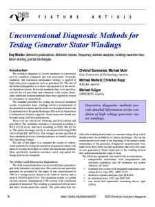
The main flow of the proposed layout-aware pseudofunctional testing methodology is illustrated in Fig. 1. We first identify true critical paths in the CUT using a commercial static timing analysis tool. Then, for each critical path, we parse the circuit layout to identify those cells that may induce power supply noise on it (Step 1). Next, we revise the method presented in [18] to identify illegal states that are related to these cells (Step 2). Then, by inserting functional constraints as virtual cells into the circuit, we are able to use a commercial ATPG tool to generate pseudo-functional test cubes for delay faults on critical paths (Step 3). Finally, we use several algorithms to fill X-bits in these test cubes to maximize PSN effects on critical paths without violating functional constraints (Step 4). The first three steps are introduced in the following subsections, while the last step (as the main contribution of this work) is detailed in Section 4. Step 1: Layout-aware PSNrelated cell identification
Netlist
Step 2: Functional constraints generation
Step 3: Relation extraction with circuit analysis
Layout
Step 4: Pseudo-functional test cube generation Functional constraints insertion
Timing analysis
Critical path
Path Delay Fault ATPG
Step 5: X-filling for maximizing power supply noise
Final pattern
Figure 1. Flowchart of Proposed Methodology.
3.1
Layout-Aware PSN-Related Cell Identification
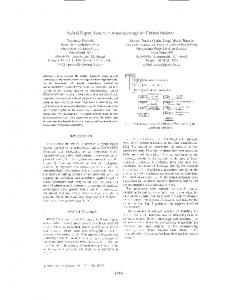
Power distribution network is typically designed with a hierarchical structure, which traverses several metal layers in the circuit. Fig. 21 depicts a typical power network structure, which involves three metal layers (M1, M4, and M5 from bottom up). The power wires on different metal layers are linked together through vias and eventually connected to the power pads at the uppermost layer. The devices are arranged below M1 layer in rows, and obtain power supply from power wires on M1 layer. It can be easily observed that, for a particular logic cell, it needs to compete for power supply with its neighboring cells. For a critical path under test, we denote those on-path logic cells and those cells that induce power supply noise on them as victim cells and aggressor cells, respectively. Generally speaking, for each victim cell, its aggressor cells can be restricted to a rectangle area that is within a few of its neighboring rows and a certain range along each row [7]. We 1 The
ground network is with similar structure and is not shown in Fig. 2.
M4
M4
M1
M1 M5 M1 SC
SC
SC
SC
SC
SC
SC
SC
SC
SC
the virtual output to be logic ‘0’, the generated test cube automatically avoids this illegal state. A commercial ATPG tool is then utilized to generate test cubes for targeted critical paths with the modified netlist and pre-set values on virtual outputs. After this step, for each targeted critical path, we have a test cube that does not contain any illegal states.
SC
M1
FF1 SC
SC
SC
Illegal State: FF1 FF2 FF3
Figure 2. An Example Power Distribution Network. therefore define a so-called E f f ectiveRange as a pre-defined maximum distance between the aggressor cells and the victim cells, and we parse the circuit layout DEF file to locate the aggressor cells.
3.2
1
Pseudo-Functional Path Delay Fault Test Cube Generation
In this step, we generate pseudo-functional test cubes for path delay faults (PDFs) on targeted critical paths, by constraining the ATPG engine to take the logically-relevant functional constraints of each path into consideration. Note that, it is not necessary to consider those physically-relevant functional constraints because only those scan cells that are logically related to the path delay fault will be assigned with specified values in the generated test cubes. To let ATPG engine automatically satisfy functional constraints during test generation, we insert virtual cells into the original circuit to represent them. An example is shown in Fig. 3, wherein illegal state “110” for “FF1 FF2 FF3” is represented in such manner that the associated virtual output is logic ‘1’ when this illegal state exists in the generated test cube. In other words, during the ATPG process, by assigning
1
FF2
Virtual Output
0 FF3
Figure 3. Example of Virtual Cell Insertion.
4
Pseudo-Functional X-Filling with Maximum PSN Effects on Critical Paths
Functional Constraint Generation
After obtaining all the logic cells that have impact on the delay of targeted critical paths (including both aggressor cells and victim cells, defined as relevant cells), we revise the method presented in [18] to generate functional constraints (i.e., illegal states in the circuit). Different from [18] that tries to extract illegal states of the entire circuit (and hence is time-consuming for large industrial circuits), we try to generate only those functional constraints that are relevant for critical path delays. In order to do so, we first conduct circuit structural analysis to identify those scan flip-flops that drive relevant cells in at-speed delay testing. This can be simply obtained by propagating the fan-out cone of each scan cell for two time-frames. We then make use of the technique in [18] to acquire all the relevant functional constraints for critical paths. Note that, for a critical path, its relevant functional constraints can be divided into two groups: one is logicallyrelevant functional constraints that are directly related to the on-path victim cells and the rest is physically-relevant functional constraints that are related to the aggressor cells to the path under test.
3.3
Virtual Cells
SC
With test cube generated for each critical path, our objective in this step is to fill the X-bits to maximize on-path PSN effects while still satisfying the path’s relevant functional constraints.
4.1
The Impact of X-Bits on PSN Effects
As filling one X-bit may affect the transitions of many aggressor cells for a critical path, it is essential to have an effective metrics to evaluate the impact of X-bits on the PSN effects of the targeted path delay fault. Before introducing our evaluation metrics, let us discuss the impact of different aggressors’ transitions on the PSN effects of a particular on-path victim cell first. It is obvious that the closer an aggressor is to a victim cell, the higher PSN it induces on it. We hence introduce a socalled PSN effect weight (PEW) for each aggressor to reflect this phenomenon, PEW = 1 − |Xagg − Xvic |/E f f ectiveRange
(1)
where Xagg and Xvic denote the row-coordinate of the aggressor and the victim, respectively. As pointed out in [7], the transition type of aggressor cells (e.g., rising or falling) also plays an important role for PSN effects on a victim cell. Consider an on-path victim cell in Fig. 4, to maximize power supply noise on it, for those aggressor cells that are in the same row, they are desired to have the same transition type as the victim cell; for those aggressor cells that are in different row but share a common power wire with it, they are desired to have a rising transition; while for the remaining aggressor cells that are in different row but share a common ground wire with it, they are desired to have a falling transition. It is obvious that the actual transition type of aggressor cells are constrained by the functionality of circuit and they are uncertain before filling all the X-bits in test cubes. Therefore, we define a probability-based transition PSN metric (PTPM) to evaluate the impact of X-bits on the PSN of targeted path from transitions of relevant gates as: PT PM =
n
m
∑ ∑ (T↓ × P(i, j) (↓) + T↑ × P(i, j) (↑)) × PEW(i, j)
i=1 j=1
(2)
Required Transition Type
Cell on the Path (Victim)
bits are handled first to satisfy functional constraints (detailed in Section 4.4).
Ground
Rise
Initial Test Cube 1:
Power
0
Same Fall
0
Power Cells in PSN-Related Region (Aggressors)
0
wherein n is the number of victim cells on the targeted path, m is the number of aggressors for each victim, P(i, j) (↓ / ↑) is the probability of jth aggressor, corresponding to ith victim, to have falling/rising transition, and PEW j is the PSN effect weight. To maximize PSN, when the falling transition is desired, we have T↓ = 1 and T↑ = 0, when the rising transition is desired, we have T↑ = 1 and T↓ = 0. It is also worth noting that, P(i, j) (↓ / ↑) is calculated by probability-based simulation of the circuit for two time frames, assuming the probabilities of X-bits in the first timeframe to be logic value ‘1’/‘0’ as 0.5.
The Impact of Functional Constraints on X-Filling
During X-filling, to satisfy functional constraints, the Xbits in the test cube cannot be filled freely all the time. As the example shown in Fig. 5, all the X-bits in the initial test cube can be filled freely at the beginning. However, after some of them are filled, in order not to violate the relevant illegal state, the last bit should be implied as ‘1’ 2 . Note that, the newly implied bit may result in the similar situation and other X-bits may further be implied. Hence, the X-implication should be conducted iteratively until no more X-bits can be implied by functional constraints. Initial Test Cube:
0
X X
X
After X-filling:
0
1
Illegal State:
0
X
0
1
0
0
X-implication:
0
1
0
0
X
1
0
X
0
0 X-implication to break illegal state 2:
X-implication to break illegal state 1:
Figure 4. Required Transitions to Maximize PSN Effects.
4.2
X X X
After X-filling:
Ground
1
1
0
1
0
0
0
1
Illegal State 1:
0
1
0
0
0
0
0
Illegal State 2:
1
0
0
0
Figure 6. Example for Conflict Bit.
4.3
Proposed X-Filling Algorithm
Based on above discussions, we present a bit-by-bit Xfilling procedure in this section, in which we fill the conflict X-bits first, followed by those non-conflict X-bits. 4.3.1 X-Filling Order In a bit-by-bit X-filling process, the filling order has a significant impact for the filling results [3]. While it is possible to temporarily fill every X-bit and calculate its PSN effect according to Eq. 2 to order these X-bits, the extensive use of circuit simulation inevitably leads to high computational complexity. To address the above issue, we implement a circuit analysis procedure to calculate the so-called filling impact (FI) of an X-bit and we use this value to order X-bits during the filling process. We start by initializing the FI for the scan cell with X-bit to be 1, and then propagate it through its logic cone for two timeframes to reach the aggressor cells that are driven by this scan cell. Every time a gate is passed, the possibility for the impact of this scan cell to pass through the gate is likely to be reduced by the other inputs. To estimate such weakening effect, we define a series of weakening parameters (WP) calculated by the following equations for various types of gates, in which n is the number of inputs to the gate and Pi (0/1) is the probability of the logic values on input i of the gate. W Pand/nand = W Por/nor =
n−1
∏ Pi (1)
(3)
i=1 n−1
∏ Pi (0)
(4)
i=1
Figure 5. Example for X-Implication.
W Pnot/xor/xnor = 1
Using X-implication only, however, cannot guarantee all functional constraint satisfied. There is one type of X-bits that appears in more than one illegal states and the corresponding values are ‘1’ in some states and ‘0’ in others (referred as “conflict X-bit”), as the example shown in Fig. 6. If these bits are not handled first, during X-filling, we may run into a situation that one conflict bit (as indicated in Fig. 6) need to be implied with opposite values to satisfy different functional constraints. To tackle this problem, we first analyze relevant illegal states for each targeted path and we divide X-bits into conflict X-bits and non-conflict X-bits. During the filling process, conflict X-
The idea behind the above definitions is that all the inputs except for the affected one should be set as non-controlling value (e.g., ‘1’ for ‘and’ gate) to propagate this effect. Hence, after the FI passes through a gate, it is weaken as FIout = FIin × W P. Then the filling impact for an X-bit (FIx ) is defined as the following equation to include both the PSN effect weight PEW and FI of every aggressor cell i.
2 This
process is referred to X-implication in the rest of this paper.
FIx = ∑(FIi × PEWi )
(5)
(6)
i
For each targeted path, the above calculation for the filling impact of X-bits is computed once only and used to determine the filling order, which is computationally-efficient.
Figure 7. Procedure for Conflict X-Bit Filling. For the remaining non-conflict X-bits, as X-implication is sufficient to satisfy functional constraints, these X-bits are simply filled bit-by-bit with their filling impact order. For each X-bit, similarly, we conduct probability-based simulations to evaluate their PSN effects, by assigning the to-be-filled X-bit to be ‘1’ and ‘0’, respectively, and we fill the X-bit as ‘0’ if PT PM(0) > PT PM(1); ‘1’ otherwise. X-implication is then conducted immediately to guarantee related functional constraints satisfied.
5
Experimental Results
To evaluate the effectiveness of the proposed method, we conduct experiments on two large ISCAS’89 benchmark circuits, s38417 and s38584. We synthesize and layout these circuits using a 0.13µm CMOS technology with Vcc = 1.08V . In our experiments, we apply the proposed technique on 10
5.35 Random Proposed
5.3
Path Delay (ns)
Algorithm for Filling Conflict X-bits 1 Function DFS(Current pattern P ) 2 If a valid solution has been found 3 return 4 If all conflict bits are filled 5 Declare that the valid solution has been found 6 return 7 Find out the first conflict X-bit i in pattern P 8 PT PM(0)=SIMULATION(i,0), PT PM(1)=SIMULATION(i,1) 9 If PT PM(0) > PT PM(1) 10 A ← 0 //Attempt to fill the ith bit with 0 first 11 else 12 A ← 1 //Attempt to fill the ith bit with 1 first 13 Fill the ith bit with A, achieving new pattern P � 14 P �� ←X-IMPLICATION(P � ) 15 If P �� does not have constraint violation 16 DFS(P �� ) ¯ achieving new pattern P � 17 Fill the ith bit with A, �� 18 P ←X-IMPLICATION(P � ) 19 If P �� does not have constraint violation 20 DFS(P �� )
longest testable paths in these circuits. For each path, after generating test patterns with the proposed method, we use a commercial IR-drop analysis tool to obtain the voltage of each cell on this path, and then we feedback these values to the static timing analysis tool to acquire the path delay under power supply noise effects. Firstly, let us compare the proposed method with the one that randomly fills X-bits in test cubes. As presented in Fig. 8, the bar chart describes the delay values of Path 1 in s38417 by filling the corresponding test cube with 10 random values, while the line indicates the path delay by proposed method. As shown in the figure, without considering PSN effects, among the ten random filled patterns, the first one may lead to overtesting of the circuit, while other seven may result in “test escape”. There are also two patterns having similar delay with the one filled using the proposed method. This is just a coincidence because all the ten random-filled patterns violate some functional constraints.
5.25
5.2
5.15
5.1
5.05
5
1
2
3
4
5
6
7
8
9
10
Figure 8. Comparison of Path 1 in s38417 between Random-Fill and Proposed Method. Next, we compare the proposed method with the one that randomly fills X-bits in test cubes without violating functional constraints, as shown in Fig. 9, targeting Path 1 in s38417 again. The bar chart describes 10 delay values by pseudofunctional random filling, while the line indicates the delay by proposed method. It can be observed that pseudo-functional patterns without considering maximizing PSN effects on the target path can introduce up to 7.9% less delay than the proposed method, which justifies the necessity of the proposed layout-aware pseudo-functional testing technique. 5.4 PF Random Proposed 5.3
Path Delay (ns)
4.3.2 X-Filling Procedure As discussed earlier, we need to fill those conflict X-bits first to avoid the ‘unsolvable’ situation as shown in Fig. 6. To guarantee the filling results have no functional constraint violations, we use a depth first search method with filling impactguided priority to find a valid solution. As shown in Fig. 7, before a conflict X-bit is filled, two probability-based simulations are conducted to evaluate their PSN effects using Eq. 2, by assigning the current X-bit to be ‘1’ and ‘0’, respectively (Line 8). We then fill the X-bit to be ‘0’ if the evaluation metric PT PM(0) > PT PM(1); ‘1’ otherwise (Line 9 to 12). The X-implication is conducted afterwards (Line 14). next, we check whether any functional constraint is violated. If not, we temporarily accept the filling result and continue the DFS procedure to find a valid X-filling solution on the remaining conflict X-bits according to the order. Otherwise, we try to fill the opposite logic value of current X-bit and call the same DFS procedure (Line 17 to 20). The whole process terminates when all conflict X-bits are filled without constraint violation (Line 4 to 6).
5.2
5.1
5
4.9
4.8
1
2
3
4
5
6
7
8
9
10
Figure 9. Comparison of Path 1 in s38417 between Pseudo-Functional Random-Fill and Proposed Method.
Path ID 1 2 3 4 5 6 7 8 9 10 Ave.
Pre. Fill 4.41 4.43 4.36 4.36 4.35 4.41 4.33 4.40 4.38 4.38 4.38
Max Fill 5.36 5.36 5.32 5.33 5.32 5.36 5.32 5.33 5.32 5.33 5.34
Proposed 5.29 5.29 5.26 5.26 5.31 5.29 5.24 5.27 5.26 5.27 5.27
Time (s) 36.2 35.9 36.3 36.3 36.1 36.5 35.8 36.0 35.8 35.9
Table 1. Comparison of Critical Path Delay (ns) in benchmark s38417. Finally, we compare the proposed method with two PSNaware X-filling method, Preferred Fill [10] and Max Fill, as shown in Table 1 and 2. In Preferred Fill, X-bits are filled to reduce scan capture power as much as possible and hence implicitly decrease PSN effects on critical paths [10]. The results (see Column “Pre. Fill”) show that this method is likely to introduce serious test escape problem, since it results in 16.9% and 15.8% less delay on average when compared that of patterns filled with the proposed method. Max Fill, on the other hand, is a greedy X-filling heuristic to maximize PSN effects without considering functional constraints, which fills all Xbits as non-conflict X-bits without conducting X-implication. The results (see Column “Max Fill”) show that the generated non-functional patterns in Max Fill leads to longer path delays than the proposed method (in the range of 1-4%), which may cause test overkill problem. Note that, the above difference is not as significant as the industrial study reported in [11] (test patterns can induce up to 20% longer delay than any functional pattern), we attribute it to the fact that our experiments are conducted with 0.13µm technology with relatively high supply voltage. In terms of computational time, the proposed method requires tens of seconds to process each critical path delay test cube on a 2.13GHz PC with 2GB RAM. Generally speaking, the relevant X-bits for critical paths in a circuit is within a range regardless of the circuit size. Therefore, we believe the proposed method is a scalable solution even for large industrial circuits.
6
Conclusion
In this paper, we propose novel layout-aware pseudofunctional testing techniques to exercise the worst-case timing of critical paths in functional mode, which facilitates to concurrently reduce test escapes and test overkills. Experimental results on large ISCAS’89 benchmark circuits demonstrate the benefits of the proposed methodology over prior works.
7
Acknowledgements
This work was supported in part by the General Research Fund CUHK417406, CUHK417807, and CUHK418708 from Hong Kong SAR Research Grants Council (RGC), in part by National Science Foundation of China (NSFC) under grant No. 60876029, and in part by a grant N CUHK417/08 from the NSFC/RGC Joint Research Scheme.
Path ID 1 2 3 4 5 6 7 8 9 10 Ave.
Pre. Fill 4.53 4.38 4.26 4.07 3.92 3.75 3.63 3.44 3.41 3.46 3.89
Max Fill 5.66 5.52 5.31 5.13 4.89 4.74 4.56 4.32 4.25 4.27 4.87
Proposed 5.57 5.37 5.21 4.96 4.77 4.57 4.44 4.17 4.16 4.11 4.73
Time (s) 34.0 33.8 33.6 33.9 33.9 34.1 34.1 33.4 33.8 32.9
Table 2. Comparison of Critical Path Delay (ns) in benchmark s38584.
References [1] Moderator: K. Butler, Organizer: N. Mukherjee. Power-Aware DFT - Do We Really Need it? Panel, International Test Conference, 2008. [2] A. Krstic, Y.-M. Jiang, and K. T. Cheng. Pattern Generation for Delay Testing and Dynamic Timing Analysis Considering Power-Supply Noise Effects. IEEE Transactions on Computer-Aided Design, 20(3):416–425, March 2001. [3] J. Li, Q. Xu, Y. Hu, and X. Li. iFill: An Impact-Oriented X-Filling Method for Shift- and Capture-Power Reduction in At-Speed Scan-Based Testing. In Proceedings IEEE/ACM Design, Automation, and Test in Europe (DATE), pages 1184–1189, 2008. [4] Y.-C. Lin, F. Lu, and K. Cheng. Pseudofunctional Testing. IEEE Transactions on Computer-Aided Design, 25(8):1535–1546, August 2006. [5] J.-J. Liou, A. Krstic, Y.-M. Jiang, and K.-T. Cheng. Path Selection and Pattern Generation for Dynamic Timing Analysis Considering Power Supply Noise Effects. In Proceedings International Conference on Computer-Aided Design (ICCAD), page 493–497, 2000. [6] X. Liu and M. S. Hsiao. A Novel Transition Fault ATPG that Reduces Yield Loss. IEEE Design & Test of Computers, 22(6):576–584, Nov.-Dec. 2005. [7] J. Ma, J. Lee, and M. Tehranipoor. Layout-Aware Pattern Generation for Maximizing Supply Noise Effects on Critical Paths. In Proceedings IEEE VLSI Test Symposium (VTS), 2009. [8] P. Maxwell, I. Hartanto, and L. Bentz. Comparing Functional and Structural Tests. In Proceedings IEEE International Test Conference (ITC), pages 400–407, 2000. [9] S. Remersaro, X. Lin, S. M. Reddy, I. Pomeranz, and J. Rajski. Scan-Based Tests with Low Switching Activity. IEEE Design & Test of Computers, 24(3):268–275, May-June 2007. [10] S. Remersaro, X. Lin, Z. Zhang, S. Reddy, I. Pomeranz, and J. Rajski. Preferred Fill: A Scalable Method to Reduce Capture Power for Scan Based Designs. In Proceedings IEEE International Test Conference (ITC), 2006. [11] S. Sde-Paz and E. Salomon. Frequency and Power Correlation between At-Speed Scan and Functional Tests. In Proceedings IEEE International Test Conference (ITC), paper 13.3, 2008. [12] M. Syal, K. Chandrasekar, V. Vimjam, M. S. Hsiao, Y.-S. Chang, and S. Chakravarty. A Study of Implication Based Pseudo Functional Testing. In Proceedings IEEE International Test Conference (ITC), page paper 24.3, 2006. [13] C. Tirumurti, S. Kundu, S. Sur-Kolay, and Y.-S. Chang. A Modeling Approach for Addressing Power Supply Switching Noise Related Failures of Integrated Circuits. In Proceedings IEEE/ACM Design, Automation, and Test in Europe (DATE), pages 1078–1083, 2004. [14] J. Wang and D. M. Walker. Modeling Power Supply Noise in Delay Testing. IEEE Design & Test of Computers, 24(3):226–233, May-June 2007. [15] X. Wen, K. Miyase, T. Suzuki, S. Kajihara, Y. Ohsumi, and K. K. Saluja. CriticalPath-Aware X-Filling for Effective IR-Drop Reduction in At-Speed Scan Testing. In Proceedings ACM/IEEE Design Automation Conference (DAC), pages 527– 532, June 2007. [16] Q. Xu, D. Hu, and D. Xiang. Pattern-Directed Circuit Virtual Partitioning for Test Power Reduction. In Proceedings IEEE International Test Conference (ITC), paper 25.2, 2007. [17] F. Yuan and Q. Xu. SoC Test Architecture Design and Optimization Considering Power Supply Noise Effects. In Proceedings IEEE International Test Conference (ITC), paper 26.2, 2008. [18] F. Yuan and Q. Xu. On Systematic Illegal State Identification for PseudoFunctional Testing. In Proceedings ACM/IEEE Design Automation Conference (DAC), pages 702–707, 2009. [19] F. Yuan and Q. Xu. Compression-Aware Pseudo-Functional Testing. In Proceedings IEEE International Test Conference (ITC), paper 9.1, 2009. [20] Z. Zhang, S. Reddy, and I. Pomeranz. On Generate Pseudo-Functional Delay Fault Tests for Scan Designs. In Proceedings IEEE International Symposium on Defect and Fault Tolerance in VLSI Systems (DFT), pages 215–226, 2005. [21] S. Zhao and K. Roy. Estimation of Switching Noise on Power Supply Lines in Deep Sub-Micron CMOS Circuits. In Proceedings International Conference on VLSI Design, pages 168–173, 2000.