6.012 Lecture 2. Electronic Devices and Circuits - S2007. 1. Lecture 2.
Semiconductor Physics (I). Outline. • Intrinsic bond model : electrons and holes.
Lecture 2 Semiconductor Physics (I)
Outline • • • • •
Intrinsic bond model : electrons and holes Generation and recombination Intrinsic semiconductor Doping: Extrinsic semiconductor Charge Neutrality
Reading Assignment: Howe and Sodini; Chapter 2. Sect. 2.1-2.3
6.012 Lecture 2
Electronic Devices and Circuits - S2007
1
1. Silicon bond model: electrons and holes Si is Column IV of the periodic table: IIIA
IVA 5
B Al
IIB 30
31
VIA
6
C 13
VA
N 14
Si 32
8
7
O 16
15
P
S 33
34
Zn Ga Ge As Se 48
Cd
49
In
50
51
52
Sn Sb Te
• Electronic structure of silicon atom: – 10 core electrons (tightly bound) – 4 valence electrons (loosely bound, responsible for most of the chemical properties
• Other semiconductors: – Ge, C (diamond form) – GaAs, InP, InGaAs, InGaAsP, ZnSe, CdTe (on the average, 4 valence electrons per atom)
6.012 Lecture 2
Electronic Devices and Circuits - S2007
2
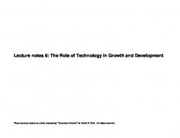
Silicon crystal structure
° 5.43 A ° 2.35A
3sp tetrahedral bond
• Diamond lattice: atoms tetrahedrally bonded by sharing valence electrons – covalent bonding
• Each atom shares 8 electrons – low energy situation
• Si atomic density : 5 x 1022 cm-3
6.012 Lecture 2
Electronic Devices and Circuits - S2007
3
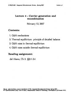
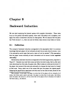
Simple “flattened” model of Si crystal
4 valence electrons (– 4 q), contributed by each ion
silicon ion (+ 4 q)
border of bulk silicon region
two electrons in bond
At 0K:
• All bonds are satisfied – ⇒ all valence electrons engaged in bonding
• No “free” electrons
6.012 Lecture 2
Electronic Devices and Circuits - S2007
4
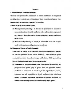
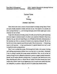
At finite temperature
–
+
border of bulk silicon region
mobile electron
incomplete bond (mobile hole)
• Finite thermal energy • Some bonds are broken • “free” electrons – Mobile negative charge, -1.6 x 10⁻¹⁹ C
• “free” holes – Mobile positive charge, +1.6 x 10⁻¹⁹ C Caution: picture is misleading! Electrons and holes in semiconductors are “fuzzier”: they span many atomic sites 6.012 Lecture 2
Electronic Devices and Circuits - S2007
5
A few definitions: • In 6.012, “electron’ means free electron • Not concerned with bonding electrons or core electrons • Define: – n ≡ (free) electron concentration [cm-3] – p ≡ hole concentration [cm-3]
6.012 Lecture 2
Electronic Devices and Circuits - S2007
6
2. Generation and Recombination GENERATION=break-up of covalent bond to form electron and hole pairs • Requires energy from thermal or optical sources (or external sources) • Generation rate: G = G(th) + Gopt + ....[cm −3 • s−1 ] • In general, atomic density >> n, p ⇒ G ≠ f(n,p)
– supply of breakable bonds virtually inexhaustible
RECOMBINATION=formation of covalent bond by bringing together electron and hole • Releases energy in thermal or optical form • Recombination rate: R = [cm −3 • s−1 ] • 1 recombination event requires 1 electron + 1 hole ⇒ R∝ n• p Generation and recombination most likely at surfaces where periodic crystalline structure is broken 6.012 Lecture 2
Electronic Devices and Circuits - S2007
7
3. Intrinsic semiconductor THERMAL EQUILIBRIUM Steady state + absence of external energy sources G o = f(T)
Generation rate in thermal equilibrium:
Recombination rate in thermal equilibrium: Ro ∝ no • po In thermal equilibrium: Every process and its inverse must be EQUAL
Go (T) = Ro ⇒ n o po = k oGo (T) n o po = n i2 (T)
Only function of T
n i ≡ intrinsic carrier concentration [cm −3 ] In Si at 300 K (“room temperature”): ni ≈ 1x1010 cm-3 In a sufficiently pure Si wafer at 300K (“intrinsic semiconductor):
no = po = ni ≈ 1 ×10
10
cm
−3
ni is a very strong function of temperature
T ↑⇒ ni ↑ 6.012 Lecture 2
Electronic Devices and Circuits - S2007
8
4. Doping Doping = engineered introduction of foreign atoms to modify semiconductor electrical properties A. DONORS: • Introduce electrons to semiconductors (but not holes) • For Si, group V elements with 5 valence electrons (As, P, Sb) IIIA
IVA 5
B Al
IIB 30
31
VIA
6
C 13
VA
N 14
Si
8
7
O 16
15
P
32
S 33
34
Zn Ga Ge As Se 48
Cd 6.012 Lecture 2
49
In
50
51
52
Sn Sb Te
Electronic Devices and Circuits - S2007
9
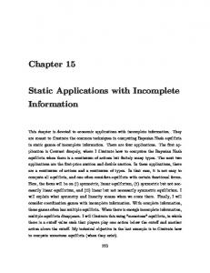
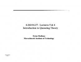
Doping: Donors Cont’d... • 4 electrons participate in bonding • 5th electron easy to release⇒ – at room temperature, each donor releases 1 electron that is available for conduction • Donor site become positively charged (fixed charge)
– As+
mobile electron
border of bulk silicon region
immobile ionized donor
Define: Nd ≡ donor concentration [cm-3] • If Nd > ni, doping controls carrier concentration – Extrinsic semiconductor⇒ n2 n0 = Nd
po =
i
Nd
Note: no >> po : n-type semiconductor Example: Nd=1017 cm-3 → no=1017 cm-3 , po=103 cm-3 In general:
Nd ≈ 1015 - 1020 cm-3
lg no lg po
no
ni
po
ni intrinsic
lg Nd extrinsic
• Electrons = majority carriers • Holes = minority carriers 6.012 Lecture 2
Electronic Devices and Circuits - S2007
11
Doping : Acceptors A. ACCEPTORS: • Introduce holes to semiconductors (but not electrons) • For Si, group III elements with 3 valence electrons (B) IIIA
IVA 5
B Al
IIB 30
31
VIA
6
C 13
VA
N 14
Si 32
8
7
O 16
15
P
S 33
34
Zn Ga Ge As Se 48
Cd
6.012 Lecture 2
49
In
50
51
52
Sn Sb Te
Electronic Devices and Circuits - S2007
12
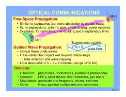
Doping: Acceptors Cont’d... • 3 electrons participate in bonding • 1 bonding site “unsatisfied” making it easy to “accept” neighboring bonding electron to complete all bonds⇒ – at room temperature, each acceptor “releases” 1 hole that is available for conduction
• Acceptor site become negatively charged (fixed charge)
B–
+
mobile hole and later trajectory
immobile negatively ionized acceptor
Define: Na ≡ acceptor concentration [cm-3] • If Na > ni, doping controls carrier conc. – Extrinsic semiconductor ⇒
po = Na
Note: po >> no : p-type semiconductor
2
ni no = Na
Example: Na=1017 cm-3 → po=1017 cm-3 , no=103 cm-3 Na ≈ 1015 - 1020 cm-3
In general: lg no lg po
po
ni
no
ni intrinsic
lg Na extrinsic
• Holes = majority carriers • Electrons = minority carriers 6.012 Lecture 2
Electronic Devices and Circuits - S2007
14
5. Charge Neutrality – As+
mobile electron
border of bulk silicon region
immobile ionized donor
• The semiconductor remains charge neutral even when it has been doped – ⇒ Overall charge neutrality must be satisfied
• In general:
ρ = q(po − no + Nd − Na )
Let us examine this for Nd = 1017 cm-3, Na = 0 We solved this in an earlier example: n 2i n o = Nd = 10 cm , p o = = 103 cm−3 Nd 17
Hence:
−3
ρ ≠ 0 !! What is wrong??
6.012 Lecture 2
Electronic Devices and Circuits - S2007
15
Charge Neutrality cont’d... Nothing wrong! We just made the approximation when we assumed that no = Nd We should really solve the following system of equations (for Na=0):
po − no + Nd = 0 n o po = n2i Solution and discussion tomorrow in recitation. Error in most practical circumstances too small to matter!
6.012 Lecture 2
Electronic Devices and Circuits - S2007
16
Summary Why are IC’s made out of Silicon? SILICON IS A SEMICONDUCTOR— a very special class of materials • Two types of “carriers” (mobile charge particles): – electrons and holes • Carrier concentrations can be controlled over many orders of magnitude by addition “dopants” – selected foreign atoms • Important Equations under Thermal Equilibrium conditions – Charge Neutrality – Law of Mass Action
po − no + N d − Na = 0 no po = ni2
6.012 Lecture 2
Electronic Devices and Circuits - S2007
17