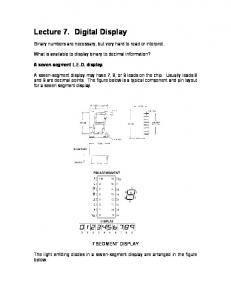
Conditional output box (oval shape). ▫ State box: containing register transfer
operations or activated output signals. 6-20. Basic Elements of ASM Chart (2/2).
Modeling Digital Systems with Verilog Prof. Chien-Nan Liu TEL: 03-4227151 ext:34534 Email:
[email protected] 6-1
Composition of Digital Systems
Most digital systems can be partitioned into two types of modules:
Datapath: perform data-processing operations between registers Controller: determine the sequence of those operations
6-2
1
Register Transfer Operations
The movement of the data stored in registers and the processing performed on the data are referred to as register transfer operations Ex: If (K1 = 1) then (R2 Å R1)
6-3
Multiplexer-Based Transfer
When a register receives data from two or more different sources at different times, a multiplexer can be used Ex: If (K1 = 1) then (R0 Å R1) else if (K2 = 1) then (R0 Å R2)
6-4
2
Bus-Based Transfer
Each register has its own multiplexers
May be too complex for large systems
Use shared transfer path instead
Often called a bus Can have only one source but multiple destinations at a time More hardware-efficient 6-5
Three-State Bus
A bus can be constructed with the three-state buffers Many three-state buffer outputs can be connected together
three-state register with bidirectional data line
Avoid the high-fanin OR in multiplexers Delay time and logic complexity can be reduced
The signals can travel in two directions on a three-state bus
EN=1: output, EN=0: input Simplify the interconnections 6-6
3
Disadv. of Three-State Bus
Bus connection problems
?
Bus floating problems
May reduce reliability One and only one active bus driver at a time Limited driving strength
Floating nets with ambiguous logic values Solution: bus keeper or pull up/down resistances
ATPG problem FPGA prototyping problem 6-7
Modeling Three-State Registers
To declare a bidirectional data port, inout type is used instead of input or output Ex: module TriReg(CLK, Rst, EN, Load, Data); input CLK, Rst, EN, Load; inout Data; reg int_data, Data;
separated to ensure correct circuits
always @(posedge CLK) begin if (Rst) int_data = 0; else if (Load) int_data = Data; end
register
always @(int_data or EN) begin if (EN) Data = int_data; else Data = 1`bz; three-state control end endmodule 6-8
4
HDL Modeling for Buses
To model the behavior of a three-state bus, tri type is used instead of wire
tri: has the same properties of wire but indicates more than one drivers may connect to it
Ex: module TriBus(CLK, Rst, E2, E1, E0, L2, L1, L0); input CLK, Rst, E2, E1, E0, L2, L1, L0; tri databus; TriReg R0(CLK, Rst, E0, L0, databus); TriReg R1(CLK, Rst, E1, L1, databus); TriReg R2(CLK, Rst, E2, L2, databus); endmodule
all connected together
6-9
Datapaths
A typical datapath often consists of:
Register file Arithmetic/logic unit (ALU) Shifter (may be implemented in ALU) Status signals that feedback to controller status bits 6-10
5
Arithmetic/Logic Unit ALU = Arithmetic Circuit + Logic Circuit
6-11
Arithmetic Circuit Eight arithmetic functions can be performed by setting the three control signals: S1, S0, Cin.
6-12
6
Logic Circuit
6-13
The Shifter
A bidirectional shift register can meet the basic requirement for the shift operations
One shift operation per clock cycle for shift registers
Shift left and shift right A faster method is often required
Combinational shifter can be used instead
S=00 : keep unchanged S=01 : shift right S=10 : shift left S=11 : undefined 6-14
7
Barrel Shifter
In some datapaths, the data must be shifted more than one bit position in a single clock cycle
Barrel shifter is used
A barrel shifter with 2n input and output lines requires 2n multiplexers and n selection inputs 6-15
Modeling the Barrel Shifter
Describe one by one case (select) 2`b00: Y = D; 2`b01: Y = {D[2:0], D[3]}; 2`b10: Y = {D[1:0], D[3:2]}; 2`b10: Y = {D[0], D[3:1]}; endcase
Incorrect description case (select) 2`b00: Y = D; 2`b01: Y = D