Change Impact Analysis of Crosscutting in Software Architectural Design Klaas van den Berg Software Engineering Group, University of Twente 7500 AE Enschede, the Netherlands
[email protected] Abstract. Software architectures should be amenable to changes in user requirements and implementation technology. The analysis of the impact of these changes can be based on traceability of architectural design elements. Design elements have dependencies with other software artifacts but also evolve in time. Crosscutting dependencies may have a strong influence on modifiability of software architectures. We present an impact analysis of crosscutting dependencies in architectural design. The analysis is supported by a matrix representation of dependencies. Keywords: Change impact analysis, dependency graph, dependency matrix, crosscutting, software evolution.
1
Introduction
Change management is a prerequisite for high-quality software development. Changes may be caused by changing user requirements and business goals or be induced by changes in implementation technologies. Software architectures must be designed such that they can evolve to cope with these changes. An analysis of the impact of such changes is necessary for cost effective software development [3]. The number of affected modules or elements is a response measure for the quality attribute modifiability in software architectural design [5]. Such analysis can be based on dependency traces between elements in the architectural design and other software artifacts. We will elaborate on traceability research in requirements engineering [15,25]. In case of crosscutting dependencies, the impact can be large. Crosscutting has been studied extensively in the context of Aspect Oriented Software Development (AOSD) [13]. In this paper, we present a framework for change impact analysis in case of crosscutting in the architectural design. The impact analysis is based on traceability of dependencies between elements in software artifacts. We propose a matrix representation of dependencies, together with formal definitions of specific cases of dependencies, such as tangling, scattering and crosscutting. We extend the approach of traceability to evolution of these elements. We define crosscutting dependencies between elements and show that crosscutting may have a large change impact.
The paper is structured as follows. In Section 2, we introduce definitions of traceability including the tracing of evolution of design elements. We show how trace data can be used in impact analysis. In Section 3, we introduce the definition of crosscutting and related concepts scattering and tangling. We describe how to represent and visualize crosscutting in matrices. In Section 4, we described the change impact analysis for trace dependencies between two levels and for multiple levels. Finally in Sections 5 and 6, we describe related work and present conclusions of the paper.
2
Tracing Evolution
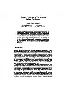
In this section, we give some background to traceability and change impact analysis to support software evolution. Traceability is defined as the degree to which a relationship can be established between two or more products of the development process, especially products having a predecessor-successor or master-subordinate relationship to one another [16]. In Gotel and Finkelstein [15], traceability is defined in the context of requirements engineering, and a distinction is made between pre-requirements specification traceability (forward to requirements and backward from requirements) and post-requirements specification traceability (forward from requirements and backward to requirements). Moreover, one may distinguish inter-level trace dependencies (sometimes called horizontal traceability) and intra-level trace dependencies (or vertical traceability) [1].
Figure 1. Traceability in Software Development
In Figure 1, several types of traceability are shown. (Remark: We prefer not to use the terms vertical and horizontal because they are dependent on the layout. In Figure 1, the inter-level relationships are represented as vertical arrows.) Architectural design elements are traced backwards to requirements and forward to elements in the detailed design. Elements at the architectural design may have intra-level dependency relations, and may evolve to a new configuration of architectural elements. In Ramesh and Jarke [25], a meta-model for requirements traceability is discussed, together with instances of traceability links. There are traceability links between artifacts (such as requirements and architectural design elements) and links representing the evolution and/or incremental development of these artifacts. Impact analysis is the activity of identifying what to modify to accomplish a change, or identifying the potential consequences of a change [3]. Impact is usually related with maintenance effort. “Impact analysis is the evaluation of the many risks associated with the change, including estimates of effects on resources, effort, and schedule” [24 p.490]. Instead of an adaptive maintenance model (see Figure 2), we will focus on the identification which elements are involved in the change. This has to be captured in a change impact model. Eventually in a quality improvement model, the change impact analysis and maintenance effort have to be related in empirical validation studies. External Factors
Adaptive Maintenance Model
Software Artifacts and Software Process
Change Impact Model
Measurement Value
Quality Improvement Model
Measurement Value
Figure 2. Quantitative Software Improvement for Evolution AOSD aims at a proper separation of concerns in the software development process. “The distribution of the code for realizing a concern becomes especially critical as the requirements for that system evolve – a system maintainer must find and correctly update a variety of (likely poorly identified) situations.” [13, p. 2]. In this update effort, the maintainer has both to know what to change and what to preserve. In our case, it is not just the elements that have to be changed, but also the elements (and mappings) that have to be preserved (which requires the effort of understanding). This will be explained in Section 4.
3
Crosscutting in Design
The problem of crosscutting has been studied in AOSD. Crosscutting can occur at implementation level, but also in early phases of software development [13]. In previous papers [6,7,8], we generalized the concept of crosscutting by means of a crosscutting pattern (see Figure 3). We call this a pattern as in [14], because it is a recurring problem (obvious from Figure 1) for which we propose a conceptual framework for solutions. In this pattern, we have dependency relations between elements in the source and elements in the target. These dependency relations also provide traceability between the elements, as well as inter-level relations as intra-level relations. Intralevel relations denote coupling between elements at a certain level. There is extensive literature on different types of coupling and the trade-off between coupling and cohesion (e.g. [11]). Here, we focus on inter-level dependencies. We now summarize our definition of crosscutting.
Figure 3. Traceability Pattern for Crosscutting Our proposition is that crosscutting can only be defined in terms of 'one thing' with respect to 'another thing'. In other words, at least two domains (or two levels or two phases) are related with each other in some way. • A domain could refer for example to a concern model with concerns or to a design with architectural elements. • A level could refer for example to refinements in the Model Driven Architecture (e.g. CIM, PIM and PSM) [23]. • A phase could refer to any phase in the software development life cycle (e.g. requirements, design, and so on). We use here the general terms source and target (as in [23]) to denote two consecutive domains, phases or levels. We assume that elements in the source are related to elements in the target: there is a mapping between source and target elements. The mapping can be established manually or be automated in transformation rules. We may distinguish several cases of mappings between source and target. This can be represented in a dependency graph, as shown in Figure 4:
• • • •
Injection: a source element is related to a distinct target element (e.g. s2 to t2) Scattering: a source element is related to multiple target elements (e.g. s1 to t1, t3 and t4) Tangling: a target element is related to multiple source elements (e.g. s1 and s3 to t3) Crosscutting: a target element is involved both in scattering and tangling (e.g. t3; scattering of s1 to t1, t3 and t4, and tangling of s1 and s3 in t3) source
target
t1
s1
s2
t2
s3
t3
t4
Figure 4. Mapping between Elements at two Levels of Abstraction (s1, s2, s3 at source; t1, t2, t3 and t4 at target) We say that source element s1 crosscuts source element s3 with respect to the given mapping between source and target. According to our definition in [7], crosscutting occurs when in a mapping between source and target, a source element is mapped to two or more target elements and at least one of these target elements has a mapping from one other source element. Although crosscutting is defined as a relation between source elements (see Figure 3), the crosscutting relation depends on the mapping between source and target. Coupling is also defined as a relation between elements at source level; however this relation just depends on intra-level relationships. In broad sense, we may define crosscutting just as scattering and tangling [13]. Above, we defined crosscutting - in narrow sense - as a specific combination of tangling and scattering. 3.1
Matrix representation
In this section, we describe how crosscutting – as shown in the dependency graph can be represented in matrices. As starting point, the developer must establish a dependency matrix showing the mapping between source and target. From this matrix, we derive the crosscutting matrix, where we represent the crosscutting source elements. The relation between source elements and target elements can be represented in a matrix that we called dependency matrix. As described before, the mapping can have different types, such as usage and abstraction dependencies (e.g. realization, refinement and tracing [26]). A dependency matrix (source x target) represents the dependency relation between source elements and target elements (inter-level relationship). In the rows, we have the source elements, and in the columns, we have the target
elements. In this matrix, a cell with 1 denotes that the source element (in the row) is mapped to the target element (in the column). Reciprocally this means that the target element is related to the source element. Scattering and tangling can easily be visualized in this matrix (see the examples below). We define an auxiliary concept crosscutpoint used in the context of dependency matrices, to denote a matrix cell involved in both tangling and scattering. If there is one or more crosscutpoints then we say we have crosscutting.
dependency matrix target t[1] t[2] t[3] s[1] 1 0 1 s[2] 0 1 0 s[3] 0 0 1 NT NT T
source
source
Table 1. Example Dependency Matrix and Crosscutting Matrix
crosscutting matrix source s[1] s[2] s[1] 0 0 s[2] 0 0 s[3] 0 0
t[4] 1 0 0 NT
S NS NS
s[3] 1 0 0
Crosscutting between source elements for a given mapping to target elements, as shown in a dependency matrix, can be represented in a crosscutting matrix. A crosscutting matrix (source x source) represents the crosscutting relation between source elements, for a given source to target mapping (represented in a dependency matrix). In the crosscutting matrix, a cell with 1 denotes that the source element in the row is crosscutting the source element in the column. A crosscutting matrix should not be confused with a coupling matrix. A coupling matrix shows coupling relations between elements at the same level (intra-level dependencies) [9]. In some sense, the coupling matrix is related to the design structure matrix [4]. However, a crosscutting matrix shows crosscutting relations between elements at one level with respect to a mapping onto elements at some other level (inter-level dependencies). We now give an example and use the dependency matrix and crosscutting matrix to visualize the definitions (S denotes a scattered source element - a grey row; NS denotes a non-scattered source element; T denotes a tangled target element - a grey column; NT denotes a non-tangled target element). The example is shown in Table 1, representing the mapping from Figure 4. In this example, we have one scattered source element s[1] and one tangled target element t[3]. Moreover there is one crosscutpoint at matrix cell [1,3] (dark grey cell). Applying our definition, we arrive to the crosscutting matrix. Source element s[1] is crosscutting s[3] (because s[1] is scattered over [t[1], t[3], t[4]] and s[3] is in the tangled one of these elements, namely t[3]). The reverse is not true: the crosscutting relation is not symmetric.
In [7], we show how to construct the crosscutting matrix from the dependency matrix using some matrix operations. For convenience, these formulas can be calculated by means of simple mathematic tools. By filling in the cells of the dependency matrix, the crosscutting matrix is calculated automatically. 3.2
Multiple levels of dependencies
Above, we only considered dependencies between two levels. Usually we encounter multiple levels as shown in Figure 1. In that case we have to take into account the transitivity of trace dependency relations. This can be accomplished through the cascading of the dependency pattern as described in [9]. The main concepts will be summarized here (see Figure 5 ). Assume we have two patterns: between domains A and B, and between domains B and C.
Figure 5. Cascading of Traceability Pattern The target of the first pattern serves as source in the second pattern. Then, the transitivity dependency relation rel for source A, intermediate level B and target C, and #B is the number of elements in B is defined as follows: ∃ k ∊ (1..#B): (A[i] rel B[k]) ∧ (B[k] rel C[m]) ⇒ (A[i] rel C[m])
We may support this analysis with a matrix analysis. We consider the three domains (or levels) A, B and C (see Table 2). Table 2. Forward and Backward Trace Dependencies for three levels
Domain A
Domain B
Domain C
Domain A Coupling (AxA) Backward Trace Dependency (AxB)T Backward Trace Dependency ((AxB)(BxC))T
Domain B Forward Trace Dependency (AxB) Coupling (BxB) Backward Trace Dependency (BxC)T
Domain C Forward Trace Dependency (AxB)(BxC) Forward Trace Dependency (BxC) Coupling (CxC)
Let the forward trace dependencies between level A and B be represented in the dependency matrix AxB, and the forward trace dependencies between level B and C in the dependency matrix BxC. The trace dependencies between level A and C based on the transitivity of dependencies can be obtained by means of the boolean matrix multiplication of the matrices AxB and BxC. The backward trace dependencies between level B and A can be obtained from the transposed dependency matrix (AxB)T. Similarly, we can obtain the other backward traceability relations. Trace dependencies between elements at the same level can be captured in the coupling matrix with adjacency relations. If coupling exists then the transitive closure has to be determined at each level, e.g. (AxA)*. The actual dependencies between two levels e.g. A and B, is then obtained through (AxA)*(AxB)(BxB)*. We will not consider coupling in this paper and focus on intralevel change impact analysis.
4
Change Impact of Crosscutting
In this section we describe the impact analysis of changes. We consider change impact in case of tangling, scattering and crosscutting, both for two-level dependencies and multiple-level dependencies. 4.1
Two-level impact analysis
Change impact in the traceability pattern is operationalized in terms of the elements involved in the change of a source element. The set of elements is called the impact set. We now show some examples of the change impact in case of a change in some source element. We consider the different cases of mappings between source and target. Injection: Scattering: Tangling: Crosscutting:
impact impact impact impact
s1 s2 s3 s5
=> => => =>
change (s1,t1) change ((s2,t2), (s2,t3)) change (s3,t4) + preserve (s4,t4) change ((s5,t5), (s5,t6)) + preserve ((s6,t6), (s7,t6))
Changing s1 (for injection) means that t1 need to be changed. Similarly, changing s2 (for scattering) means that t2 and t3 need to be changed. Changing s3 (for tangling) means that t4 need to be changed, however in this change, the dependency of s4 in t4 has to be preserved. Changing s5 for crosscutting means that t5 and t6 need to be changed, while preserving the dependency of s6 in t6, and of s7 onto t6.
s2 s1
t1
s4 s5
s3
t2
t4 t3
t5
s6
s7
t6
Figure 6. Examples of Change Impact As shown in these examples, the impact set consists of two subsets: impacted target elements that need to be changed (forward traceability from source to target), and impacted source elements that need to be preserved in this change of target elements (backward traceability from target to source). The severity of anticipated impact for injection is relatively weak, for scattering and tangling the anticipated impact is moderate, whereas for crosscutting the anticipated impact is strong. The severity of the actual impact in each case depends on the number of elements involved and eventually on the type of change required. Above, we only considered dependencies between two levels. Usually we encounter multiple levels as shown in Figure 1. In that case we have to take into account the transitivity of trace dependency relations. 4.2
Multi-level impact analysis
We extend our analysis to dependencies across multiple levels. Assume we change element v in the mapping (x,v). As shown in the previous section, there will be mappings that have to be changed and mappings that have to be preserved. The mappings involved in this change due to the change propagation can be obtained from the following recursive function: impact(x,v) = change(x,v) + (preserve(u,v) | u ← preds(v); x ≠ v) + (impact(v,w) | w ← succs(v))
where the function preds gives the predecessors of an element (adjacent elements in backward trace) and the function succs gives the successors of an element (adjacent elements in forward trace). The result of this function contains a list of mappings to be changed based on forward traceability, and a list of mappings to be preserved based on backward traceability.
a1
b1
c1
a2
b2
c2
a3
b3
c3
b4
c4
c5
Figure 7. Example with Trace Dependencies across three levels We show this in the following example (see Figure 7), in which we want to know the impact of changing element b2 in the mapping (a2,b2): impact(a2,b2) = change((a2,b2), (b2,c2), (b2,c3)) + preserve ((a1,b2), (b1,c2), (b3,c3))
There are 6 (unique) mappings involved in this change. There are 3 mappings to be changed and 3 mappings to be preserved. The impact of changing element a2 can be obtained in the same way: impact(a2,a2) = change((a2,a2),(a2,b2),(b2,c2),(b2,c3),(a2,b3),(b3,c3),(b3,c4)) + preserve ((a1,b2),(b1,c2),(b3,c3),(a3,b3),(b2,c3),(b4,c4))
In this example, the two mappings (b2,c3) and (b3,c3) have to be changed and at the same time to be preserved. Here, a strategy is required to resolve this conflict. Such a conflict only occurs in case of a combination of scattering at one level and tangling in a subsequent level, resulting in multiple paths from (initial) source to (final) target elements. Table 3. Results of Change Impact for example in Figure 7 mappings impact(a2,b2) impact(a2,a2)
changed 3 7
preserved 3 6
involved 6 11
conflicts 0 2
The results of these two examples are summarized in the following Table 3, where: #conflicts = #changed + #preserved - #involved
We may support this analysis with a matrix analysis. The example of Figure 7 can be represented in a dependency matrix (see Table 4). We have three levels A, B and C with elements (a1,a2,a3}, {b1,b2,b3,b4} and {c1,c2,c3,c4,c5}. For the impact (a2,a2) we shaded the cells of dependencies that have to be changed or preserved. There is one path from a2 to c2 as shown in cell (a2,c2), and there are two paths from a2 to c3 as shown in cell (a2,c3) indicating that there is a conflict. The dark grey cells represent the conflicting mappings (both to be changed and preserved).
Table 4. Dependency Matrix for Figure 7 with Change Impact (a2,a2) Gray cell: change or preserve. Dark cell: change and preserve a1
a2
a3
b1
b2
a1 a2
b3
b4
c1
c2
c3
c4
c5
1
0
0
1
1
0
0
1
2
1
0
0
0
1
0
0
1
1
0
0
1
2
1
0
a3
0
0
1
0
0
1
1
0
0
1
2
1
b1
1
0
0
1
0
0
0
1
1
0
0
0
b2
1
1
0
0
1
0
0
0
1
1
0
0
b3
0
1
1
0
0
1
0
0
0
1
1
0
b4
0
0
1
0
0
0
1
0
0
0
1
1
c1 c2 c3 c4
1
0
0
1
0
0
0
1
0
0
0
0
2
1
0
1
1
0
0
0
1
0
0
0
1
2
1
0
1
1
0
0
0
1
0
0
0
1
2
0
0
1
1
0
0
0
1
0
c5
0
0
1
0
0
0
1
0
0
0
0
1
The recursive nature of the impact function can be seen from going from one dependency matrix to the dependency matrix at the next level. The forward traceability is provided in the rows, whereas the backward traceability is provided in the columns. 4.3
Example
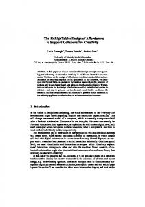
In this section, we show a small - and trivial - example with elements at three levels: requirements, architectural design and implementation. The system is a calculator with the following requirements: R1. Calculate The system shall calculate the addition and subtraction of real and integer numbers. R2. Feedback The system shall provide feedback on input errors. We selected the Model-View-Controller pattern for the architectural design, e.g. represented in three UML-classes. In the implementation in Java, it is decided (e.g. for performance reasons) to have two classes, one class Storage.java with the storage of numbers and one class Calculate.java with conversion of the input to numbers and the calculations. The three levels are shown in Figure 8 with the dependencies between the elements at each level.
R1: Calculate
Requirements
Design (UML classes)
Implementation (Java classes)
Model
R2: Feedback
Controller
Storage.java
View
Calculate.java
Figure 8. Calculator Example with Trace Dependencies between three levels Assume we want to change requirement R1 and add a new operation to the system (e.g. multiplication of numbers). The feedback requirement R2 is not changed. The impact of changing R1 is that we have to change the operators and attributes in the UML classes Model, View, and Controller. There are conflicts, because we have a combination of scattering and tangling, resulting in two paths from requirement R1 to both implementation classes. The severity of the conflicts depends on how strong the MVC-functionalities are coupled in the implementation classes.
5
Related Work
Several authors use matrices (design structure matrices, DSM) to analyze modularity in software design [4]. Lopes and Bajracharya [19] describe a method with clustering and partitioning of the design structure matrix for improving modularity of objectoriented designs. The design structure matrices represent intra-level dependencies (as coupling matrices) and do not address the inter-level dependencies as in the dependency matrices used for the analysis of crosscutting. Our definition of crosscutting is similar to the definition provided by Masuhara & Kiczales [22]. However, our definition is less restrictive and not symmetric as discussed in [7]. In project management, an extension to design structure matrices is proposed by Danilovic & Sandkull [10]. In so-called domain mapping matrices (DMM), they capture the dynamics of product development. In their terminology, the traditional DSMs support intra-domain analysis, whereas the DMMs support inter-domain analysis. The purpose of our dependency matrix is similar to these domain mapping matrices. Maletec et al. [21] describe an XML based approach to support the evolution of traceability links between models. Their traceability graph is similar to our dependency graph. However, they do not discuss change impact analysis. Luqi [20] uses graphs and sets to represent changes. Ajila [1] explicitly defines elements and relations between elements to be traced with intra-level and inter-level dependencies. Impact analysis based on transitive closures of call graphs is discussed in Law [17]. We used the transitive closure for dependency relations between elements at the same level (intra-level dependencies or coupling).
Similar to our approach, Lindvall et al [18] show tracing across phases again with intra-level and inter-level dependencies. They also discuss an impact analysis based on traceability data of an object-oriented system. However, they do not support their analysis with a formal graph or matrix model. Change impact analysis for software architectures has been studied by Zhao et al. [27]. They use a formal architectural description language to specify and graphs to represent the architectures. They restrict their analysis to the architectural level and not across multiple levels.
6
Conclusion
In this paper, we proposed a framework for the change impact analysis of software artifacts across several phases of software development and in the evolution of these artifacts. We defined a traceability pattern and defined specific cases of trace dependencies, i.e. tangling, scattering and crosscutting. Architectural design elements are related on one hand to requirements and elements in the detailed design, on the other hand they have trace dependencies in the evolution of the architecture. We analyzed the changed impact in case of tangling, scattering and crosscutting. We applied this analysis to two-level dependencies and to multiple-level dependencies. We used a matrix representation for the intra-level and inter-level dependencies. The change impact consists of mappings that need to be changed and mappings that need to be preserved. In specific cases, we found conflicts in the change propagation requiring at the same time change of the mapping and preservation of the mapping. These situations deserve special attention in software evolution and a strategy for the implementation of changes. The framework has to be validated in empirical case studies. We focused on the analysis of change impact based on trace dependencies. The derivation of dependencies and its analysis should be supported by tools in order to scale to industrial projects. Acknowledgments. This work has been carried out in conjunction with the AOSDEurope Project IST-2-004349-NoE [2] and of the ESI Project Darwin [12]. Pim van den Broek made valuable comments on an earlier version of this paper.
References 1.
Ajila, S. (1995). Software maintenance: An approach to impact analysis of object change. Software - Practice and Experience, 25 (10), 1155-1181
2.
AOSD-Europe (2005). AOSD Ontology 1.0 - Public Ontology of Aspect-Orientation. Retrieved May, 2005, from http://www.aosd-europe.net/documents/d9Ont.pdf
3.
Arnold, R. S. & Bohner, S. A. (1993). Impact analysis - towards a framework for comparison. Paper presented at the Conference on Software Maintenance
4.
Baldwin, C.Y. & Clark, K.B. (2000). Design Rules vol I, The Power of Modularity. MIT Press
5.
Bass, L., Clements, P. & Kazman, R. (2003). Software architecture in practice (2nd ed.). Boston: Addison-Wesley
6.
Berg, K. van den & Conejero, J. (2005a), A Conceptual Formalization of Crosscutting in AOSD. In Iberian Workshop on Aspect Oriented Software Development, Technical Report TR-24/05 University of Extremadura, 46-52. Granada, Spain
7.
Berg, K. van den & Conejero, J. (2005). Disentangling crosscutting in AOSD: a conceptual framework. In Second Edition of European Interactive Workshop on Aspects in Software, Brussels, Belgium
8.
Berg, K. van den, Conejero, J. M. & Hernández, J. (2006). Identification of crosscutting in software design. In AOM2006, 8th International Workshop on Aspect-Oriented Modeling, Bonn, Germany
9.
Berg, K. van den, Conejero, J. M., & Hernández, J. (2006b). Analysis of crosscutting across software development phases based on traceability. In Early Aspects at ICSE2006: Workshop in Aspect-Oriented Requirements Engineering and Architecture Design, Shanghai
10. Danilovic, M., Sandkull B. (2005). The use of dependence structure matrix and domain mapping matrix in managing uncertainty in multiple project situations. International Journal of Project Management 23 (3) 193-203 11. Darcy, D.P., Kemerer, C.F., Slaughter, S.A. & Tomayko, J.E. (2005). The structural complexity of software: an experimental test. IEEE Transactions on Software Engineering, 31 (11) 982- 995 12. Darwin (2005). Designing Highly Evolvable System Architectures. Retrieved March 13, 2006 from http://www.esi.nl/site/projects/darwin.html 13. Filman, R., Elrad, T., Clarke, S. & Aksit, M. (2004). Aspect-oriented software development: Addison-Wesley 14. Gamma, E., Helm, R., Johnson, R. & Vlissides, J. (1995). Design patterns. Elements of reusable object-oriented software. Addison-Wesley 15. Gotel, O. & Finkelstein, A.(1994). An Analysis of the Requirements Traceability Problem, IEEE International Conference on Requirements Engineering, Los Alamitos, California: IEEE Computer Society Press, April 1994, 94-101 16. IEEE (1990). IEEE Standard Computer Dictionary: A Compilation of IEEE Standard Computer Glossaries. Institute of Electrical and Electronics Engineers, New York 17. Law, J., & Rothermel, G. (2003). Whole program path-based dynamic impact analysis. Paper presented at the International Conference on Software Engineering 18. Lindvall, M. & Sandahl, K. (1998). Traceability aspects of impact analysis in objectoriented systems. Software Maintenance: Research and Practice, 10, 37-57 19. Lopes, C.V. & Bajracharya, S.K. (2005). An analysis of modularity in aspect oriented design. In 4th International Conference on Aspect-Oriented Software Development. Chicago, Illinois 20. Luqi. (1990). A graph model for software evolution. Transactions on Software Engineering, 18 (8), 917-927
21. Maletec, J.I., Collard, M.L. & Simoes, B. (2005). An XML Based Approach to Support the Evolution of Model-to-Model Traceability Links. Proceedings of the 3rd international workshop on Traceability in emerging forms of software engineering TEFSE, California 22. Masuhara, H. & Kiczales, G. (2003). Modeling Crosscutting in Aspect-Oriented Mechanisms. In 17th European Conference on Object Oriented Programming. Darmstadt 23. MDA (2003). MDA Guide Version 1.0.1, document number omg/2003-06-01 24. Pfleeger, S. L. (2001). Software engineering. Theory and practice: Prentice-Hall 25. Ramesh, B. & Jarke, M. (2001). Toward a Reference Model for Requirements Traceability. IEEE Transactions on Software Engineering, 27, 1, 58-93 26. UML (2004). Unified Modeling Language 2.0 Superstructure Specification. Retrieved October, 2004 from http://www.omg.org/cgi-bin/doc?ptc/2004-10-02 27. Zhao, J., Yang, H., Xiang, L. & Xu, B. (2002). Change impact analysis to support architectural evolution. Journal of Software Maintenance and Evolution: Research and Practice, 14, 317-333