New Data Encoding Method with a Multi-Value Logic for Low Power Asynchronous Circuit Design Eun-Ju Choi1 , Je-Hoon Lee2 and Kyoung-Rok Cho1 1 Computer and Communication Lab. Chungbuk Nat’l Univ. 12, Gaeshin-Dong, Cheongju-City, Rep. of Korea 2 Dept. of EE, Univ. of S. California 3740, McClintock Ave., L.A., CA, USA 90089
[email protected],
[email protected],
[email protected]
Abstract This paper presents an asynchronous encoding scheme using a MVL(Multi-Value Logic). This scheme reduces not only the number of wires but also the switching activities. It is achieved by the two proposed data encoding methods, RT/NRT(Return to Ternary/ Non Return to Ternary) encoding and hybrid ternary one. Conventional ternary encoding makes all data lines to intermediate to generate completion signal. In RT/NRT encoding, however, data lines with transferring zero do not change to intermediate value in order to reduce the switching activities. In hybrid ternary encoding, it needs only two half-swing to transfer 2-bit data. Indeed, it only needs two lines. As the results, a RT/NRT encoding shows 25% reduction in the signal transition and it achieve power reduction about 27% comparing to the conventional ternary one. In addition, a hybrid ternary encoding achieves 23% energy reduction.
1. Introduction The design model in asynchronous circuit can be categorized into two models according to whether both wire and gate delays are known or not, bounded delay model and DI (DelayInsensitive) model. DI circuit doesn’t need to know the precise latency of each module and wiring delay. However, it requires a completion signal from getting the data encoding that indicates complete operation of each functional block. A lot of data encoding schemes are introduced to the DI circuit such as a dual-rail, 1-of-4, and ter-
nary encoding [1-5]. The data encoding scheme is related to the circuit performance in terms of logic size and switching activities. To improve these performances, we propose an asynchronous ternary logic with a MVL. The conventional ternary encoding uses the three logic levels. The logical high and the logical low correspond to the valid data ‘1’, and ‘0’, respectively. An intermediate value represents the invalid data, spacer, which is a communication time between the functional blocks. It does not completely meet the DI assumption for asynchronous operation. Thus, we propose the new data encoding schemes using a MVL that it completely meets the assumption for DI model. First, we propose a RT/NRT encoding based on the MVL logic which reduces the number of switching activities. There is no overhead switching to zero transition and reduces the number of transition during the data transferring. It can also contribute reduction of the power consumption. Second, we propose hybrid ternary encoding. This reduces both the number of signal transition and the circuit area. Consequently, RT/NRT encoding reduces 25% switching activities and hybrid ternary encoding saves 30% of the circuit area. The paper is organized as follows. Sect. 2 describes the data encodings for DI asynchronous circuit. Sect. 3 presents RT/NRT encoding and asynchronous pipeline architecture. Sect. 4 presents the hybrid ternary encoding and the circuit design. In Sect. 5, we verify the effectiveness of the proposed encodings and show the simulation results. Finally, we conclude in Section 6.
Proceedings of the 36th International Symposium on Multiple-Valued Logic (ISMVL’06) 0-7695-2532-6/06 $20.00 © 2006
IEEE
2. Delay model and encoding scheme DI asynchronous circuit has an assumption that the gate delay and wire delay is blinded to the circuit designer. Figure 1 shows a handshaking model for DI asynchronous circuit. Each module communicates with other modules on a promised handshaking protocol. Sender outputs valid data to the next combinational logic. If all outputs are valid, it transit Req signal to high. When the combinational logic completes the computation, it may output the valid data to the next receiver. Data encoding allows generating a completion signal to indicate that it finished the assigned work at the combinational logic. The completion signal will drive the next receiver as soon as outputs of a combinational logic are valid. When a receiver saves all data from a combinational logic, Ack signal transits to high. Thus the signal transition is Ackn oReqpoCompletionp. Here, n and p mean the signal goes high and low, respectively. When completion signal from the combinational logic is transited to low, the receiver knows handshaking is completed. Note that the completion signal can be generated by data encoding. But, bundled delay model needs the precise delay estimation for both gate and wire of the combinational logic. This is major difference between the asynchronous circuit with DI delay model and that with bounded delay model. There are many data encoding schemes such as a dual-rail, 1-of-4, and ternary data encoding as shown in Fig. 2 [2-6]. The circuit complexity and switching activities are depended on a data encoding scheme. For example, the dual-rail encoding requires two wires for carrying one bit data as shown in Fig. 2(a) [3]. 1-of-4 encoding also requires 2n wires and control signal Ack, but it saves the 50% switching activities comparing to the conventional dual-rail encoding [4]. The ternary only requires n-wires for transferring n-bit data and a control wire, Ack, for handshaking [5, 6]. In contrast, it uses the three logic levels. The logical high and the logical low represent the valid data ‘1’, and ‘0’, respectively. The logical intermediate value represents an invalid data, spacing time, for a hand shaking. It significantly increases switching activities during data transferring and operating, even though it can reduce the number of data lines.
Fig. 1. Handshaking model for DI model
Fig. 2. Various data encoding scheme We adopt the MVL to asynchronous data encoding. In this paper, we propose two types data encoding schemes using a MVL, RT/NRT encoding and hybrid ternary encoding. The proposed encodings effectively reduce data lines against the bundled asynchronous circuit. In RT/NRT encoding, data lines with transferring zero are not changed to intermediate value which reduces the switching activities. In hybrid ternary encoding, it operate the same as a conventional 1-of-4 one. The both proposed encodings has the same number of data-lines for bundled delay model.
3. RT/NRT ternary encoding The encoding scheme for DI asynchronous circuit is essential to identify validity of the data. To judge this validity, it used to additional logic and wire. Conventional ternary encoding does not need additional lines because it can represent invalid data using the intermediate value. In Fig. 1, the sender confirms the completion of data trans-
Proceedings of the 36th International Symposium on Multiple-Valued Logic (ISMVL’06) 0-7695-2532-6/06 $20.00 © 2006
IEEE
ferring after it gets Ack from the receiver. The sender outputs all outputs with intermediate values to indicate the outputs are not valid no longer. Because the receiver has latched all data from the sender, it does not need to transfer the valid data further. Though conventional ternary encoding reduces the number of data lines, it increases the number of switching activities comparing to the 1-of-4 encoding. However, it has a potential to reduce both data-lines and switching activities because of ternary logic. The proposed encoding uses three logical levels such as 0, 1, and intermediate value, VI like a conventional ternary one. VH represents the valid data ‘1’, VL represents the valid data‘0’ and VI represents the invalid data, spacer. The only difference is that all data-lines do not transit to intermediate value to indicate the invalid state. When the sender transfer the data, logical ‘1’ and it receives an acknowledge signal from the receiver, the data always transit logic value, VI to indicate the space. In contrast, when the sender transfer the logical ‘0’ and it receives an acknowledge signal from the receiver, the data always preserve to ‘0’ as shown in Fig. 3. But, the receiver can exactly identify when data becomes invalid. In the proposed RT/NRT encoding, we consider transferring data is an invalid when one of data-lines changes to intermediate value. Thus, it reduces the switching activities without violation of DI assumption.
Fig. 3. Comparison between conventional ternary and RT/NRT ternary encoding
Fig. 4. The handshaking model and timing diagram of RT/NRT ternary encoding scheme There is an exceptional condition when all of input data are all zeros because it is impossible to determine the validity of them. In this case, every data line transit logic level VI as a conventional ternary encoding. Figure 4 illustrates the 2-phase handshaking model and timing diagram is useful for the proposed ternary data encoding, in each pipeline stage, which connects two combinational blocks, A and B. Each of the combinational blocks communicates with the proposed ternary data after its operation. The output of Block A is validated by Rinn, which forces the latch to store the current output by activating Lt1, as shown in Fig. 4 (b). After the TVT logic outputs the data, the completion signals, Ain, returns to an initial state space. As shown in Fig. 4, the proposed ternary handshaking model needs the additional blocks such as
Proceedings of the 36th International Symposium on Multiple-Valued Logic (ISMVL’06) 0-7695-2532-6/06 $20.00 © 2006
IEEE
IVD, TVT and ZD logic. The circuits are shown in Fig. 5. IVD logic is responsible to detect the intermediate value, which identify whether the transferring data is valid or not. TVT logic allows to output logical high, logical low, and the intermediate value. If the all inputs are valid, the receiver identify the inputs are valid. In contrast, if there is one more intermediate value, the receiver asserts that the input data is invalid. Additionally, zero detector needs to detect all zero inputs which cause the only exceptional condition.
4. Hybrid ternary encoding Table1. Hybrid ternary encoding Input(D0D1) Hybrid Ternary Invalid ZZ 00 0Z 01 Z1 10 1Z 11 Z0 The switching rules of the hybrid ternary encoding are illustrated in Table 1. Input data is grouped 2-bit and encoded to hybrid ternary scheme. In Table 1, value ‘Z’ represents intermediate value, VI. If inputs become ‘ZZ’, this represents space and other case decided upon hybrid ternary scheme.
Fig. 6. Handshaking model and timing diagram Fig. 5. Condition Detector Logic
Figure 6 illustrates the 2-phase pipeline handshaking and timing diagram is useful for the proposed hybrid ternary encoding. In Fig. 6(b), the output of control block, LEN is made with grouped 2-bit input. If one of grouped 2-bit data becomes invalid, LEN is disabled and all block is not operated. Thus, this operation can reduce the switch-
Proceedings of the 36th International Symposium on Multiple-Valued Logic (ISMVL’06) 0-7695-2532-6/06 $20.00 © 2006
IEEE
ing activities. As shown in Fig. 7(a), the proposed hybrid ternary handshaking model uses a simple control block without zero detector and completion check block in conventional ternary. Fig. 7(a) is control block diagram and Fig. 7(b) is completion detector using dynamic CMOS. If the all inputs are valid, the receiver identify the inputs are valid. For example, if ‘D0, D1’ in Fig. 7(b) is ‘Z0’, det0 insists high. Thus, besides det0, if det1~detn in Fig. 7(a) become high, LEN is enabled and control logic enables Latch in Fig.8. In contrast, if there are two more intermediate values, that is, LEN is low; the receiver decides that the input data is invalid. Therefore all blocks are disabled. The proposed data encoding scheme makes each combinational block detects the completion signal for the handshaking at the end of the circuit operation. If output of latch D0_out is validated by rising LEN high, the latch forces to store the current output and to operate logic block in Fig. 8. After the latch saves the valid output of latch, data returns to an initial state, space.
, where CL is a load capacitance and fC is the frequency for switching. This means that the potential power saving of the ternary encoding scheme is about quarter. In addition, the proposed scheme certainly reduces the required data lines by half. Furthermore, the potential power saving of the proposed ternary encoding scheme over the conventional ternary encoding scheme is about 25% when the sender transfers the 8-bit data. But we have leakage current problem that is about 12% of total block current. This leakage current value generate by dynamic circuit using dual-Vt. A dual-Vt circuit has degraded noise immunity characteristics as compared to a standard Low-Vt voltage circuit. So dual-Vt partitioning is a popular leakage reduction technique because the circuit operation remains the same as for a single Vt implementation. But, there are trade off between performance and reduced leakage currents. So leakage current problem is remained out future work.
Fig. 7. Control block circuit
Fig. 8. Latch circuit The dynamic power dissipation to drive the data line with a half swing in ternary logic is given by
Pdynamic
Fig. 9. Hybrid ternary Logic
CL (VDD / 2) 2 f c
Proceedings of the 36th International Symposium on Multiple-Valued Logic (ISMVL’06) 0-7695-2532-6/06 $20.00 © 2006
IEEE
5. Simulation results We designed a new encoding scheme to adapt ternary scheme. Fig 9 shows hybrid ternary logic that is NAND, NOR and Inverter. This is basic logic to make combinational logic that is accordance with logic table in Fig. 9. These ternary gates are implemented with voltage-driven CMOS circuits. In the SPICE simulation, logical value 0, 1/2 and 1 correspond to 0V, 1.25V, and 2.5V, respectively. The circuit is implemented with 0.25-Pm CMOS technology. This logic have logic table like conventional logic table except ternary value input. Fig 10 shows simulation waveforms. We can check the operation of proposed encoding scheme. Fig 10(a) is RT/NRT simulation output and Fig 10(b) is hybrid ternary simulation. Table 2 shows the features of several kinds of encoding scheme single-rail, dual-rail, 1-of-4, and the proposed RT/NRT and hybrid ternary. The proposed RT/NRT and hybrid scheme can save quarter and half signal transition compared with the conventional ternary.
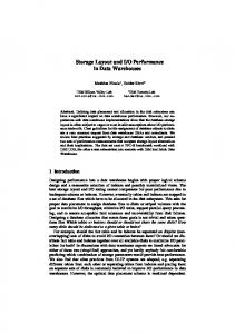
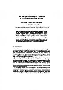
We designed a RCA adder with a various input length to compare between the conventional ternary logic and the proposed ternary one as shown in Fig. 11. This figure shows that the proposed hybrid ternary scheme has 50% of signal transition rate on the average in comparison with conventional ternary scheme. It means that the proposed hybrid ternary scheme shows about half reduction of switching transition. It is large power reduction rate caused by decreasing of signal transition rate of switching rate. As a result, we get the power reduction rate about 23% averages with input length and the power reduction rate increase as the input data length increases in Fig 12. In addition, the circuit shows good power activities, while it has lower operation speed. By above discussion, we have 23% power-delay product reduction according to decrease of switching power activities in Fig 13.
Fig. 11. Comparison of signal transition ratio
Fig. 10. Simulation waveforms with RCA Table2. Comparison of DI encoding methods Encoding Type Dual-rail 1-of-4 Ternary RT/NRT ternary Hybrid ternary
Area (wires/bit) 2 2 1 1 1
Energy (Transitions/bit) 2 1 1 0.75 0.5
Fig. 12. Power comparison of proposed ternary scheme
Proceedings of the 36th International Symposium on Multiple-Valued Logic (ISMVL’06) 0-7695-2532-6/06 $20.00 © 2006
IEEE
Fig. 13. Comparison of power-delay product
6. Conclusions In this paper, we present a new asynchronous encoding using a MVL for reducing the switching activities and the number of wires. We propose two methods. First, we propose RT/NRT encoding using MVL logic to reduce the number of switching activities. It can also contribute to reduce the power consumption of DI asynchronous logic. Second, we propose hybrid ternary data encoding scheme to reduce the number of data communication channel. Even though the MVL logic has a disadvantage in operating speed, the asynchronous circuit using a MVL provides very interesting results for both logic size and power consumption. As the results, the proposed RT/NRT encoding method shows 25% reduction of the signal transition and it achieve the lower power consumption about 27% than the conventional ternary data encoding scheme. In addition, hybrid ternary encoding shows that it achieves the lower power consumption about 30% and energy reduction about 23% than the conventional ternary data encoding scheme. The latter has a significant advantage that it need only two lines for transferring 2-bit datum like an asynchronous circuit with a bundled delay model.
[2] V. Akella, N. H. Vaidya, G. R. Redinbo, "Limitations of VLSI implementations of delay-insensitive codes,” IEEE Proc. 26th Int. Symp. on Fault-Tolerant Computing, pp. 208-217, June 1996, [3] T. Verhoeff, "Delay-insensitive code an overview,” Distributed Computing, vol. 3, pp. 1-8, 1988 [4] Y. Nagata and M. Mukaidono, “B-ternary asynchronous digital system under relative delay,” IEICE Trans. Information and System, vol. E86-D, no.5, pp. 910-919, May 2003. [5] W.J. Bainbridge, W.B. Toms, D.A. Edwards, S.B. Furber, “Delay-Insensitive, Point-toPoint Interconnect using m-of-n codes,” Proc. 9th Int’l Symp. On Advanced Research in Asynchronous Circuits and Systems, pp. 132140, May 2003. [6] T. Felicijan and S. B. Furber, “An asynchronous ternary logic signaling system", IEEE trans. on VLSI, vol, 11, no. 6, pp. 1114-1119, Dec. 2003. [7] R. Mariani, R. Roncella, R. saletti, P. Terreni, “On the realization of delay-insensitive asynchronous circuits with CMOS ternary logic,” Proc, of ASYNC 1997, pp. 54-62, 1997. [8] W. Wang, G. D. Gristede, P.Sanda, S.Y.Wang, D.F.Heidel, “Implementation of a self-resetting CMOS 64-bit parallel adder with enhanced testability” IEEE Journal of Solid-State Circuits, vol, 34, no. 8, pp. 11081117, Aug. 1999. [9] H.T.Bui, W.Yang, Y.Jiang, “Design and Analysis low-power 10-transistor full adders using novel xor-xnor gates” IEEE trans. on Circuit and System, vol, 49, no. 1, pp. 25-30, Jan. 2002.
References [1] S. Huack, "Asynchronous design methodologies: an overview," Proc. the IEEE, vol. 83, no 1, pp. 69-93, Jan, 1995.
Proceedings of the 36th International Symposium on Multiple-Valued Logic (ISMVL’06) 0-7695-2532-6/06 $20.00 © 2006
IEEE