the purely logical behavior of a class (also called the object life cycle). ..... Branch Prediction. in 9th IEEE Real-Time Embedded Technology and Applications ...
Worst-Case Execution Time Analysis from UML-based RT/E Applications Chokri Mraidha, Sébastien Gérard, François Terrier, David Lugato CEA-List 91191 Gif sur Yvette, France {chokri.mraidha; sebastien.gerard ; francois.terrier ; david.lugato}@cea.fr
Abstract. Moving from code-centric to model-centric development seems to be a promising way to cope with the increasing complexity of real-time embedded systems (RT/ES). These systems have various critical requirements that must be validated. Validation is then one of the key-point of their development. Relating to this goal, schedulability analysis methods are usually used to validate the system’s real-time requirements. Most of these methods rely on the knowledge of the Worst-Case Execution Time (WCET) of every task of the system. This paper presents an approach to derive WCET estimates for an application’s UML model.
1
Introduction
The Object Management Group (OMG) has been recently promoting the Model Driven Architecture (MDA) [1], an approach to cope with the increasing complexity of real-time embedded systems. The main idea is to move from code-centric to model-centric development. It relies mainly on UML [2] model refinement and transformation as the basic step of an iterative design process leading to automatic synthesis of the application. For RT/E systems, validation is one of the key point of their development. And relating to this goal, schedulability analysis methods are usually used to validate the fulfilment of those real-time requirements of an application (e.g. deadline, ready time…). Most of these methods rely on the knowledge of the Worst-Case Execution Time (WCET) of every task of the system [3, 4]. This WCET is the execution time of a given task before scheduling, thus this WCET estimate does not take into account possible pre-emption of this task. The scheduler will then use WCET estimates to schedule tasks of the system. The proposition made in this paper is then to give a practical solution to its reader. This solution is based on a method on the one hand, but also supported by tools on the other hand, to quantify WCET. The paper is organized around four main parts. The first one describes related works considering WCET analysis. The following section outlines the UML model on which it is possible to apply the ideas this paper is presenting. The third section
consists then in describing our approach for WCET analysis for UML behavioral models. Before concluding some experimental results of our approach are presented.
2
Related works
Real-time systems and especially hard real-time systems have to meet strict real-time constraints. Missing such constraints can have disastrous consequences. Therefore, a large community aims to supply validation techniques of real-time systems. Most schedulability and performance analysis methods used to validate real-time behavior of applications rely on the knowledge of WCET. Execution time of a program may depend on various factors, for example on the different values that input data of the program may have. Depending on the various values of the input data, a program execution follows different paths. Execution time of the different paths may vary of course depending of the actions to perform. The highest value among all these execution times is called the worst-case execution time. As stated in [5], there are two main families of methods for WCET analysis: static and dynamic methods. 2.1
Static methods
Static methods are independent of input data values and consist in analyzing a program statically without running it. Usually this kind of techniques is divided in two steps: high-level analysis determines all execution paths of a program; and low-level analysis estimates execution time of these paths. Static methods give an upper bound of WCET. The main difficulty that static methods have to overcome is to not overestimate WCET in order to avoid overscaled hardware design of the system. Despite significant research advances in static analysis methods, some difficulties to deal with modern microprocessors architectures and mechanisms [6] (e.g. branch prediction, out of order executions…) remain. Generally static analysis tools rely on simulators of microprocessors rather than on the microprocessor itself to perform WCET analysis. This raises the problem to use a valid and accurate simulator [7]. 2.2
Dynamic methods
Dynamic methods rely on time measurement through testing techniques. These methods are data-centric and consist in measuring a program execution time on a real system or with a simulator, and this for all possible input data values, which is of course not possible for infinite domains. To determine WCET with a dynamic method we need both following points: (1) a technique to measure execution time of the application; (2) and a way to find the input data set having the largest execution time. If we measure the application execution time on a real system we can exploit internal counters provided in some microprocessors (e.g. Time Stamp Counter (TSC) register on Pentium microprocessor). If we do not have the real system hardware target platform, we can execute the application on a simulator modeling the hardware
of the targeted platform on the one hand and providing a facility to calculate execution time on the other hand. In order to have reliable results in the latter case, the main difficulty is to have an accurate and valid simulator [7]. After determining the technique of measurement, we need to find the input data set triggering the behavior we want to evaluate. Test approaches can be used to this end. Measuring execution time for all possible values is possible for very simple systems having limited possible input values but not possible for large systems. This set of test cases can also be automatically generated. Even if we cannot cover all test cases and then we have not found the test case having the longest execution time, this technique gives a lower bound of WCET. To determine the test case having the longest execution time, we can use symbolic execution of the system that could propagate an evaluation of the calculus complexity. The idea is to have tests covering all possible execution paths of our system. This technique is part of our methodology for calculating WCET, it will then be detailed in the following sections.
3
RT/E Applications modeled in UML
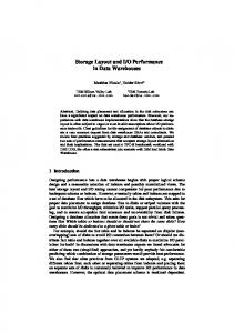
Application models are built according to the Accord/UML methodology [8, 9]. The purpose of this paper is not to describe in minute details the approach. We focus here on the behavioral part of the methodology. This is indeed the main model used for performing schedulability and performance analysis [10]. Unlike other UML-based approaches for RT/ES development, as depicted in Figure 1, Accord/UML implements separation of behavioral concerns around both control and algorithmic aspects [11]. In this way, the reusability and maintainability of the developed applications are considerably improved. The control aspect depicts the purely logical behavior of a class (also called the object life cycle). This is modeled by a specialized UML state machine, the protocol state machine. The second aspect of the global behavior modeling of a class is its algorithmic dimension. The description of this dimension is fully postponed to the operation level of the class model. The algorithmic aspect is modeled using an action language [12] mapping the UML action semantics standard. Actually, when dealing with real-time applications, it is very useful, for simulation or prototyping for example, to be able to model executable models with enough modelling details. For that purpose UML offers a particular package that defines in minute details how to model all actions of an application and obtain also a complete executable model. The higher-level entity of this package that is also the link with other model elements of the UML is the Procedure concept: “A procedure is a group of actions caused to execute as a unit.” Procedure is used either to specify a method body in a specific programming language, or within the context of state machine, to specify effects whenever a state is entered, exited, within a do-activity, or when a transition is fired. The Actions package consists in several sub-packages defining: the basics for Action and Procedure. A Procedure consists of actions that exchange dataflow via In-
putPins and OutputPins; the recursive structures from which it is possible to define more complex actions from more primitive ones; read and write actions that define how to create/delete objects and consult/modify their features, i.e. attributes, variables or links; computation actions that define how to transform data. Computation actions are used to model essentially mathematical functions; high-level actions that ensure a sub-action to be applied on a set of elements; messaging actions that define synchronous calls, asynchronous calls, broadcasting, etc; jump actions that define how to quit a main flow of control in order to continue in the context of a different flow of control. However, the standard focuses on defining the abstract syntax and the semantics of the UML action language. It does not provide any concrete language mapping with this proposed semantics! If one wants to build executable UML models it is then necessary to choose/create a notation (textual and/or graphical) and to define its mapping with elements of the abstract syntax defined in the various Action sub-packages outlined previously. Currently, there are few proposals offering this possibility [1315]. In order to be able to have executable models, we have defined the Accord/UML action language notation [12] which is given in two formalisms: a textual one that can be edited directly in the model and a graphical one based on UML activity diagrams that can be drawn in a UML modeler. Both views are equivalent. Indeed, for some usage, a textual definition of an operation is easier to use. In other cases, the graphical view is more easily understandable. All actions necessary to model applications are specified in [12] and also in an Accord/UML profile for action language that has been defined and implemented to clearly specify UML semantic variation points [16]. m 1()
Class
S1
m 1()
m 1()
S2
Class Class behavior (Structural aspect) (Control aspect)
Operation behavior (Algorithmic aspect)
Figure 1: Accord/UML behavioral model
The Accord/UML action language is made of conditional actions, loop actions, group actions, messaging actions, etc. All elementary actions required for real-time systems modeling with Accord/UML are defined. Figure 2, depicts examples of conditional actions. The first one is an “if-then-else” elementary action and the second one is a “switch”. This action language allows us to have a complete executable model independent of any given programming language. Specific programming language code like, C, C++ or java can then be generated from these behavioral models.
Graphical view
Textual view Action 0 ;
Action 0
if (condition true) Action 1;
[condition false]
[condition true]
else Action 1
Action 2;
Action 2
Endif Action 0 ; Action 0
switch (variable) [variable == value1]
Action 1
case value1 :
[else]
[variable == value2]
Action1;
[else]
case value2 : Action 2
Action 3
Action2; default : Action 3; endswitch Action 4
Action 4;
Figure 2: Examples of conditional actions in the ACCORD/UML action language
In this study we will focus on WCET analysis of the algorithmic aspect described previously.
4
WCET analysis of modeled algorithms
This section describes our methods for WCET analysis of Accord/UML behavioral models. We will focus this study on the algorithmic aspect of the behavioral model and then determine WCET for each operation of classes of the application. We are going to present two approaches for WCET analysis of our models: a static approach and a dynamic approach. If we have accurate platform information and especially WCET of elementary actions of the action language, WCET can then be determined statically. Our static analysis approach consists in statically analyzing the behavioral model. This approach relies on the knowledge of values of WCET for each elementary action of the action language [12], and symbolic execution of our UML behavioral model. Information relating to WCET of each elementary action of the Accord/UML action language is added to the initial UML model. To perform this static analysis we use the Agatha toolset [17], which calculates all symbolic execution paths of our model. Otherwise, to overcome the lack of information on platform architecture and difficulties of static approaches to take into account complex mechanisms of modern architectures, we will present a dynamic WCET analysis. The dynamic analysis approach consists in analyzing the behavioral model at runtime. This approach relies on
testing all execution paths of an operation of the model, and then by measuring the execution time on a particular platform for each path, we determine an estimation of WCET for the given operation on a given execution platform. The Agatha toolset is used to determine all execution paths and give test cases for each path. First, we will present the automatic test case generator we are using to statically analyze WCET in a static approach and compute the various execution paths to evaluate for a dynamic approach of execution time evaluation. 4.1
The Agatha toolset
The toolset translates UML models to its input formalism and computes all symbolic behavior of the system by symbolic calculus [17]. The tool originally generates test sets to allow for determining whether the software implementation is conformant to its specification. As it always generates a symbolic execution tree, Agatha permits deep investigation into the system’s behaviors. To produce these results, Agatha has to deal with combinatorial explosion in combining different techniques such as symbolic calculus, detection of interleaving, constraint solving, rewriting procedures, polyhedral calculus. For WCET analysis, the first step is to translate the UML model into the input language called STGA (Symbolic Input Transition Graph with Assignment). The resulting translation algorithm is implemented in Objecteering UML modeling tool. Translation details of UML models into the Agatha formalism is beyond the scope of this paper, so we briefly present the Agatha formalism, then reader should refer to [18] for further details. TRANS FROM State1 TO State2 WHEN input(x) PROVIDED x>0 OUTPUT ok BEGIN a:=a+x END;
State1 ?input(x) [x>0] !ok a:=a+x; State2
Figure 3: Example of an STGA transition
The tool uses symbolic execution as defined by [19]. In fact the major drawback of numeric techniques is the combinatorial explosion due to variable domains. These domains can be huge, sometimes even infinite. Symbolic calculus allows the handling of such domains because computing all the behaviors is not equivalent to trying all the possible values for inputs. Instead of giving values for inputs, they keep their status of symbol all execution long. Currently Agatha handles only expressions of the first-order logic. Although this limitation does not concern a large part of embedded real-time application’s algo-
rithms of the industry, we are working on Agatha enhancement to be able to deal with more complex expressions. Now let us set out static and dynamic WCET analysis using this toolset. 4.2
A static WCET analysis approach
Our static analysis approach consists in statically analyzing the UML behavior model describing the algorithms of an application. This approach relies on the knowledge of WCET values for each elementary action of the action language [12] on a given platform of execution. This set of WCET values for a given platform can be obtained by several ways like using a runtime measurement tool or a static analysis for instance. A symbolic value is attached to each elementary action. For instance, AssignAction corresponds to an assignment action; AddAction corresponds to an addition action; TestAction represents a test action which result is a boolean; AsynchronousCallAction represents an asynchronous call action; and so on. We can note that WCET of this latter corresponds to the time necessary to put arguments on the stack and make the call; contrary to a synchronous operation call, the WCET of the called operation is not taken into account for an asynchronous one. In the next section, we present an overview of static WCET analysis with the Agatha toolset and illustrate this approach with a simple example. 4.2.1 Process overview The first phase of static WCET analysis is platform independent and consists in computing all possible symbolic expressions of WCET for a given operation. This is done by symbolic execution of the operation using the Agatha toolset. To achieve this goal, as illustrated in Figure 5, a WCET variable is added to the operation model of Figure 4. This variable can be assigned only by symbolic expressions of WCET of elementary actions. The annotated UML behavioral model is then translated into the Agatha internal language (STGA). The symbolic execution is then provided by the Agatha tool. We finally obtain a set of all possible symbolic values for WCET. The WCET for a given platform is then determined by replacing symbolic expression of each elementary action by its given numerical values on the targeted platform. 4.2.2 Illustration through an example To illustrate the static WCET analysis process proposed previously, let us consider the very simple example depicted in Figure 4. For readability reasons, this figure represents only a part of an operation. After a variable assignment a test is done on the value of the variable x and depending on its value, two branches are possible.
x := a
[x > 10]
[x 10. We obtain then two possible WCET expressions: 1. W1 - WCET = 2*WCET_AssignAction + WCET_TestAction + WCET_AddAction (for x≤10 branch) 2. W2 - WCET = 2*WCET_AssignAction + WCET_TestAction (for x>10 branch).
In this simple case, WCET corresponds to the x≤10 branch. If a relation order between WCET of elementary actions is specified, Agatha may be able to give us directly the symbolic WCET. 4.2.3 Discussion This WCET static analysis technique may lead to an overestimated WCET for some kinds of platforms. This is due to the fact that our approach does not take into account some architectural mechanisms like instruction level parallelism, caches, branch predictions or out-of-order execution. The WCET given by this approach for these kinds of platforms may then lead to an over sizing of the hardware part of the system. By the way, this WCET analysis approach provides a safe and not overestimated WCET for microprocessors that do not have the architecture mechanisms cited above. On top of that for critical real-time systems, time execution predictability is a fundamental point. The modern architecture mechanisms seen above introduce execution time unpredictability [6]. Architectures ensuring execution time predictability are preferable for critical real-time systems. Our WCET analysis approach provides a safe WCET, which can be used for schedulability or performance analysis of critical real-time applications. Another point is that our WCET analysis approach is integrated in a model-based tool chain providing then an automatic estimation of the WCET from the UML model. The symbolic WCET is platform independent; a simple replacement of elementary actions symbolic values by numeric values is necessary to give the WCET on another platform, this makes WCET analysis easily retargetable. 4.3
The dynamic WCET analysis approach
This section presents the dynamic WCET approach. In a first part we present the dynamic analysis process overview. In a second part we present in more details the last phase of this process, which is the measurement of execution time. 4.3.1 Process overview As depicted in Figure 6, the dynamic WCET analysis process is divided in two main steps. First step is platform independent. The UML model is automatically translated into Agatha (STGA) formalism [18]. The Agatha toolset is then used to automatically generate a set of test cases covering all execution paths of the application. Each path is characterized by a Path Condition (PC) which is a set of constraints on parameters of the operation. Actually, each PC of each operation corresponds to an equivalence class of test cases values for the operation. It is important to note that the constraint solver used by Agatha gives us a single value for each variable of the path condition [20]. It is also impossible to ensure that another value for that path condition will not result in a greater execution time. For this reason, the dynamic approach may supply a lower bound of WCET than the static WCET analysis described in the previous section. The second step is platform dependant. It consists firstly in code generation from the UML model, then its compilation and finally execution time measurement of the
operation using all test cases generated within the first step. The WCET is then deduced from these tests executing each test case and measuring execution time on the targeted platform. But how can we measure the execution time with sufficient accuracy and disturbing as little as possible the measured process? AGATHA
TEST CASES
STGA
m1() Cla
a>b and bb]
[a10]
x := 5*(a+2*b)-3a*a
[xb) and (a>10)
20
5
(a>b) and (a≤10)
9
5
(a≤b) and (b>10)
10
20
(a≤b) and (b≤10)
5
9
The second step consists in executing the operation on the target platform and its execution time measurement for each test case described in the Table 2. 4.3.3.2 Measurement of execution time As it is well known that timing routines of general purpose operating systems has a low resolution, we have measured execution time using the microprocessor clock cycles internal counter (TSC register) for this example.
Execution time in ms
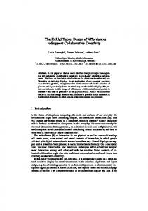
We have noticed that measuring execution time of a single simple operation call is not accurate at all, and then results of measurements that are not relevant. Then, to cope with this problem, we have measured execution time of several calls of the operation. In order to prevent the cache influence for our usage of loops of call, we have used cache invalidation instruction; we have then a cold start for each loop iteration. Figure 11 shows results of the measurement of execution time on the four path conditions of the application. Execution time grows linearly with the number of iterations. This chart shows clearly that the third test (a=10 and b=20 on Table 2) has the longest execution time. 200 150 100 50 0 1000
2000
3000
4000
5000
6000
Number of iterations PC1 PC2 PC3
7000 PC4
Figure 8: Measure of execution time of the four path conditions found by Agatha
Worst-Case Execution Time of this operation corresponds then to the gradient of this chart. Then WCET of the operation of Figure 7 is 27 µs. 4.3.4 Discussion As in the static approach presented in the previous section, in this dynamic WCET analysis all possible execution paths are first derived using symbolic execution over variables. To obtain the execution time for a particular execution path it is repeatedly measured on the target platform. Although all test cases are covered, this technique may lead to a lower bound of the WCET, thus the provided WCET may be unsafe. Contrary to the static approach, this dynamic approach does not target critical realtime systems but it can easily fulfill soft real-time systems requirements. Our approach is integrated in a tool chain and it is largely automated. Handling of architectural mechanisms of modern microprocessors is better in this dynamic approach rather than the static one. This is due to the fact that the measurements are made on the target platform itself. It is important to note that the measurement part of this dynamic WCET analysis approach is platform specific. The platform description model includes all platform components going from hardware ones like the microprocessor to software ones like compiler optimization flags that are used.
5
Conclusions and future work
Market constraints and embedded real-time systems complexity are drastically increasing, thus forcing engineers to apply new principles/techniques. Among others, model driven development offers very promising solutions to these issues. The knowledge of WCET is fundamental for the design of embedded real-time systems. The WCET is indeed used for schedulability analysis or performance analysis of these systems. However in our knowledge, currently there is no existing framework of WCET analysis for UML models. In this paper we have presented two approaches of WCET analysis for UML models. The first one is a static WCET analysis approach relying on a detailed platform model. Using symbolic execution and WCET of elementary actions, this approach gives us a safe WCET. It is dedicated to critical as well as soft real-time systems with hardware architecture without elaborated architectural mechanisms. The second approach presented is the dynamic WCET analysis. This approach combines automatic exhaustive test cases generation based on symbolic execution, code generation, and execution time measurements on the targeted platform. It is dedicated to soft real-time systems, but contrary to the static approach, this one deals with modern architecture mechanisms. These two approaches are integrated in an UML-based development tool chain. They are largely automated and can be applied on a wide range of current embedded real-time systems. Our future work will consist in enhancing the static approach in order to be able to take into account modern architectural mechanisms, and thus provide a safe WCET for critical real-time systems using hardware with these advanced architectural mechanisms.
6
References
[1] OMG, MDA Guide Version 1.0.1. 2003, OMG. [2] OMG, Unified Modeling Language: Superstructure Version 2.0. 2003. [3] D.C. Petriu and C.M. Woodside, Performance Analysis with UML: Layered Queuing Models from the Performance Profile, in UML for Real: Design of Embedded Real-Time Systems. 2003, Kluwer Academic Publishers. [4] Marco Di Natale and Manas Saksena, Schedulability Analysis with UML, in UML for Real: Design of Embedded Real-Time Systems. 2003, Kluwer Academic Publishers. [5] Antoine Colin, et al., Computing worst-case execution times: a state of the art. 2002, IRISA. [6] Jakob Engblom. Analysis of the Execution Time Unpredictability caused by Dynamic Branch Prediction. in 9th IEEE Real-Time Embedded Technology and Applications Symposium (RTAS 2003). 2003. Toronto, Canada. [7] Jakob Engblom. On Hardware and Hardware Models for Embedded Real-Time Systems. in Embedded Real-Time Systems Workshop. 2001. London, UK.
[8] A. Lanusse, S. Gérard, and F. Terrier. Real-Time Modeling with UML : The ACCORD Approach. in "UML98" : Beyond the Notation. 1998. Mulhouse, France: J. Bezivin et P.A. Muller. [9] S. Gérard, F. Terrier, and Y. Tanguy. Using the Model Paradigm for Real-Time Systems Develoment: ACCORD/UML. in OOIS'02-MDSD. 2002. Montpellier: Springer. [10] Trung Hieu Phan, et al. Scheduling Validation for UML-modeled Real-Time Systems. in ECRTS 2003. 2003. Porto, Portugal. [11] Chokri Mraidha, et al. A Two-Aspect Approach for a Clearer Behavior Model. in The 6th IEEE International Symposium on Object-oriented Real-time distributed Computing (ISORC'2003). 2003. Hakodate, Hokkaido, Japan: IEEE. [12] Chokri Mraidha, et al., Action Language Notation for ACCORD/UML. 2003, DTSI/SLA/03-190/MC/ASG CEA. [13] ITU-T, Languages for telecommunications applications - SDL combined with UML. 1999, ITU-T: Geneva, Italy. [14] Mellor. Advanced Methods and Tools for Precise UML: Vision for the Future. in OOPSLA workshop pUML. 2000. Denver. [15] Ian Wilkie, et al., UML ASL Reference Guide. 2001, Kennedy Carter. p. 90. [16] Chokri Mraidha and Sébastien Gérard, ACCORD/UML Profile for an Action Language. 2003, CEA. [17] C. Bigot, et al. Automatic test generation with AGATHA. in TACAS. 2003. Warsaw, Poland. [18] D. Lugato, et al., Validation and automatic test generation on UML models : the AGATHA approach. special issue of the STTT (Software Tools for Technology Transfer), 2004. [19] Lori A. Clarke, A System to Generate Test Data and Symbolically Execute Programs. IEEE Trans. Software Eng, 1976: p. 215-222. [20] University of Maryland,The Omega Library version 1.1.0,http://www.cs.umd.edu/projects/omega.