Experiences with Precise State Modeling in an Industrial Safety Critical System Nina Holt1, Bente Anda1, Knut Asskildt2, Lionel C. Briand1, Jan Endresen2, and Sverre Frøystein2 1Simula Research Laboratory, P.O. Box 134, NO-1325 Lysaker, Norway {ninaeho, bentea}@simula.no,
[email protected] 2 ABB Corporate Research Centre, P.O. Box 90, NO-1361 Billingstad, Norway {knut.asskildt, jan.endresen, sverre.froystein}@no.abb.com
Abstract. The development of safety critical systems is a complex and challenging task. There are many claims regarding how precise modeling, either with the UML or other modeling notations, can yield benefits in terms of more rigorous specifications and designs. This paper reports on experiences from applying statechart-driven UML modeling in the development of a safety-critical system at ABB. The primary lessons learned from the study are related to the impact of precise modeling on the ease of transitioning to design.
1 Introduction There are many proponents of precise modeling in academia, the main argument being that precise specifications and designs need to be defined before development can start. However, industry has not yet widely adopted model-driven development and it is therefore important to understand what the benefits and challenges are when adopting such practices. Furthermore, one might expect such benefits to be maximized in the context of safety-critical software with higher dependability requirements. There is a large difference between a sketch of a specification and an implementation. The goal of using UML in the specification of safety-critical systems is to obtain specifications that are detailed enough to facilitate the transition to implementation and limit rework in the late stages of development. As part of a software process improvement initiative in ABB, we had the opportunity to conduct a study on precise modeling with the UML in the specification and design phases of a safety-critical system. This paper reports on lessons learned from this experience, emphasizing statechart-driven modeling as the safety-critical system under study has a state-driven behavior. The paper is organized as follows: Section 2 presents the project context. Section 3 describes the modeling process. Section 4 reports the lessons learned, and Section 5 concludes.
2 Nina Holt, Bente Anda, Knut Asskildt, Lionel C. Briand, Jan Endresen, and Sverre Frøystein
2
Context
This section describes the context of the study: the company (ABB), the software process improvement project, the safety-critical system which is the focus of this study, and the development method.
2.1 Organization ABB is a global company that operates in approximately 100 countries with 100,000 employees. A primary business area concerns power and automation technologies for which ABB develops software and hardware. The ABB Corporate Research Center in Norway, NOCRC, is one of ABB’s eight research centers worldwide. Their interests concern industrial communication, human-machine interaction, control and optimization of industrial processes, and instrumentation and operation of machines and processes. The research center supports the business units of ABB through projects and technical studies.
2.2 Software Process Improvement Project ABB Corporate Research in Norway has initiated a software process improvement initiative with the aim of improving UML modeling practices throughout the company. 1 This initiative is supported by the Norwegian Research Council through the project EVISOFT (EVidence based Improvement of SOFTware engineering), and it is conducted in cooperation with researchers from Simula Research Laboratory. The current project was initiated to investigate which UML diagrams may be beneficial to ABB in the process of going from the specification to the implementation phase. It provided a unique opportunity to assess the usage of precise, statechart-driven UML modeling in a realistic safety-critical development environment. A Technical Requirements Specification, developed by the business unit in cooperation with the scientists from NOCRC, was the starting point for developing a common understanding of the system. The modeling was a cooperative activity between Simula and NOCRC. Each modeling activity was closely monitored and followed by an introspective analysis of what happened. Based on these activities, several lessons are drawn regarding the benefits and challenges of precise UML modeling.
2.3 System In order to satisfy the safety standards (e.g. EN 954 and IEC 61508 [2]) and enhance the safety-critical behaviour of their industrial machines, ABB develops a new ver1
Previous results of the process improvement initiative work are reported in [1].
Experiences with Precise State Modeling in an Industrial Safety Critical System 3
sion of a safety-critical system for supervising an industrial machine. The focus of this study is a subsystem of this system, called the Safety Controller. The main function of the Safety Controller is to supervise the status of all safety related components interacting with the machine, and to initiate a stop of the machine in a safe way when one of these components requests a stop or if a fault is detected. It shall also interface with an optional safety bus to enable a remote stop and a reliable exchange of system status information. The system will be configurable with respect to which safety buses the system can interact with.
2.4 Development Method In the project under study, the original specification was based on functional decomposition, not object-oriented analysis. The overall system was iteratively decomposed into functional blocks, each carefully described in terms of input-output mappings and occasionally informal state models. One of the blocks, called the Mode Functional Block, represented a state model for the functionality of changing between the modes that the machine can operate in. This high level state model, which was not a precise statechart, was our starting point. Development follows a V-model, also adopted by safety standards such as IEC 61508. An important activity for complying with the safety standards is hazard analysis. In this project, the hazard analysis consists in identifying main safety threats the machines can cause to their environment, the conditions under which these threats can manifest themselves, and whether they are indeed possible given the system implementation. The Safety Controller will supervise and handle these threats. The original specifications focused on the expected behavior of the system with little emphasis on explicit error and exceptional scenarios other than specifying that certain safety standards shall be complied with. Error and exceptional scenarios are typically identified later in the project, as more details become apparent, and result from a hazard analysis activity. One of the main reasons for this is that a first version of these systems are typically designed and implemented before a complete specification of all error and exceptional scenarios are known.
3
Statechart-driven Modeling
Statechart modeling drives the design of the Safety Controller. Section 3.1 presents our precise statechart-driven modeling activities. Section 3.2 describes partial results of the modeling process: the statechart and class diagrams.
4 Nina Holt, Bente Anda, Knut Asskildt, Lionel C. Briand, Jan Endresen, and Sverre Frøystein
3.1 Modeling Process The modeling process has been iterative, mainly due to the fact that all details regarding the functionality of the system were not known at the outset of the project. Many unexpected (error) states, transitions, and operations were identified and formally described while modeling. Iterative modifications to the Technical Requirements Specification were necessary and triggered reviews with the business units. The following are the main steps of the modeling process: 1. Devise a context diagram to model the environment in which operate the system 2. Identify a control class and interface classes from the context diagram 3. Identify states and invariants for the control class 4. Identify transitions and guard conditions (note: steps 2 and 3 can lead to defining new class attributes) 5. Identify actions on transitions and states, which usually lead to additional public operations in classes 6. Iterate to any of the previous steps The system context class diagram is a part of the methodology in Gomaa [3]. The context diagram helps us understand the interfaces between the system and the external environment and, hence, is useful for defining interface classes in the class diagram. In our project, the context diagram helped precisely identify the external devices that the system would interact with. An extension for UML statecharts of the state-design pattern [4] was then applied in order to construct a class cluster implementing the Safety Controller statechart. The extended state-design pattern provides a template on how to implement a UML statechart in such a way as to improve traceability from the model to the implementation and facilitate change. It extends the original state pattern by specifying how to implement state and transition actions. Furthermore, the class diagram was augmented with pre- and post conditions of operations described using the Object Constraint Language (OCL). This helps provide precise operational specifications for class operations and usually leads to refinements of the class diagram.
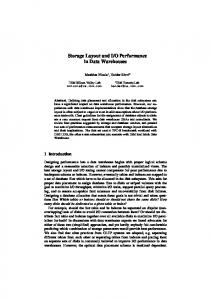
3.2 Precise Statechart Model Figure 1 shows the statechart of the Safety Controller. Due to space and confidentiality constraints, the statechart is not complete with respect to state names, event names and actions on transitions or in states. We only present enough details to illustrate our modeling process 2 . 2
The implementation of the system is still in progress at the time of writing, hence there may still be changes to the specification, and the statechart may therefore not be an exact representation of an actual ABB system.
Experiences with Precise State Modeling in an Industrial Safety Critical System 5
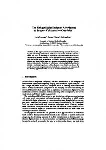
By precise UML statechart modeling we mean that OCL [5] is used to specify state invariants, guard conditions, and pre- and post conditions of operations involved in call events. The statechart consists of two main superstates, namely Operational and Suspended. The machine is allowed to be operated in Operational. In the Suspended state the machine is stopped. Errors are logged in the Error state. Operational consists of three mode states that reflect the ways of how the machine can be controlled: Automatic, Operator, and OperatorFullSpeed. The last mode allows the machine to be manually controlled running at full speed. However, it is necessary to go via the confirm states before entering a different mode state. Hence, there are additionally three confirm states, one for each mode. The OperatorFullSpeedConfirm and AutoConfirm are superstates with substates that wait for the operator to push a confirm button which takes the Safety Controller to a state where it waits for a confirmation from the Main Controller before it transitions to the selected mode. This particular way of handling the switch between these modes is due to the potentially high speed of the machine in OperatorFullSpeed and Auto. The different stops will cause a transition from Operational to Suspended. When all stops are handled, the Safety Controller transitions back to the substate in Operational where the last stop occurred. This means that the machine can resume operation. An emergencyStop is handled differently than the other stops. Hence, the explicit modeling of this stop type in the statechart. The emergency button must be released to proceed from WaitRelease to WaitReset. The operator must physically give a confirmation by pushing the machine confirmation-button. This event will cause the transition back to Stop. If another emergencyStop is detected before the machine confirmation-button is pushed, the Safety Controller transitions back to WaitRelease. The statechart was developed concurrently with class public interfaces. These consist of a state-dependent control class (that will eventually implement the statechart) and interface classes interacting with the numerous external devices and (sub) systems. We additionally use the class stereotypes defined by Gomaa [3] in the class diagram shown in Figure 2. By using the extended state design pattern [4], we derived the class diagram shown in Figure 2. It consists of a class SafetyController that represents the system controlling the machine. The SafetyController is assigned all responsibilities for handling the state behavior. The SafetyController can be in one of several states: Suspended, Operational or Error. The SafetyController will act differently depending on what state it is in. An abstract class State represents the states of the SafetyController, and declares an interface common to all classes that represent different operational states. The subclasses of State implement state-specific behavior, which means that they provide operation implementations that are specific to every state (and possibly empty) of the SafetyController. The interface classes (e.g. the ConfigFileInterface) handle the communication between the state-control class and the external classes.
6 Nina Holt, Bente Anda, Knut Asskildt, Lionel C. Briand, Jan Endresen, and Sverre Frøystein
Example a Operational
setMode(auto) setMode(operatorFullSpeed)
OperatorFullSpeed Confirm
AutoConfirm
Operator
pushMachineConfirm()/ machineConfirm:= true
WaitOperatorFS Confirm
WaitAuto Confirm
lse WaitAutoMachine := fa firm Confirm eCon in h c ma m()/ onfir odeC autoM
WaitOperatorFS MachineConfirm
Example c OperatorFullSpeed
[no ts afe gu and ard not ] sof twa re
Suspended
Sto p]
Example d after(1s)
Stop
stop() [safeguard and not softwareStop]
EmergencyStop
WaitReset
softwa reStop ]
sto p() [sa fe g uar d
Auto
emergencyStop()
WaitRelease
stop() [safeg uard a nd
H
ille gal Va lue s()
Example e
Error
illegalValues()
SoftwareStop
Example b
Figure 1 Safety Controller Statechart 3
4
Lessons Learned
This section reports the main lessons learned from modeling of the Safety Controller using a precise, statechart-driven modeling methodology. 4.1
More Complete Specifications
Through precise modeling, we quickly realized that the original specification was incomplete. By going through all possible states and transitions, and defining precise state invariants as well as defining actions, transitions and states using predefined operations and states, we detected many scenarios that had not previously been considered. We thus achieved a more complete, and hence safer specification. Representative improvement examples from Figure 1 are provided below:
3
Note that due to confidentiality constraints Figure 1 does not show all states and events.
Experiences with Precise State Modeling in an Industrial Safety Critical System 7
ConfigFileInterface initialize() getConfigVariables() setConfigVariables()
SafetyController State setMode() pushMachineConfirm() autoModeConfirm() illegalValues() stop() emergencyStop() machineConfirm:=true machineConfirm:=false
setMode() pushMachineConfirm() autoModeConfirm() illegalValues() stop() emergencyStop()
Suspended
emergencyStop()
WaitReset
Error
setMode() pushMachineConfirm() autoModeConfirm() stop() illegalValues()
SoftwareStop
EmergencyStop
Stop
Example i Example g
Operational
stop() emergencyStop() illegalValues()
Example f
stop()
WaitRelease
PendantControlStationInterface initialize() setEnableDevice() getEnableDevice() acquirePendantControl StationConfirm()
OperatorFullSpeed Confirm
Example h
OperatorFullSpeed
Operator
Auto
WaitOperatorFSMachine Confirm
AutoConfirm setMode() pushMachineConfirm() autoModeConfirm()
setMode()
WaitOperatorFSConfirm
emergencyStop()
WaitAutoMachineConfirm pushMachineConfirm()
WaitAutoConfirm autoModeConfirm()
Figure 2 Class Diagram 4
1. New transitions between states were identified: (1) transitions between the confirm states which can occur if the mode is changed again before the target mode is reached (Example a), (2) transition from WaitReset to WaitRelease in the case where another emergencyStop event is detected when entering the EmergencyStop state (Example b). 2. The specification of the order of the events that is necessary to change mode is more precise: The transitions between AutoConfirm and Auto require a physical confirmation by the operator from WaitAutoMachineConfirm to WaitAutoConfirm (Example c). 3. All the events that cause the machine to stop were identified (Example d). There are different types of stop events, for example emergency switches, enabling switches, light curtain devices and online hardware testing not OK or communication online testing not OK. The safeguard variable shown in some of the statechart’s guard conditions is a derived Boolean class attribute that is set to true once a stop event occurs which would cause the transition to the Suspended state.
4.2
Complexity and Importance of Error Scenarios
At the outset of the modeling process, normal condition scenarios were the main focus as these were described in the original specification. However, as a conse4
Note that due to space and confidentiality constraints Figure 2 does not show all the operations.
8 Nina Holt, Bente Anda, Knut Asskildt, Lionel C. Briand, Jan Endresen, and Sverre Frøystein
quence of the precise statechart modeling process we soon realised that in the Machine Safety subsystem, error scenarios represent a substantial part of the complexity, and are crucial in ensuring the safety of the overall machine control system. System errors may correspond to illegal events or illegal parameters to events, e.g., an illegal mode value. In order to make a robust system, every possible illegal event (corresponding to a hardware or software error) in every state must be considered. A transition to a safe state must then be ensured and error information must be logged so that a safe restart of the system can be initiated (Example e). 4.3
Easier Transition to Design
Precise statechart-driven modeling facilitates the transition from specification to design. It helps precisely identify the required class public interfaces and attributes, and the responsibilities (contracts) of operations. Indeed, as actions, events, and guard conditions are defined, it is then necessary to define class operations and attributes to match them. Innovative, safety-critical systems are often specified and designed incrementally; a design and an implementation typically exist while the specification is still incomplete. As a result, traceability between the specification, design, and implementation must be ensured and organized in such a way that changes to the specifications will result in easy changes to the design and implementation and consequently facilitate verification and testing. Traceability is a main principle underlying all safety certification work. We adopted an extended design pattern strategy here as explained in Section 3. This led to a direct traceability between states and classes and a predetermined location for operations corresponding to call events and actions that minimize code redundancy, thus facilitating changes. Figure 2 shows the state dependent control class SafetyController (Example f) and the State class (Example g) with subclasses Operational, Suspended and Error (Example h) that were identified based on states of the statechart in Figure 1. See Section 3 for further explanations of how the classes were derived. 4.4
System Boundary
Specifying a context diagram helped identify interface classes early on and facilitated the specification of many transitions and state actions as calls to these interface classes. The context diagram also led to a more precise and specific problem domain terminology for describing external devices and inputs. This facilitated the interactions among the stakeholders involved in the modelling activities. We encapsulated the state behaviour and interfaces to external devices, systems, and users in different classes. Since the communication protocols to external devices and systems will likely change during the lifespan of the software control system, such distribution of class responsibilities will minimize the impact of changes in its boundary. For example, any change in the communication protocol to a device (e.g., sensor) will be limited to the interface class dedicated to that device, and any change
Experiences with Precise State Modeling in an Industrial Safety Critical System 9
in the state behaviour of the subsystem is limited to changing the subclasses implementing that behaviour [4]. Examples of interface classes are shown in the class diagram in Figure 2 (Example i). 4.5 Transition from Functional Decomposition to the Object-oriented Paradigm The transition from the functional paradigm to the object-oriented paradigm was difficult for some of the designers and developers: 1. Difficulties in understanding the difference between a functional and an objectoriented decomposition led to difficulties in assigning responsibilities to classes and therefore confusion in the statechart definition of the state-dependent control class (e.g., actions as calls to interface classes). 2. The abstract concepts related to statecharts (e.g., state invariants, actions) are inherently difficult. In particular, the differences between actions and events, events and the state attributes recording them were particularly difficult to grasp. 4.6
Inadequacy of Modeling Tools
In this project we applied a commercially available UML modelling tool: SmartDraw [6]. Though this is not an IDE, it has good support for drawing UML diagrams. For the purpose of this project where we spent hours iteratively modifying diagrams in group meetings, we found that SmartDraw was the best option as the learning overhead to draw diagrams was rather low and quick, iterative changes to the diagrams could be more easily performed than with some of the commercial IDEs at our disposal. Modeling the Safety Controller involved five stakeholders over many hours of discussions during which the specification changed and the UML model was updated. Our experience is, however, that current UML tools do not provide sufficient support for iterative, group modeling. The most prominent problems were: 1. Handling iterative development of statecharts: Our modeling process was very iterative and many details in the specification were not known at the outset. Consequently there were many changes to the statechart and sometimes also a need to go back to a previous version. We found that it would have been very useful to have a modeling tool with support for handling different versions of the statechart including the tracking of changes and their related information (e.g., date and authors). It would also be useful to be able to specify explicitly where the model is incomplete. 2. Merging two versions of the same statechart: In addition to working as a group, concurrent individual work was also taking place on the model and support for merging different versions of the same statechart would have been very convenient. 3. Scalability of diagrams: Even though this system is relatively small, the statechart soon got quite large, and it was difficult to view all details on one screen. We therefore experienced that it would have been helpful to have a tool that en-
10 Nina Holt, Bente Anda, Knut Asskildt, Lionel C. Briand, Jan Endresen, and Sverre Frøystein
ables showing and hiding details from the diagram. A suggestion would be to provide a mechanism for the user to click on a state to exhibit its inner details (e.g., substates and their transitions). To the authors’ knowledge, based on experience using most of the major UML modeling tools, the functionalities listed above are not fully available in commercially available UML IDEs.
5
Conclusions
Precise modeling as the basis for development in industry is not yet a widespread practice. This paper has presented a study conducted at the ABB Corporate Research Center in Norway where state modeling with UML was used as the driver for specifying and designing the subsystem of a safety system for controlling a machine. The study reports experiences that we believe are helpful in order to understand the cost and benefits of precise modeling of safety-critical systems. At a high level, the lessons learned from this modeling experience are first of all that we can achieve a more complete and thus a safer specification through precise state modeling. Second, such state modeling facilitates the transition from specification to design in such a way that the impact of future changes is minimized: modeling guidelines ensure the encapsulation of the interfaces to external devices and there is complete traceability from the statechart model to the design classes. Acknowledgments The reported work was funded by The Research Council of Norway through the industry project EVISOFT (Evidence based Improvement of SOFTware engineering).
References 1.
2. 3. 4. 5. 6.
Hansen, K., Anda, B., and Gullesen, I.: Experiences with a UML-based Development Method for SIL products. In: CSDUML 2005, The 4th International Workshop on Critical Systems Development Using Modeling Languages (2005) IEC 61508: Functional safety of electrical/electronic/programmable electronic safetyrelated systems, (http://www.iec.ch/) (1998) Gomaa, H.: Designing Concurrent, Distributed, and Real-Time Applications with UML. Addison-Wesley (2000) Gamma, E., Helm, R., Johnson, R., and Vlissides, J.: Design Patterns: Elements of Reusable Object-Oriented Software. Addison-Wesley (1995) Warmer, J., Kleppe, A.: The Object Constraint Language Second Edition. AddisonWesley (2003) SmartDraw7: http://www.smartdraw.com/exp/ste/home/